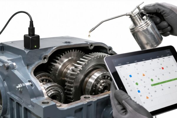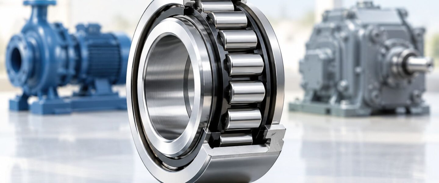
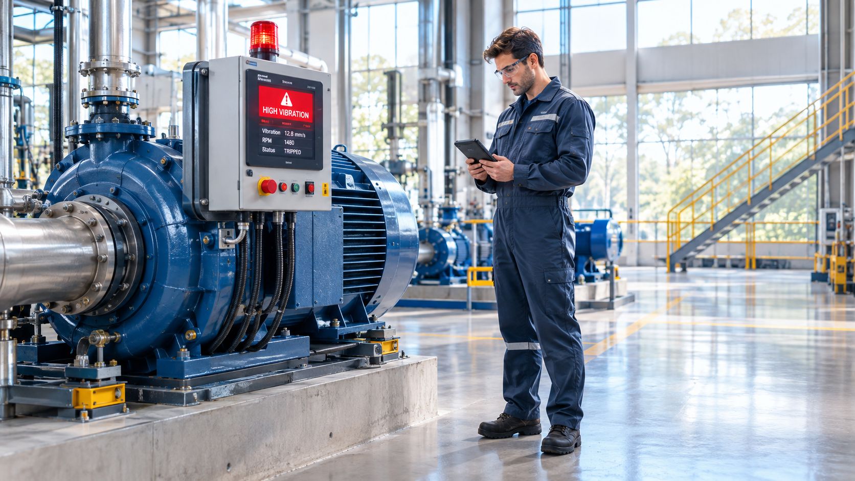
A critical process pump trips on high vibration during a production run. The maintenance team replaces the bearing, checks the coupling, and returns the pump to service. A short time later, the same alarm returns. The replacement bearing may be sound. The problem could be housing tilt, insufficient radial load, excess grease, axial rib overload, contamination, or electrical erosion from a driven motor.
Cylindrical roller bearings deserve this level of attention because their geometry offers exceptional radial load capacity, but gives the machine little tolerance for installation or operating errors. The rollers contact the raceway along a line instead of at a point, spreading load across a larger area. That makes the design useful in heavy-duty motors, gearboxes, pumps, compressors, rolling mills, and process equipment, while also making alignment control critical.
The practical question isn't whether the bearing can carry the catalog load. Reliability engineers and maintenance managers must determine whether the shaft and housing stay aligned, whether thermal growth has somewhere to go, whether the bearing remains sufficiently loaded at speed, and whether lubrication and electrical protection match the duty.
The sections that follow connect internal geometry with field symptoms. They show how to select a design for pumps, motors, gearboxes, and compressors, how to distinguish fatigue from skidding or contamination, and what to measure before removing a failed bearing. The central trade-off is straightforward: very high radial capacity comes with very tight alignment requirements.
Table of Contents
- Introduction Why Cylindrical Roller Bearings Make or Break Uptime
- How Cylindrical Roller Bearings Work and Key Design Variants
- How to Select Cylindrical Roller Bearings for Industrial Applications
- Common Failure Modes and Root Causes You Must Recognize
- Diagnostic Signatures and Condition Monitoring Techniques
- Best Practice Mounting Lubrication and Inspection Procedures
- Building Your Reliability Strategy and Next Steps
Introduction Why Cylindrical Roller Bearings Make or Break Uptime
A cylindrical roller bearing often sits inside equipment that operators notice only when it fails. In a process pump, it supports radial forces created by the shaft, impeller, coupling, and hydraulic system. In a gearbox, it carries gear mesh forces while the housing and shaft respond to torque, temperature, and load changes. In a motor, it may support belt or coupling forces while the electrical system introduces another source of stress.
The bearing's straight rollers create line contact with the raceway. Compared with point contact, this geometry distributes radial force across a larger contact area and gives the bearing high stiffness. That strength is valuable in a cement mill, rolling-mill drive, heavy gearbox, or process pump, where radial loading can remain severe for long operating periods.
The weakness appears when the shaft or housing tilts. Major bearing catalogs specify permissible misalignment of only about 3 to 4 minutes of arc for common single-row designs (SKF's general specifications for single-row cylindrical roller bearings). Even a small angular error can concentrate force at the roller ends, increasing noise, edge loading, and service-life loss.
The recurring plant-floor mistake
A failed bearing is often treated as an isolated component problem. The team checks the part number, orders a replacement, and assumes the next installation will restore reliability. That approach misses the machine-level causes that repeat across assets.
A pump bearing with raceway spalling may reflect misalignment. A gearbox bearing with smeared roller ends may have skidded because the radial load was too low or the lubricant was churning. A motor bearing with fluting-like electrical erosion may require a grounding and inverter-duty review, not another identical bearing.
Practical rule: A replacement bearing should close a diagnostic investigation, not end one.
The useful decision is therefore broader than “which bearing failed?” It is “what load path, motion, lubricant, temperature, or electrical condition damaged it?” Once that question is answered, the maintenance team can correct the cause and decide whether the existing bearing arrangement remains suitable.
How Cylindrical Roller Bearings Work and Key Design Variants
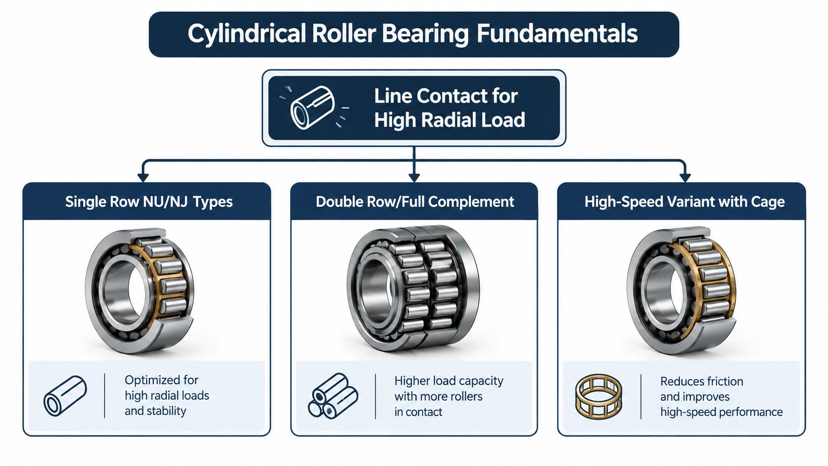
A cylindrical roller bearing can be understood by following the load path. The shaft turns the inner ring. The rollers sit between the inner and outer raceways, and the stationary housing receives the force through the outer ring. Because each roller touches the raceway along a line, radial force spreads over a broad contact zone instead of concentrating at a single point.
That geometry makes the bearing stiff and well suited to heavy radial service. A cage, where fitted, keeps the rollers separated and helps guide them. A full-complement design omits the cage and packs in more rollers, which can support heavy loads, while a caged design generally offers better roller separation for speed and lubricant control.
Rib arrangements determine axial behavior
The ribs, also called flanges, guide the rollers and determine how the bearing handles axial movement. A non-locating arrangement allows the shaft to move axially relative to the housing. A locating or semi-locating arrangement guides the shaft in a defined direction while managing thermal expansion elsewhere in the bearing set.
For example, a design with one rigid rib on the outer ring and two rigid ribs on the inner ring can guide the shaft axially in one direction while acting as a non-locating bearing in the opposite direction. This semi-locating behavior is useful in electric motors and gearboxes, where shaft and housing temperatures can rise differently (Schaeffler's explanation of single-row full-complement cylindrical roller bearings).
Clearance matches heat and speed
Internal clearance is the working space between the rollers and raceways before the bearing reaches operating temperature. As the shaft, rings, and housing expand, that clearance can shrink. Higher-clearance grades such as C3 and C4 help manage thermal expansion in hotter applications, but the grade must match the actual fit, temperature, speed, and load.
A bearing with too little operating clearance can run hot and develop excessive contact stress. A bearing with too much clearance can lose stiffness, alter load distribution, and increase vibration. Selection teams should review the manufacturer's clearance guidance rather than treating C3 or C4 as automatic upgrades. A useful companion reference for understanding bearing dimensions and fit decisions is this guide to bearing size 6202.
How to Select Cylindrical Roller Bearings for Industrial Applications
Selection begins with the machine, not the old bearing number. A pump may need high radial capacity but also tolerate shaft movement caused by temperature. A gearbox with spur gears may have mainly radial loading, while a helical gear arrangement can impose thrust that a free-floating design cannot carry. A high-speed motor may need a caged design, carefully controlled lubricant quantity, and operating clearance that remains stable after heat rise.
Misalignment is an early screening question. Cylindrical roller bearings tolerate very little angular error, so the team should examine shaft deflection, housing bore alignment, soft foot, coupling condition, and thermal movement. If the machine can exceed the catalog misalignment limit, the problem may require a different bearing arrangement or a correction to the shaft and housing geometry.
Application decision matrix
| Application Factor | What to Check | Preferred Design Choice |
|---|---|---|
| Radial load | Force perpendicular to the shaft, shock, stiffness, and available space | Caged, full-complement, or multi-row cylindrical design matched to the load |
| Speed | Running speed, acceleration, heat generation, cage behavior, and lubricant churning | Caged design with suitable clearance and lubrication control |
| Minimum load | Whether the rollers remain loaded at the lowest operating load and highest speed | Design and preload strategy that prevents skidding |
| Axial movement | Thermal expansion between shaft and housing | Non-locating or semi-locating arrangement with verified displacement capability |
| Misalignment | Shaft deflection, housing geometry, and operating tilt | Correct alignment first, or select a bearing arrangement that tolerates the condition |
| Temperature | Heat generation, fits, clearance, and lubricant viscosity at operating temperature | Appropriate clearance grade and lubricant strategy |
| Electrical environment | VFD operation, shaft voltage, grounding, and current paths | Insulated or electrically protected arrangement where engineering review requires it |
Match the designation to the load path
A free-floating design isn't suitable merely because its radial rating looks adequate. If a gearbox produces sustained thrust, the ribs may overheat or wear. If a motor must absorb thermal expansion, an overly locating arrangement can load the bearing set as temperatures rise.
Manufacturing teams preparing a purchase specification can use these application checks alongside the 2026 procurement specification steps. The specification should identify load direction, speed, temperature, clearance, lubrication, mounting conditions, electrical exposure, and acceptance measurements, not just the nominal bearing designation. A practical reference for coordinating selection with installation is this bearing selection and installation resource.
Common Failure Modes and Root Causes You Must Recognize
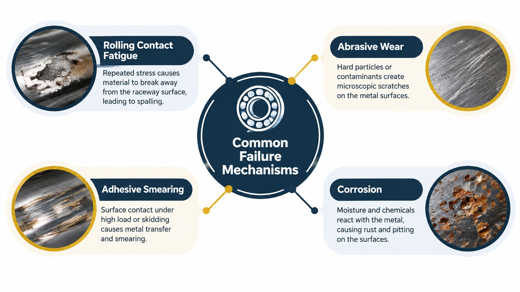
A failed bearing arrives from a gearbox or pump, and the raceway shows spalling. Replacing it may restore service briefly, yet the same damage can return if the underlying cause is misalignment, poor lubrication, contamination, excessive thrust, or an electrical current path. Start with a consistent vocabulary. ISO 15243:2017 groups rolling-bearing damage into rolling contact fatigue, wear, corrosion, electrical erosion, plastic deformation, and cracking or fracture (ISO 15243:2017). The classification separates the visible mechanism from the operating condition that produced it.
Rolling contact fatigue forms cracks beneath or at the surface. As those cracks grow, pieces of a raceway or roller can break away. Spalling in the loaded zone supports a fatigue diagnosis, but it does not identify the root cause. Check alignment, applied load, internal clearance, lubrication, and contamination before approving a replacement.
Read the surface before assigning blame
Abrasive wear produces scratches, dull tracks, or directional scoring. Hard particles may have entered through weak seals, dirty lubricant, poor storage, or inadequate contamination control. Adhesive wear and smearing show material transfer on the contact surfaces. Common contributors include roller skidding, insufficient load, poor lubrication, and lubricant churning at speed.
Corrosion appears as rust staining, pits, or a roughened raceway. Moisture ingress, condensation, washdown exposure, and long stationary periods can create it. Fretting around a ring seat points instead to small relative movement between the ring and shaft or housing. That finding shifts corrective action toward fits, clamping, or alignment.
Inspect ribs and cages, not only raceways
Rib damage deserves close attention in pumps and compressors carrying sustained thrust. The rib and roller-end interface combines contact stress with sliding, so rib geometry directly limits axial-load capability. For some ribbed designs, a continuous-load guideline is 1% of the radial load. Verify the specific design before accepting sustained axial force (JTEKT's bearing knowledge guidance on axial load).
Cage pockets may show wear, cracking, or polishing when rollers skew, lubrication is poor, or vibration is severe. Those marks can connect bearing geometry to the corrective action: correct alignment when contact is uneven, review lubricant quantity and viscosity when smearing dominates, and inspect grounding or insulation when electrical erosion appears. Use this guide to bearing failure causes to organize the investigation rather than treating every damaged bearing as a standalone part failure.
Diagnostic Signatures and Condition Monitoring Techniques
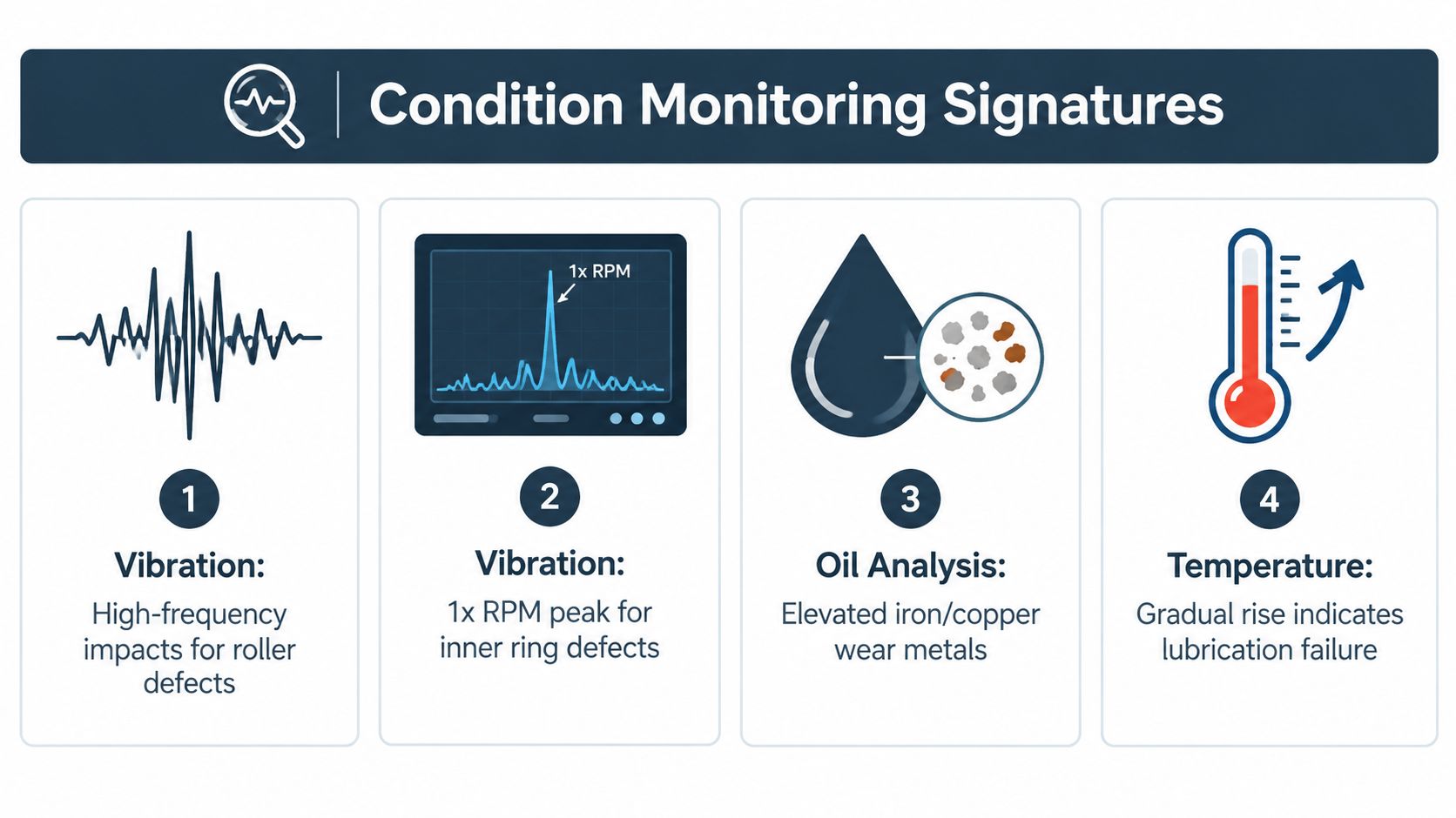
A pump begins running hotter, its vibration trend rises, and the bearing is blamed first. A reliable diagnosis compares several signals before anyone removes the bearing. Vibration shows the machine's dynamic response, temperature indicates heat generation, oil analysis reveals wear and contamination, while ultrasound and motor-current checks can expose friction or electrical effects hidden by an overall vibration value.
Record operating load, speed, temperature, lubrication condition, and recent process changes with every reading. A vibration alarm without this context can lead to an unnecessary replacement or leave the actual cause in service.
Use combined evidence
High-frequency vibration impacts can indicate developing roller or raceway damage. A repeating pattern tied to shaft rotation may identify a localized defect. Broadband energy can point to roughness, contamination, or lubrication distress. Interpretation depends on bearing geometry, speed, sensor position, and load, so a trend usually provides more value than one reading.
Geometry helps explain the pattern. A ribbed bearing carrying thrust may show a hot rib area alongside axial vibration, indicating sliding contact or thrust overload. Skidding can generate heat and smeared surfaces without the familiar spall pattern associated with rolling contact fatigue. Those findings direct the team toward load, alignment, or lubrication checks rather than automatic replacement.
Temperature adds another discriminator. A gradual rise after relubrication may indicate excess grease, churning, or an unsuitable lubricant. Oil analysis can reveal high wear metals, viscosity change, contamination, or degradation. A clean-looking bearing with abnormal iron may still have active surface distress, while visible debris and abrasive marks support a contamination pathway.
Check electrical causes on motor-driven assets
VFD-driven motors can expose rolling elements to electrical stress. Fluting patterns on raceways and washboard-like grey marks visible under magnification support an electrical-erosion investigation. Check shaft voltage, grounding, insulation, and current paths instead of relying only on mechanical readings.
Before pulling a bearing, record vibration spectra, temperature at both bearing locations, lubricant condition, shaft speed, load state, alignment readings, and relevant electrical measurements. Use this vibration analysis guide for bearing fault detection to connect signal patterns with physical inspection findings. The objective is a corrective action that matches the signature: restore alignment, correct lubrication, or improve electrical grounding when the evidence points there.
Best Practice Mounting Lubrication and Inspection Procedures
A bearing can be correctly selected and still fail during the first startup if installation changes its geometry or clearance. Before applying force, verify shaft and housing dimensions, surface condition, shoulder squareness, fits, and cleanliness. The force must pass through the ring being fitted. Pressing through the rollers can damage the rolling contacts before the machine runs.
Alignment is a centerline problem, not only a coupling problem. Bearing seats, housing bores, shaft shoulders, and the support frame must work together. Common single-row designs permit only about 3 to 4 minutes of arc of misalignment, so measure the geometry and keep it within the catalog limit.
A repeatable field procedure
Verify the fit. Measure shaft and housing seats, inspect shoulders, and compare the actual values with the bearing and machine specifications.
Control cleanliness. Keep the package sealed until installation. Clean tools and housings, and protect the bearing from dust, moisture, and handling damage.
Confirm operating clearance. Account for interference fits, temperature rise, shaft expansion, and housing growth. A C3 or C4 grade may suit a hot application, but only after reviewing its actual operating conditions.
Set the lubricant quantity. Too little lubricant can starve the contacts. Too much creates churning, raises temperature, and can encourage skidding at speed. Match viscosity and replenishment frequency to load, speed, and temperature rather than following a generic calendar rule.
Check minimum load. Lightly loaded rollers can slide instead of roll, particularly at high speed. Confirm that startup, low-load operation, and process changes keep the application within the manufacturer's minimum-load region.
Inspect after service. Examine raceways, roller ends, ribs, cage pockets, seals, and lubricant. Photograph and measure the parts before cleaning away evidence.
For lubricant selection in specialized motor or high-speed service, maintenance planners may consult System Engineering & Automation Kluber isoflex as part of a broader lubricant compatibility review. An auto-greasing system can improve delivery consistency, but it cannot correct the wrong grease, an overfilled housing, poor sealing, or an application that permits skidding.
Use the inspection evidence to choose the corrective action. Rib or roller-end distress can justify an axial-load, fit, or alignment review. Heat after greasing points toward quantity, churning, or viscosity. Fluting or electrical marks require grounding and insulation checks rather than automatic bearing replacement.
Inspection discipline: Keep the removed bearing, lubricant sample, seal condition, fit measurements, and operating data together throughout the failure investigation.
Building Your Reliability Strategy and Next Steps
A cylindrical roller bearing program works best when the plant treats the bearing as part of a rotating system. Critical pumps, compressors, gearboxes, motors, mill drives, and furnace fans need different monitoring depths based on consequence, duty, accessibility, and failure history.
Route-based vibration, temperature, ultrasound, and lubricant checks suit assets with stable operating conditions and accessible measurement points. Continuous monitoring is more appropriate when a failure develops quickly, the asset is difficult to access, or a trip carries serious production or safety consequences. The choice should follow criticality and failure behavior, not habit.
Build the strategy around failure mechanisms
An FMEA identifies how the bearing can fail, what causes each mode, and what controls can detect it. RCM then tests whether a predictive, preventive, run-to-failure, or design-change task is justified. A gearbox with repeated rib damage may need an axial-load review and alignment correction, while a VFD motor with electrical erosion may require grounding and inverter-duty controls.
Root cause analysis should begin when failures repeat, affect a critical asset, or show a mismatch between calculated life and operating life. A 5-Why analysis can trace a contaminated raceway back through seal damage, washdown practice, and maintenance handling. A fault tree can separate mechanical, lubrication, process, and electrical pathways when several conditions could produce the same alarm.
Sustain the correction
Food and beverage plants must control washdown moisture and contamination. Chemical processors need lubricant and seal compatibility. Power-generation assets often demand strong condition-monitoring coverage because access and consequences can make corrective work difficult. Mining, cement, metals, and steel equipment add shock, dust, high loads, and difficult installation conditions.
Spare-parts governance should preserve the correct bearing designation, clearance, cage, seals, and approved lubricant. The CMMS should record failure mode, operating hours, load state, measurements, photos, and corrective action rather than only the replacement date. Forge Reliability provides predictive maintenance, vibration analysis, oil analysis, thermography, ultrasound, motor-current analysis, and reliability consulting for rotating equipment, including pumps, compressors, motors, gearboxes, VFDs, rolling-mill bearings, crane gearbox bearings, and furnace fan bearings.
A bearing upgrade can be justified when improved geometry, lubrication access, cage design, or corrosion resistance addresses a verified failure mechanism. It shouldn't be used to hide poor alignment, weak sealing, uncontrolled contamination, inadequate minimum load, or an unresolved electrical path. The most durable improvement usually combines the right bearing with measured installation quality and a monitoring task that confirms the correction.
Forge Reliability can assess critical cylindrical roller bearing applications, review failure evidence, and build a practical monitoring and root-cause plan around vibration, oil, temperature, ultrasound, and electrical conditions. Visit Forge Reliability to request a free reliability assessment and identify the alignment, lubrication, load, or grounding actions most likely to reduce unplanned downtime.