The most common advice about an auto greasing system is also the most damaging: install the hardware, set a timer, and assume the lubrication problem is solved.
It isn't.
Plants regularly mount automatic lubricators on critical assets and still lose bearings, seals, and production time because the system was never engineered around the actual failure mode. A fan bearing in a chemical plant can fail with an auto-luber in place. A conveyor tail pulley can still run hot. A high-speed motor can suffer from too much grease, not too little. Automation only changes how grease is delivered. It doesn't prove that the right lubricant is reaching the right point, at the right volume, at the right interval, under the actual load and temperature conditions of the machine.
That distinction matters because the upside is real when the system is designed properly. Operators implementing auto greasing systems commonly report 40–70% savings in manual lubrication labor, 20–40% fewer lubrication-related stoppages, and 10–25% reductions in grease consumption, with reported payback periods typically falling between 12–24 months according to this automatic lubrication systems guide. But those results don't come from mounting pumps and routing tubing alone. They come from disciplined assessment, sizing, commissioning, and condition-based validation.
Table of Contents
- Why Most Auto Greasing Systems Fail to Deliver
- Conducting a Data-Driven Lubrication Needs Assessment
- Choosing the Right System Type for Your Application
- Calculating System Size and Lubricant Metering
- Commissioning and Integrating with Predictive Maintenance
- Diagnosing Common System and Lubrication Failures
- Your Long-Term Maintenance and Optimization Plan
Why Most Auto Greasing Systems Fail to Deliver
A failed bearing on an auto-lubed machine usually gets blamed on the bearing, the grease, or the installer. The actual issue is often simpler. The plant automated a task, not a reliability strategy.
An auto greasing system fails to deliver when the project begins with hardware selection instead of failure analysis. Maintenance installs a pump, routes lines to every visible fitting, sets a generic cycle, and moves on. Months later, the machine still shows rising temperature, vibration amplitude, or grease purge at the seals. The system is running. The asset still isn't healthy.
Automation doesn't eliminate lubrication risk
Automatic lubrication can remove inconsistency from manual greasing, but it can also lock in a bad practice if the delivery rate is wrong. A paper mill roll bearing with contamination exposure doesn't need the same approach as a clean, lightly loaded motor bearing in a packaging line. Treating both with the same timer logic creates predictable failure.
Practical rule: If the team can't explain which failure mode the auto greasing system is supposed to prevent, the design work isn't finished.
Common failure mechanisms tied to poor lubrication strategy include:
- Film starvation: Too little grease reaches the rolling elements, leaving metal-to-metal contact under load.
- Seal distress: Excess grease pressure pushes through seals, allowing contamination ingress later.
- Thermal loading: High-speed applications can churn grease and generate heat when volumes are excessive.
- Contamination retention: A system may keep feeding grease into a dirty cavity without improving cleanliness or film quality.
The gap between installation and proof
Most guidance in the field stops at mounting brackets, reservoir filling, and tubing layout. It rarely asks the question reliability teams need answered: did the system reduce the targeted failure mode?
That's the critical gap. The strongest auto greasing system programs treat installation as the midpoint, not the finish line. The work only counts when the team can verify that the bearing temperature stabilized, vibration signatures improved or remained controlled, and grease condition supports the intended service interval.
A mining conveyor is a good example. The mechanical installation may be straightforward. The reliability challenge is not. The system has to survive contamination, line damage, and variable duty while still delivering consistent grease volumes to head pulley, tail pulley, and take-up bearings. If the team never checks condition data after startup, it won't know whether the system improved bearing life or just changed who applies grease.
That's why the rest of the design process matters: assess the assets, choose the right architecture, size the metering correctly, then validate the result against machine health data.
Conducting a Data-Driven Lubrication Needs Assessment
A plant doesn't need an auto greasing system everywhere. It needs one where lubrication failure creates the most operational risk or where manual methods are too inconsistent to control.
A disciplined assessment prevents two expensive mistakes. The first is automating low-value assets while critical machines stay on weak manual routes. The second is buying a system before the team understands grease demand, access constraints, contamination risk, and consequence of failure.
Start with asset criticality and failure consequence
Start by ranking assets by production impact, safety exposure, repair complexity, and detectability of failure. In practice, the best early candidates are usually machines with multiple lubrication points, poor access, continuous duty, or severe contamination.
Consider exhaust fans in a chemical processing unit. These machines often run continuously, sit in difficult-to-access areas, and create immediate operating risk if a bearing fails. They're stronger candidates than lightly loaded utility assets that can be serviced easily during planned downtime.
A useful screening list includes:
- Criticality to throughput: Does failure stop production, reduce capacity, or create a process upset?
- Lubrication access: Does the technician need ladders, guards removed, or shutdown coordination to grease safely?
- Failure history: Has the asset shown repeated bearing, seal, or lubrication-related work orders?
- Operating severity: Does the machine run hot, wet, dirty, or continuously?
- Point count: Does the asset have enough lube points that manual consistency is difficult?
Build the lubrication baseline before choosing hardware
Once the candidate assets are identified, collect the baseline data that the business case depends on. That means current lubrication labor, grease usage, cleanup burden, disposal burden, stoppage history, and failure patterns. For many plants, that baseline is scattered across route sheets, work orders, storeroom records, and technician memory, so it takes effort to assemble.
For a food processing conveyor line, the assessment should document every bearing point, current relubrication interval, grease type, average time per route, access method, and whether the machine must be stopped to grease it. It should also capture what “bad lubrication” looks like on that line: hot bearings, grease sling, product contamination concerns, frequent seal replacement, or recurring bearing changeouts.
Teams that want a structured framework for that baseline can use an equipment condition assessment for lubrication systems to connect lubrication practices to asset risk rather than treating greasing as a standalone task.
A weak baseline creates a weak design. If the plant doesn't know current grease demand or current lubrication-related failure patterns, it can't set the new system correctly.
Assessment questions that change the design
Some of the most important questions are qualitative, not numeric:
- Is the asset failing from contamination ingress, inadequate replenishment, or over-greasing damage?
- Does the bearing housing purge old grease effectively, or does it trap excess material?
- Does load change during operation, such as variable-speed conveyors or seasonal process fans?
- Are multiple grease types already being used in the area, creating compatibility risk during conversion?
The output of this assessment should be more than a project justification. It should define reliability targets. For example, the objective on a bank of process fans may be to stabilize bearing temperatures, eliminate inaccessible manual grease routes, reduce nuisance stoppages tied to lubrication, and improve consistency across all bearings in that service.
That's what separates a lubrication project from a reliability project. The hardware comes later.
Choosing the Right System Type for Your Application
System architecture drives whether the auto greasing system will be easy to troubleshoot, scalable across the asset, and appropriate for the grease and duty cycle involved. A poor match creates chronic blocked lines, weak fault visibility, or delivery inconsistency at the farthest point.
Automated grease systems reduce unplanned downtime by preventing inconsistent lubrication and over-lubrication, which are identified as two of the top five causes of equipment failure in manual maintenance programs in this overview of automatic grease systems.
What each architecture does well
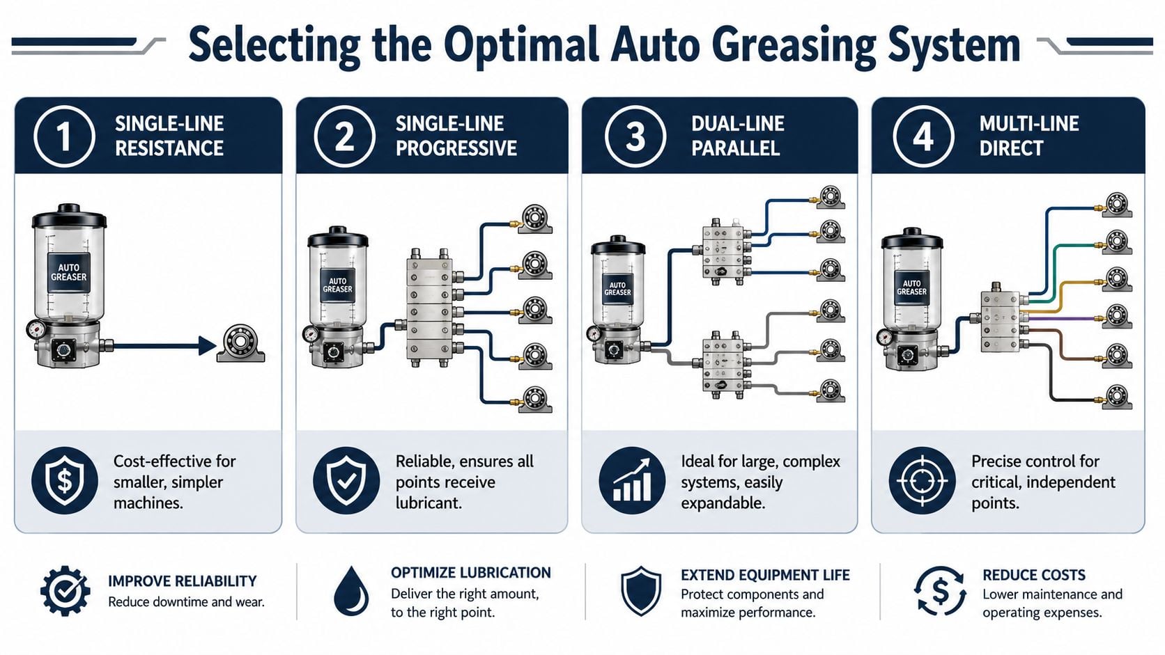
The most common architectures seen in industrial service are single-line resistance, single-line progressive, dual-line parallel, and multi-line direct systems. Each solves a different problem.
Single-line resistance systems fit smaller, simpler machines with modest point counts and stable operating conditions. They can be cost-effective, but they're less forgiving when point demand varies or when fault visibility is limited.
Single-line progressive systems work well when the team wants clear sequencing and better confirmation that all points are receiving lubricant. These are often a strong fit for compact, critical machinery where a missed outlet matters and troubleshooting needs to be direct.
Dual-line parallel systems are stronger on large equipment with long line runs and many lubrication points. Steel, mining, and other large industrial environments often benefit from their expandability and line-length capability.
Multi-line direct systems are useful when each point needs more independent control. They make sense on assets where the points differ substantially in demand or where independent outlet management simplifies reliability control.
For a machine-specific design review, a plant can map the selected architecture against asset constraints using this lubrication systems equipment overview.
Auto Greasing System Type Comparison
| System Type | Operating Principle | Best For | Pressure | Limitations |
|---|---|---|---|---|
| Single-Line Resistance | One supply line feeds metered restrictions to points | Smaller, simpler machines | Moderate | Limited fault visibility, less flexible for variable point demand |
| Single-Line Progressive | Divider valve sequences lubricant through outlets in order | Compact critical assets needing delivery assurance | Moderate to high | A blockage can affect downstream delivery |
| Dual-Line Parallel | Two main lines alternate pressurization across distribution blocks | Large, complex systems with long runs | High | More complex infrastructure and commissioning |
| Multi-Line Direct | Pump feeds multiple independent outlets directly | Critical points needing precise independent control | Moderate to high | Higher component count at the pump and less efficient for very large distributed layouts |
Matching the system to the asset
A steel mill roll table and a high-speed packaging machine shouldn't use the same selection logic.
For the mill, line length, harsh environment, and scalability typically dominate. For the packaging machine, point verification, compactness, and sensitivity to over-lubrication matter more. On mobile or exposed equipment, line damage resistance and routing simplicity may outweigh every other criterion.
The right system type is the one that makes failure obvious, not hidden.
That's why reliability teams should test architecture choices against three practical questions:
- Can maintenance isolate a fault quickly?
- Can the system tolerate the grease and environment without chronic blockage?
- Can the team verify delivery at each critical point without guesswork?
If the answer to any of those is no, the chosen architecture is probably wrong, even if the purchase price looks attractive.
Calculating System Size and Lubricant Metering
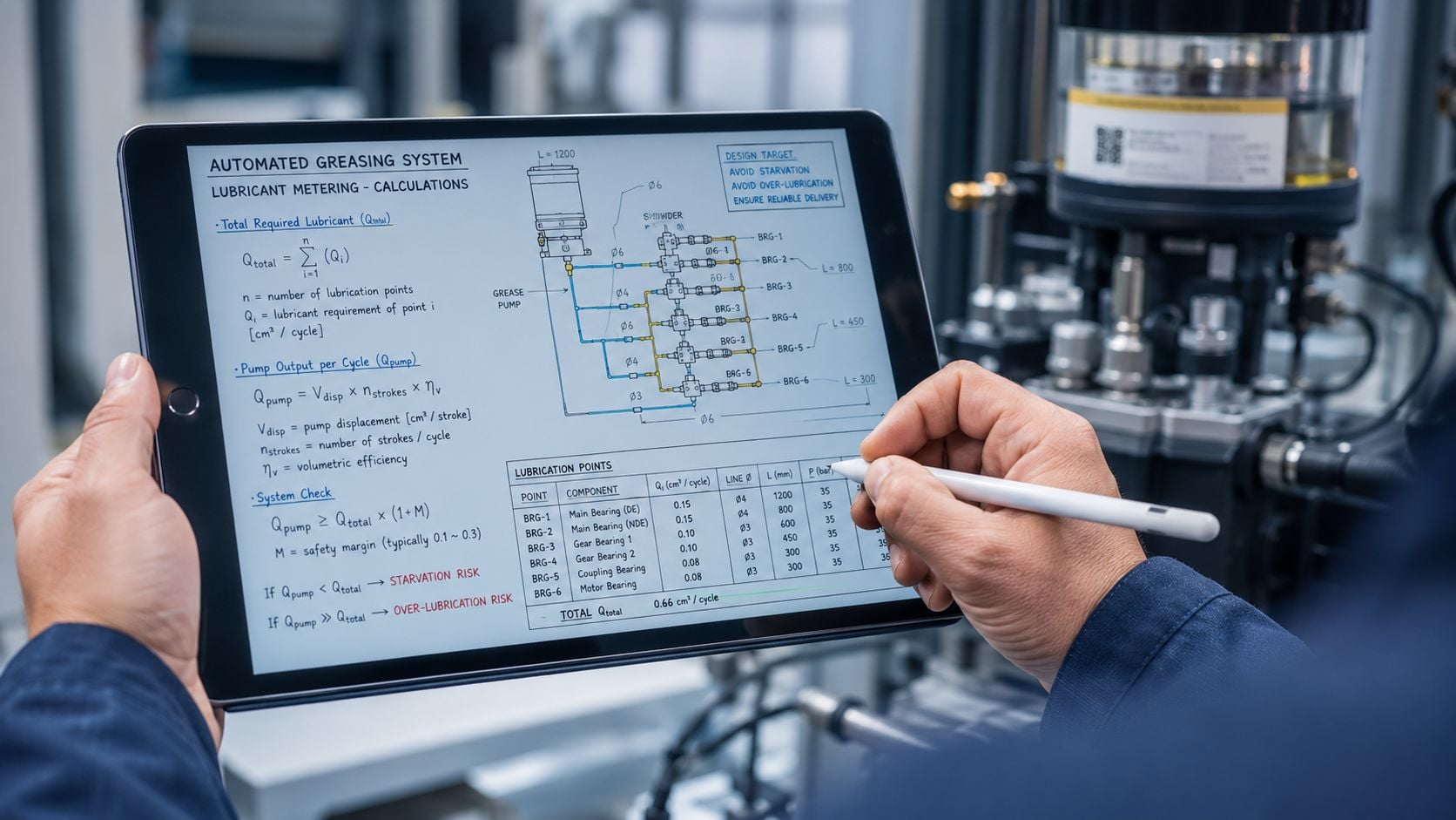
Sizing is where many auto greasing system projects go off track. The system either starves bearings because the metering is too conservative, or it floods housings because someone copied a manual grease route directly into an automated cycle without adjusting for continuous delivery.
The inputs that matter
The required metering rate depends on the bearing type, speed, load, duty cycle, housing design, grease properties, ambient conditions, and contamination exposure. Those variables determine how much grease the point needs and how often it should be replenished.
Grease selection also matters to system design, not just bearing protection. In automatic lubrication systems, five primary failure modes dominate industrial service: oxidation deterioration, oil separation, hardening and coking, foreign contamination, and failure due to incompatible grease mixing. For equipment operating continuously or at high temperatures, grease replacement intervals need to be shortened, and synthetic oils with antioxidant additives such as PAO or ester-based formulations are prioritized to extend lubricant life, as outlined in this industrial grease failure mode review.
That means sizing work should include more than “how much grease per cycle.” It should also address:
- Grease compatibility: Thickener incompatibility can create hardening or separation during conversion.
- Base oil viscosity: The lubricant has to support the bearing's speed and load regime.
- NLGI grade and pumpability: The grease must move through the line lengths and ambient conditions involved.
- Housing purge path: Excess grease needs a controlled exit path, especially in motor and fan bearings.
A practical sizing workflow for a process fan
Take a large induced-draft fan in a process plant. It runs continuously, has two pillow block bearings, and sits in a hot, dusty area. The engineering sequence should follow the machine, not the catalog.
- Define the point demand. Determine the relubrication requirement for each bearing based on operating severity and housing design.
- Convert manual interval logic into automated interval logic. Instead of one larger manual shot, divide the requirement into smaller, more frequent doses.
- Select metering devices to match each point. If the drive-end and non-drive-end bearings don't carry the same load or run at the same temperature, they shouldn't automatically get identical output.
- Check pump and reservoir capacity. The pump must deliver enough volume and pressure across all active points, while the reservoir must support the refill interval the plant can realistically maintain.
- Review line diameter and routing. Long runs, low temperatures, and stiffer greases increase resistance. Poor line sizing produces delayed delivery and false troubleshooting signals.
A well-sized design also avoids one of the most common hidden errors in the field: ignoring startup and purge volume. If the line network contains significant internal volume, the first cycles may only fill lines and divider blocks rather than lubricate bearings. Commissioning settings must account for that.
Small doses at the correct interval usually outperform large manual shots because they maintain the film with less thermal disturbance and less seal stress.
For critical fans, motors, and gearboxes, the final check should ask a simple question: if this metering rate is wrong, what symptom will appear first? On some assets it will be rising temperature. On others it will be grease purge, increased vibration, or increased running torque. That expected symptom should be defined before startup, not after failure.
Commissioning and Integrating with Predictive Maintenance
Most auto greasing system projects are commissioned mechanically, not diagnostically. The pump runs, the timer is active, grease reaches the line ends, and the job gets signed off. That isn't enough for critical rotating equipment.
Data shows 30% of unplanned downtime in rotating assets stems from inadequate lubrication, yet many guides still don't integrate vibration analysis or oil analysis to confirm that the auto-greaser is creating the correct lubricant film under dynamic load conditions, as noted in this discussion of lubrication validation gaps.
Commissioning that verifies delivery
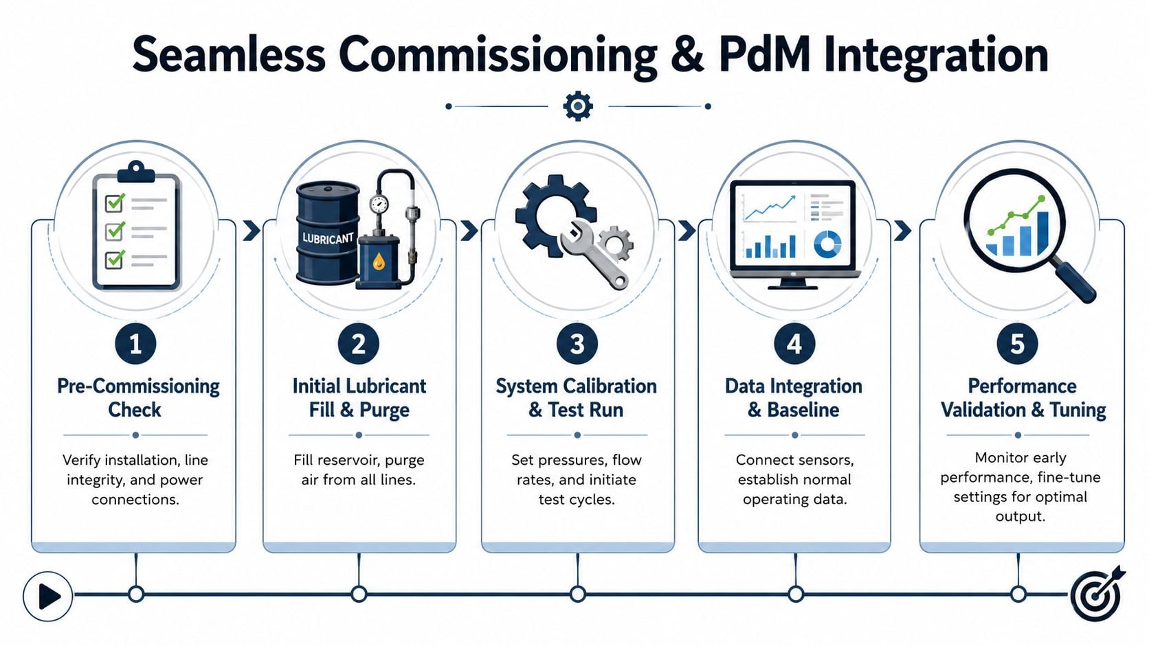
A proper commissioning sequence proves three things: the system is mechanically sound, lubricant is reaching every intended point, and the initial settings align with machine response.
For a bank of conveyor head pulley bearings in a bulk handling plant, that means more than checking for leaks. It means confirming line integrity, purging trapped air, verifying divider or injector operation, observing actual discharge at the bearing entry point where possible, and documenting baseline operating condition after startup.
A reliable commissioning checklist includes:
- Pre-start verification: Confirm line routing, fitting tightness, power or control connections, and purge paths at each bearing housing.
- Air removal: Fill the reservoir correctly and purge the network so compressed air doesn't create delayed or false delivery.
- Metering confirmation: Validate injector or divider output against the intended setting instead of assuming nameplate values are correct in service.
- Test cycle observation: Run enough cycles to confirm delivery reaches all points, especially the most remote ones.
- Control logic review: Verify alarms, low-level indications, and fault outputs are visible in the maintenance workflow.
Condition monitoring teams can formalize that process through a condition monitoring approach for lubrication systems so that lubrication events and machine health data are reviewed together instead of in separate silos.
Using PdM data to validate lubrication efficacy
At this stage, most projects either become reliable or become expensive.
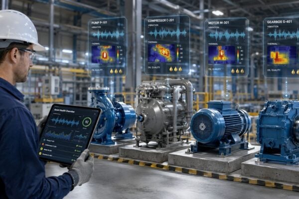
Baseline vibration and thermography should be taken immediately after stable operation is established. Baseline means the machine is operating normally, the system has been purged and set, and the team has documented the exact lubrication configuration in place. Later changes in temperature or vibration then have context.
A useful validation model for a motor-driven pump train or fan train includes:
- Vibration analysis: Track bearing condition indicators, high-frequency energy, and overall trend stability after the auto greasing system is enabled.
- Thermography: Watch for gradual temperature increase that may point to over-lubrication, blocked delivery, or grease churning.
- CMMS event logging: Record lubricant refills, setting changes, blockages, and repairs in a way that can be trended against condition data.
- Trend interpretation: Review the combined signals instead of chasing one symptom in isolation.
Teams that want stronger trending logic for lubrication-related signals can use methods similar to PlotStudio AI analytics for time series to think through pattern detection in temperature, vibration, and event data across long operating windows.
A commissioned system isn't proven when grease appears at the outlet. It's proven when asset health stays controlled after the system enters normal duty.
That's the step most installation guides miss. The point isn't to automate grease application. The point is to confirm that the machine's failure behavior has changed.
Diagnosing Common System and Lubrication Failures
When an auto greasing system underperforms, maintenance teams often start with the obvious causes: empty reservoir, failed pump, broken line, blown fuse. Those are real faults, but they aren't the most expensive ones. The harder failures are the ones where the system appears healthy while the asset isn't.
System faults versus lubrication faults
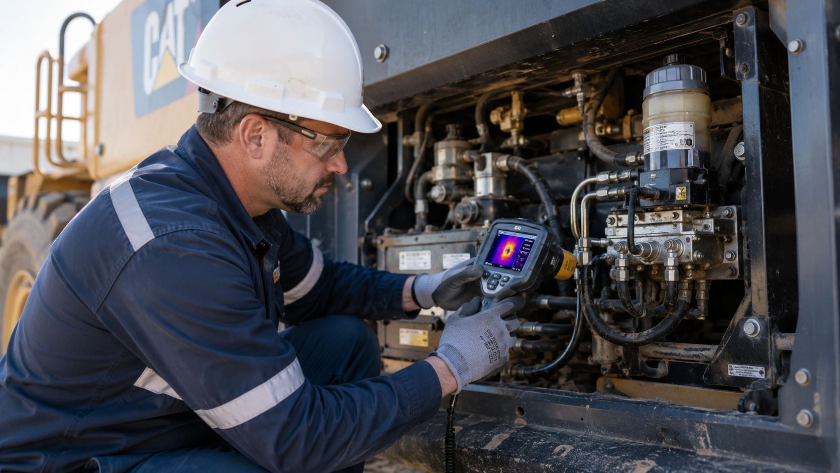
Start by separating delivery problems from lubricant performance problems.
A delivery problem means grease isn't reaching the point as intended. Causes include blocked lines, stuck divider sections, failed injectors, trapped air, or damaged fittings. These faults are often diagnosed through pressure behavior, controlled isolation, direct outlet checks, and physical inspection of line condition.
A lubrication performance problem means grease is reaching the point, but the asset still isn't protected. That may come from wrong grease selection, incompatible residual grease, excessive volume, poor purge path, contamination ingress, or thermal degradation at the bearing.
For a VFD-controlled motor driving a process pump, both categories can look similar at first. Bearing temperature rises. Vibration changes. Operators hear more noise. The distinction comes from the evidence. If pressure and outlet checks show delivery is occurring, the team should shift quickly toward grease behavior, bearing housing design, and actual operating speed.
Teams dealing with repeated failures should document the logic through a formal root cause analysis process for lubrication systems so that they don't keep replacing components without resolving the mechanism behind the failure.
Recognizing grease degradation and over-lubrication
Over-lubrication remains one of the most overlooked causes of damage in automatic systems, especially on high-speed assets. Emerging 2025–2026 data indicates that 22% of auto-greasing system failures in high-speed applications stem from over-lubrication, not under-lubrication, according to this troubleshooting review of automatic lubrication issues. Because that figure is tied to emerging 2025–2026 data, it should be treated as a directional finding rather than a timeless rule for every plant.
Common signs of over-lubrication include:
- Temperature rise after relubrication: Often linked to churning losses in high-speed bearings or gear-driven components.
- Grease purge at seals: Indicates the cavity may be overfilled or the relief path is poor.
- Increased energy draw or sluggish running: A sign that excess grease is creating drag.
- Premature seal wear: Excess pressure can distort or damage seal lips.
Grease condition itself also tells a story. Darkened, hardened, separated, or contaminated grease points to the wrong interval, wrong formulation, incompatible mixing, or environmental control problems. If the plant sees coked deposits in hot zones, soft oil-separated material in lines, or abrasive contamination in purge material, the issue is bigger than injector adjustment.
When a high-speed bearing runs hotter after an auto greasing system is installed, the first question shouldn't be “why isn't it getting enough grease?” It should be “did the system start feeding too much?”
Thermography, vibration trends, inspection of purge condition, and pressure observations together will usually identify the fault path faster than replacing hardware one piece at a time.
Your Long-Term Maintenance and Optimization Plan
An auto greasing system is not maintenance-free. It's a critical subsystem with its own failure modes, inspection tasks, contamination risks, and calibration needs. Plants that treat it like permanent set-and-forget hardware eventually lose both the system and the asset it's supposed to protect.
Treat the lubrication system like a critical asset
A long-term plan should sit in the CMMS the same way any other preventive strategy does. The system needs routine reservoir checks, filter and breather attention where applicable, line inspection, fitting inspection, metering device function checks, alarm verification, and refill discipline that prevents contamination during handling.
A practical ongoing task set includes:
- Reservoir management: Check fill condition, cleanliness, and signs of separated or aged grease before topping up.
- Line condition review: Inspect tubing and hose routing for abrasion, crushing, vibration damage, or heat exposure.
- Metering verification: Function-test divider sections or injectors when machine symptoms suggest unequal delivery.
- Control integrity: Confirm low-level, fault, and cycle indicators are still visible to operations or maintenance.
- Lubricant governance: Prevent grease substitution errors and unmanaged mixing during refill or conversion work.
The same mindset used in fleet programs also helps here. A structured inspection cadence from a resource like this proactive fleet vehicle care guide is useful as a parallel example of why repeatable checks beat reactive fixes, even though the equipment class is different.
Safe fault isolation and continuous optimization
When faults do occur on high-pressure systems, troubleshooting has to be deliberate. Critical diagnostic protocols include detailed system documentation review, complete pressure relief before disconnection, lockout/tagout procedures, and progressive isolation testing to pinpoint failure locations, as detailed in this grease block troubleshooting guide.
That sequence matters because grease injection injuries are serious, and because random disassembly often creates more uncertainty than it removes.
A safe progressive isolation approach usually follows this order:
- Review current drawings and maintenance history so the team knows what was changed and where.
- Relieve system pressure completely before any disconnection.
- Apply lockout/tagout to remove startup risk.
- Verify main supply pressure behavior first.
- Isolate downstream sections step by step until the restriction or failed component is found.
Plants should also use operating data to tune the program over time. Static OEM intervals are only a starting point. If temperature remains flat, vibration stays controlled, and purge condition is clean, the team may confirm that the interval is appropriate. If the asset shows rising heat after events or chronic purge at seals, settings need adjustment.
A planning framework built around maintenance planning for lubrication systems helps connect those inspections, work orders, and condition findings back into a closed-loop reliability program.
The strongest long-term plans share three traits:
- They preserve system health. The auto greasing system itself gets inspected, tested, and maintained.
- They protect the lubricant. Refill, storage, compatibility, and contamination control are managed deliberately.
- They refine settings with evidence. Interval and metering changes are driven by asset condition, not habit.
An auto greasing system delivers its best value when it becomes part of reliability engineering, not just a substitute for a grease gun.
A well-designed auto greasing system should do more than automate lubrication. It should reduce failure risk, support predictive maintenance, and extend asset life with measurable control. If that isn't happening, the design, commissioning, or validation process needs work. Forge Reliability can help evaluate lubrication strategy, condition data, and failure modes through a free reliability assessment.