A production line motor rarely fails at a convenient time. The call usually comes during a shift change, with operations asking why a conveyor, pump, fan, or compressor is down and how fast it can return to service. In many plants, the motor already gave warning. The warning was in the insulation data, but the reading was treated as a one-time checkbox instead of a condition signal.
That's why motor insulation resistance testing matters. For reliability engineers, maintenance managers, and plant operations leaders, it isn't just an electrical test. It's one of the clearest ways to see moisture ingress, contamination, insulation aging, and risk before a winding fault forces an outage. Its true value comes when the test is performed correctly, interpreted with context, and used with the right companion diagnostics, especially on VFD-driven motors where a “good” megger reading can still hide a real problem.
Table of Contents
- Beyond the Pass-Fail Why IR Testing Matters
- Preparing for a Safe and Accurate Test
- Performing the Insulation Resistance Test Procedure
- Interpreting Results and Acceptance Criteria
- Diagnosing Common Failures and Planning Corrections
- Integrating IR Testing into Your PdM Program
Beyond the Pass-Fail Why IR Testing Matters
A maintenance team in a packaging plant pulls a failed motor from a critical conveyor. The replacement is available, but production has already lost hours. After the rush, the usual question shows up. Was this motor failure sudden, or was it predictable?
In many cases, insulation deterioration wasn't sudden at all. The problem is that teams often treat motor insulation resistance testing as a pass-fail exercise. A quick reading above the minimum gets the motor released, and no one asks what the trend is, whether the insulation is drying out properly during the test, or whether the asset is exposed to conditions that accelerate winding damage.
A single reading is only a snapshot
A megohm value by itself can tell a technician whether insulation to ground looks acceptable at that moment. It can also point quickly toward moisture, dirt, oil film, or age-related breakdown. But one reading can mislead when teams skip context.
A better approach is to treat each test as a data point in a history. That's where the test starts helping prevent downtime instead of merely documenting it after the fact. A practical framework for building that broader motor health picture is to combine insulation work with a structured program of electric motor maintenance, testing, and monitoring.
Practical rule: If a motor is critical enough to stop production, it's critical enough to trend. A pass today doesn't answer whether the insulation is stable, improving, or declining.
Electrical safety teams already understand this mindset in other contexts. Anyone who's worked around facility electrical compliance will recognize a similar principle in what is PAT testing. The test itself matters, but the main value comes from disciplined inspection, documentation, and action based on results.
Why operations leaders should care
For operations leaders, the issue isn't only technical. It's economic and scheduling-related. A motor failure rarely stays confined to the motor. It interrupts throughput, strains labor, and often forces rushed decisions about spare assets and repair scope.
Motor insulation resistance testing gives maintenance teams an early look at whether an insulation system is staying dry, clean, and intact. That matters in food plants with washdowns, in chemical units with vapor exposure, and in paper mills where humidity changes constantly. It also matters because a low reading is often a symptom of something physically correctable, not just a reason to condemn the motor.
The key lesson for new reliability engineers is simple. The megger doesn't just answer “can this motor run right now?” It helps answer “what is happening inside the insulation system, and what should be done before the next forced outage?”
Preparing for a Safe and Accurate Test
The test starts before the leads come out. Most bad insulation readings are not caused by the meter. They're caused by poor preparation, residual charge, dirty terminals, wet test conditions, or a motor that was never properly isolated.
In a food and beverage facility, that problem shows up constantly on washdown-duty motors. A motor can be electrically healthy and still produce misleading data if the terminal box is damp, the winding hasn't discharged, or the surface contamination creates a leakage path that distorts the result. The preparation step is where safety and data quality are either protected or lost.
Non-negotiable setup steps
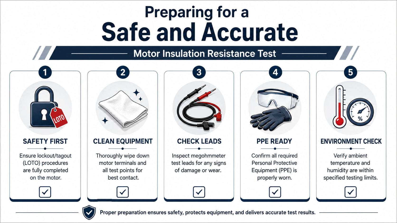
Before performing motor insulation resistance testing, the team should work through these checks in order:
Lock out and verify isolation. The motor must be de-energized, disconnected as required by site procedure, and protected by full lockout/tagout. This is not a paperwork step. It prevents exposure to stored or induced energy and keeps the test from being performed on a live circuit.
Discharge the winding. Windings hold capacitive charge. If that charge isn't discharged, the reading can drift for the wrong reason, and the test instrument can be stressed.
Clean the connection points. Wipe terminals, lead ends, and exposed insulating surfaces. Surface contamination can create leakage paths that make a motor look worse than it is, or hide where contamination is concentrated.
Inspect the test leads. Damaged leads create unstable readings and unsafe conditions. Good motor testing discipline starts with lead condition, not just meter selection.
Check the environment. Temperature and humidity matter. If a team ignores ambient conditions, the result may not be useful for comparison with prior tests.
PPE and electrical safety discipline
Technicians should also confirm that required PPE is in place before touching the motor or opening any enclosure. Arc flash boundaries, shock hazards, and local procedures still apply even when the motor is out of service. Teams that need a practical refresher on electrical safety clothing and hazard context can review Refinery Work Wear Canada's insights as a general reference.
Stored energy is one of the easiest ways to get false confidence during testing. A motor that is “off” is not automatically discharged, isolated, or safe to touch.
Accuracy starts with motor condition
A recently loaded motor should not be tested immediately if the goal is trending insulation condition accurately. Heat changes resistance behavior. Dirt and condensation do the same. A motor that has just come out of service after a hot run in a bottling area may need time, cleaning, and drying before the reading means anything.
This is one reason thermal data is useful before electrical testing. Surface temperature patterns and cooling behavior often help identify whether the motor has abnormal heating or environmental exposure. That broader context matters, particularly for induction motors, and it fits naturally alongside thermographic inspection for induction motors.
For a washdown-duty motor on a filling line, preparation should answer three questions before the first test voltage is applied. Is the motor isolated? Is the winding discharged? Is the test environment clean and stable enough to trust the result? If any answer is no, the team isn't ready to test.
Performing the Insulation Resistance Test Procedure
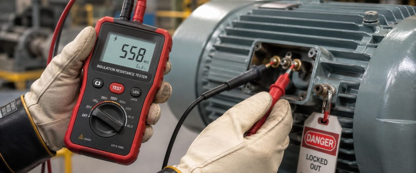
A megohmmeter is the instrument used for insulation resistance testing. It applies DC test voltage and measures resistance in the insulation system, usually between the winding and ground. The purpose isn't to see whether the winding carries load current. It's to determine whether insulation is preventing unwanted leakage to ground.
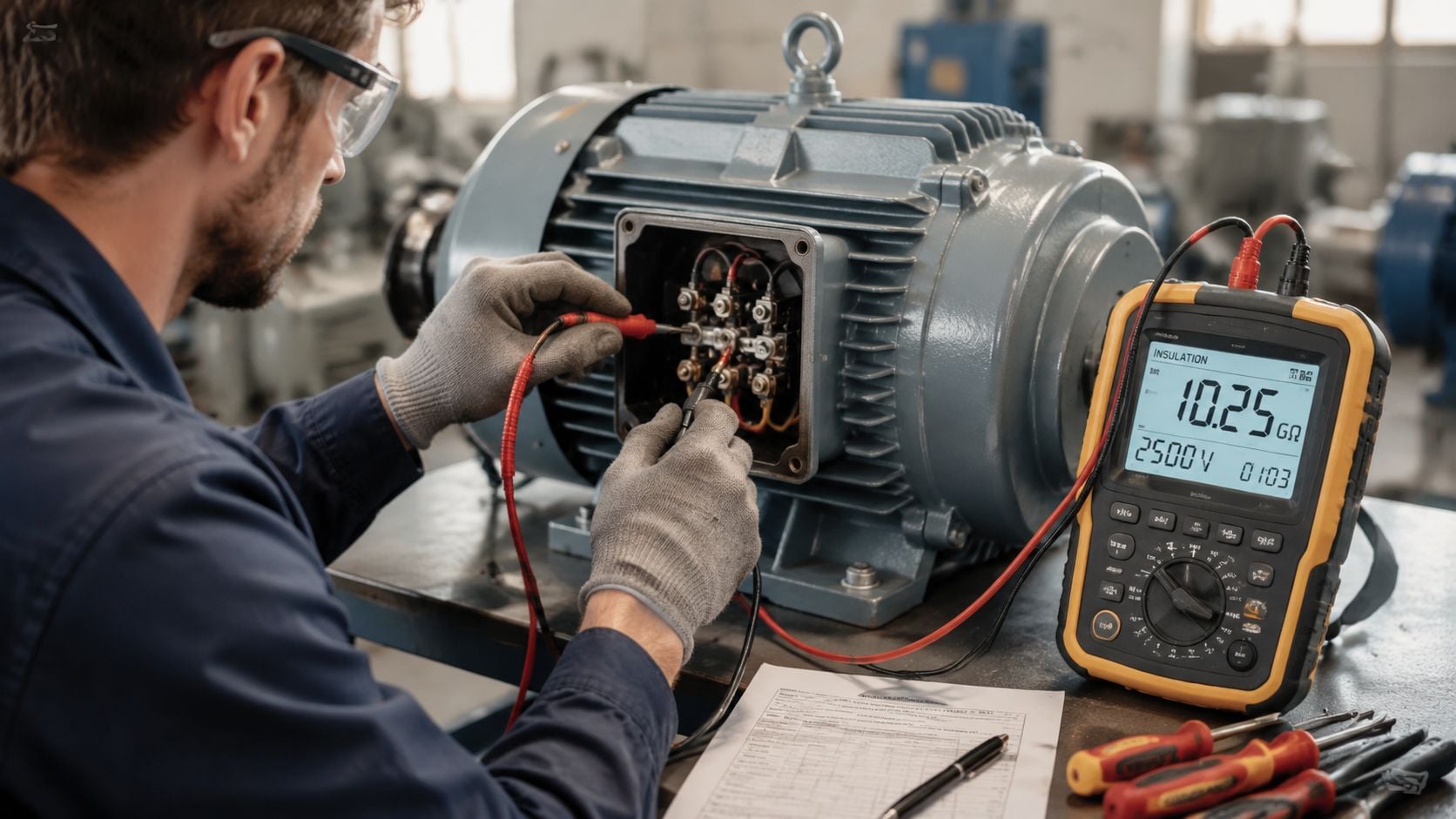
For a grounded insulation test on a motor, lead placement matters. The standard time-resistance method described in this motor insulation resistance procedure reference requires discharging the winding first, allowing the motor to cool to room temperature, typically 1–8 hours for a fully loaded unit, then connecting the negative megohmmeter lead to all winding leads and the positive lead to the motor frame (ground). The same method notes that 500 VDC is commonly used for 460V motors, with the test held for exactly 60 seconds to record the initial reading and continued to 10 minutes to calculate Polarization Index (PI) as the ratio of IR at 10 minutes divided by IR at 1 minute.
Step-by-step field procedure
A practical field sequence looks like this:
- Confirm the motor has cooled appropriately. Hot windings change resistance characteristics. If the unit was heavily loaded before shutdown, testing too early can distort the baseline.
- Isolate the circuit completely. The motor must be separated from the supply and any connected equipment paths that could interfere with the reading.
- Discharge before connecting the tester. This protects both the instrument and the technician.
- Connect for a ground-wall test. Negative lead to the winding leads. Positive lead to the frame.
- Apply the selected DC test voltage. For many low-voltage plant motors, the common field choice is the one already noted above for 460V equipment.
- Record the 1-minute value. This is the first critical time marker.
- Continue the test to 10 minutes. Record the 10-minute reading for PI.
- Discharge again after testing. The winding can retain charge after the test is complete.
Why timing matters
A quick spot reading is useful, but it doesn't tell the whole story. Time-resistance testing adds diagnostic value because insulation behavior changes during voltage application. As the winding absorbs charge and any moisture influence starts to separate from the underlying insulation response, the resistance trend becomes more meaningful.
That's why PI is a stronger indicator than a single instant reading. A dirty or damp winding can still produce a number that looks superficially acceptable at one moment. Watching the reading develop over time tells the team whether the insulation system is behaving like a dry, clean system or a compromised one.
The most common procedural mistake is rushing the test. If the team only wants a quick number, they'll get a quick answer. They won't necessarily get the right one.
Example from a chemical plant compressor motor
Consider a large compressor motor in a chemical processing area. The motor may sit near vapor sources, temperature swings, and contamination that doesn't show up during a routine visual inspection. If the team takes a fast reading right after shutdown, without cooling, discharge, or proper lead placement, the result may look inconsistent and trigger the wrong action.
A disciplined test procedure avoids that. It distinguishes between a measurement problem and an insulation problem. That difference matters because the corrective action could range from simple cleaning and drying to immediate removal from service. A poor method turns that decision into guesswork. A correct method turns it into engineering.
Interpreting Results and Acceptance Criteria
The reading itself isn't the decision. The decision comes from understanding what the reading means physically, how it compares with acceptance criteria, and whether the result is reliable enough to trend.
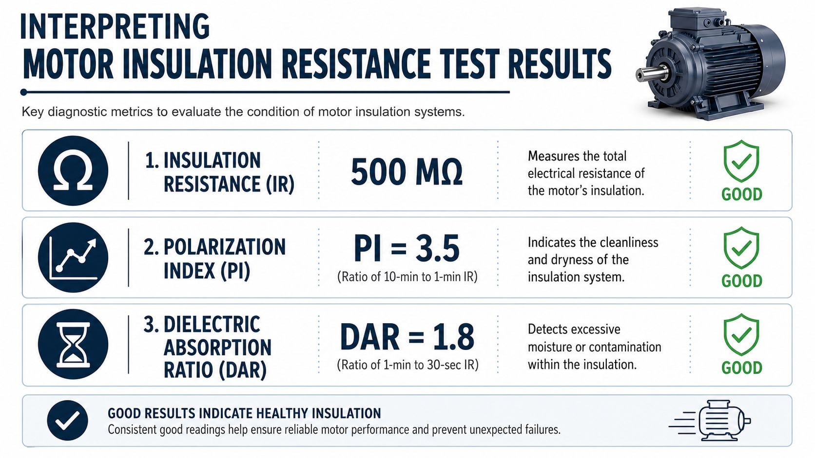
For reliability engineers and maintenance managers, three terms matter most during motor insulation resistance testing: IR, PI, and DAR. IR is insulation resistance. PI is Polarization Index. DAR is Dielectric Absorption Ratio. Each gives a different view of the insulation system, and each becomes more useful when interpreted with operating context.
What the numbers actually describe
IR is the total resistance of the insulation system to leakage current. A low value often points toward moisture, contamination, or degraded insulation to ground.
PI compares the 10-minute reading to the 1-minute reading. According to IEEE 43-2013 guidance summarized here, the foundational rule for minimum insulation resistance is the “one-megohm per kilovolt plus one megohm” formula. That same reference states that PI greater than 2.0 indicates good insulation condition, while PI less than 1.0 is dangerous and requires immediate investigation per NETA/ANSI maintenance standards.
DAR is the ratio of the 1-minute reading to the 30-second reading. It is commonly used when shorter test durations are needed, and it helps indicate whether contamination or moisture is affecting absorption behavior.
Acceptance table for PI and DAR
| Value Range | Insulation Condition | Recommended Action |
|---|---|---|
| PI below 1.0 | Dangerous | Remove from service decision-making path until investigated. Look for moisture, contamination, or serious insulation breakdown. |
| PI 1.0 to 1.5 | Caution | Follow up immediately. Compare with prior data, inspect for contamination, and verify temperature correction before release. |
| PI 2.0 to 4.0 | Good | Acceptable insulation condition. Continue trending and maintain routine follow-up. |
| PI above 4.0 | Excellent | Strong insulation response. Keep baseline and continue normal condition monitoring. |
| DAR showing a strong rising absorption pattern | Generally favorable | Use as a supporting metric, especially on shorter-duration testing. |
| DAR showing weak absorption behavior | Possible moisture or contamination concern | Inspect the winding condition and confirm whether the surface and environment affected the test. |
Decision point: The number is only actionable when the team knows whether it reflects the winding, the temperature, the surface condition, or the test setup.
A useful companion diagnostic for electrical faults that insulation resistance alone can't expose is motor current signature analysis for fault detection. That becomes especially important when the motor runs on a drive, as covered later.
Why temperature correction changes decisions
Temperature correction is not optional if the team wants credible trending. The procedure reference used earlier states that the measured IR value should be corrected to the standard 40°C reference temperature using IEEE 43 or ANSI correction factors, and it adds a practical rule of thumb that the temperature-corrected IR should be at least four times the minimum level, giving 5 MΩ for a 460V winding as an example in that method description.
A pulp and paper mill shows why this matters. The same motor may be tested during a humid shutdown, after a hot run, and again during a cooler maintenance window. Without temperature correction, the data can look inconsistent even when the insulation condition hasn't changed much. With correction, the team can separate environmental effect from actual deterioration.
Acceptance criteria are useful, but trend quality matters more than any single threshold. A technically acceptable motor with declining corrected values deserves attention long before it becomes an emergency.
Diagnosing Common Failures and Planning Corrections
A low reading is a symptom. Good maintenance decisions come from identifying the physical reason behind it. When teams skip that step, they either return a compromised motor to service or overreact and send a repairable motor out for unnecessary overhaul.
Different insulation patterns usually point toward different failure modes. The trick is to match the result to the mechanism, then choose a correction that fits the actual damage.
What low values usually mean physically
When IR is low, the first suspects are often moisture ingress, surface contamination, or age-related insulation breakdown. Moisture may come from washdown exposure, high humidity, or condensation during shutdown. Contamination often comes from oil mist, dust, process residue, or conductive dirt inside the terminal box or winding surface.
When PI is weak, the insulation may not be drying out internally during the test the way a healthy system should. That often points to dampness, contamination, or progressive deterioration in the insulation body rather than a simple external film.
Practical corrections usually fall into a short list:
- Cleaning and re-test. If contamination is visible, clean first. A dirty surface can produce a bad electrical answer without severe internal damage.
- Dry-out or controlled bake-out. If moisture is the likely driver, drying may recover the motor if the insulation hasn't been permanently damaged.
- Repair planning. If the motor shows evidence of aging, brittleness, carbon tracking, or repeated poor trends, the team should plan rewind or replacement instead of forcing short-interval retests.
- Root cause correction. If water ingress, enclosure problems, or process contamination caused the issue, fixing only the motor won't stop the repeat failure.
The VFD blind spot many teams miss
Many guides do not go far enough. A standard IR test is strong for finding ground-wall insulation weakness, especially from moisture and contamination. It is not enough by itself for many VFD-driven motors.
Recent field data summarized in this reliability article on electric motor testing and surge analysis reports that 38% of VFD-motor failures in food/beverage and chemical plants occurred in motors with insulation resistance trending above 50 MΩ. That matters because those motors would often look acceptable if the team relied only on megger data.
The failure mechanism is different. VFDs subject motor insulation to high-frequency voltage stress and related effects that can damage turn-to-turn or phase-to-phase insulation while ground-wall resistance still appears healthy. In practice, that means a conveyor motor in an automotive plant can pass a ground insulation test and still fail again because the actual weakness is inside the winding turn insulation.
A “good” megger reading on a VFD motor does not guarantee a healthy winding system. It only confirms one part of the risk picture.
That is why VFD-driven assets need a broader diagnostic strategy. Electrical testing should be paired with methods that can detect winding distress and operational damage mechanisms, and mechanical condition still matters too. On recurring failures, vibration data often helps distinguish electrical damage from secondary bearing or alignment issues, which is where motor vibration analysis becomes part of the same fault investigation.
For maintenance managers, the corrective lesson is straightforward. If the motor is across the line, IR and PI may answer a large part of the insulation question. If the motor is on a VFD, IR is necessary but incomplete.
Integrating IR Testing into Your PdM Program
The strongest use of motor insulation resistance testing is not the emergency check before startup. It's the long-term trend inside a predictive maintenance program. A single acceptable reading tells the team the motor may be fit today. A trend tells the team whether insulation health is stable, drifting, or collapsing.
That distinction changes planning. It shifts maintenance from reactive replacement toward scheduled intervention, better outage coordination, and smarter repair-versus-replace decisions.
Trending beats isolated readings
A boiler feed pump motor in power generation is a good example. If the motor is critical, the team should establish a baseline after installation or overhaul, then compare future readings against corrected historical values from similar test conditions. That history is what supports outage planning.
The rate of change can be calculated. As noted in this insulation test methods reference, the Degradation Rate (%) = [(R_prev − R_curr) / R_prev] × 100. Used correctly, that gives the team a quantitative way to track insulation loss over time and plan maintenance before moisture or contamination creates irreversible thermal or electrical damage.
Turning test results into maintenance decisions
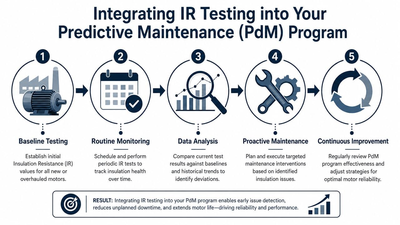
A practical PdM workflow usually includes these actions:
- Baseline every new or overhauled critical motor. Without a starting point, future readings have less value.
- Trend corrected values in the CMMS or reliability database. Raw notes on paper don't support fleet-level decisions.
- Review criticality with condition. A declining non-critical utility motor and a declining production bottleneck motor should not receive the same priority.
- Tie the reading to the failure mode. Cleaning, drying, repair planning, and environmental correction are different jobs. The data should point to the right one.
- Use companion technologies where needed. VFD motors, repeated failures, and conflicting symptoms call for more than one test method.
Teams looking at the broader business case often find that electrical preventive work pays for itself by reducing emergency labor, collateral damage, and rushed procurement. A practical non-technical discussion of that mindset appears in how preventative electrical service saves money, and the same logic applies strongly to motor fleets in industrial plants.
A mature program also connects insulation data with work execution standards, repair scope, and asset strategy. That's where maintenance planning, outage alignment, and condition-based decisions become part of normal plant practice rather than special projects. For teams building that structure, broader guidance on operations and maintenance strategy helps connect individual test results to plant-level reliability performance.
Motor insulation resistance testing earns its value when it becomes a managed process. Baseline. Correct. Trend. Interpret. Act. That sequence prevents more failures than any single pass-fail threshold ever will.
A strong motor testing program catches moisture, contamination, insulation aging, and VFD-related blind spots before they become production losses. If a plant needs help building that program, trending critical motor data, or deciding which assets need deeper electrical diagnostics, Forge Reliability offers a free reliability assessment to identify the highest-risk equipment and the most practical next steps.