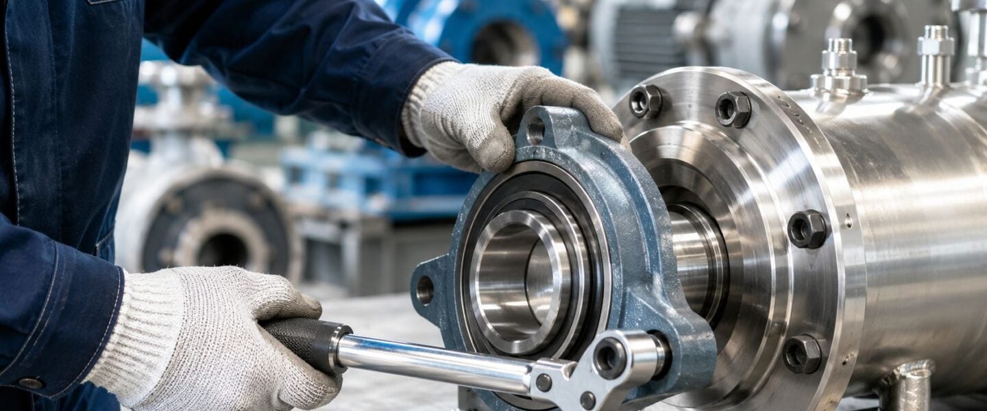
A pump rebuild can pass a visual inspection, receive a new bearing, and still return to the maintenance backlog before the next planned outage. The usual clues arrive gradually: rising vibration, a warmer bearing housing, grease that darkens too soon, or a seal that starts leaking before the bearing's expected service life. By then, the installation error is often buried under weeks of operating history.
The bearing mounting flange deserves more scrutiny than a fastener checklist provides. The mating face, pilot engagement, housing and shaft fits, bolt-load sequence, and shaft alignment determine whether the bearing runs freely or carries hidden preload from the first rotation. The following field guide treats flange mounting as a rotating-equipment reliability task, not a simple bolting operation.
Table of Contents
- Why Bearing Mounting Flange Problems Start Before Installation
- Choosing the Right Bearing Mounting Flange Design
- Verifying Mounting Surfaces and Fit Selection
- Installing and Aligning the Flange Bearing Correctly
- Lubrication, Sealing, and Environment Considerations
- Troubleshooting Common Bearing Mounting Flange Failures
- Inspection Intervals and When to Call in Reliability Support
Why Bearing Mounting Flange Problems Start Before Installation
A process pump returns from rebuild with a new flange-mounted bearing. The shaft turns by hand, the bolts are tight, and the unit passes its initial run test. Several weeks later, vibration begins to trend upward. The operator notices a warmer bearing housing during extended operation, while the maintenance team sees grease discoloration and accelerated seal wear. The bearing may be blamed first, but a distorted flange face or poor shaft squareness can produce the same symptoms without any defect in the rolling elements.
The mounting surface can look acceptable and still impose stress on the housing. A burr under one flange ear, a raised weld spatter, or a frame that is not rigid enough can create soft foot, a condition in which the housing does not sit evenly and becomes distorted as the bolts are tightened. That distortion changes the bearing's internal geometry and can create edge loading, which concentrates contact near one side of a raceway.
The real starting line
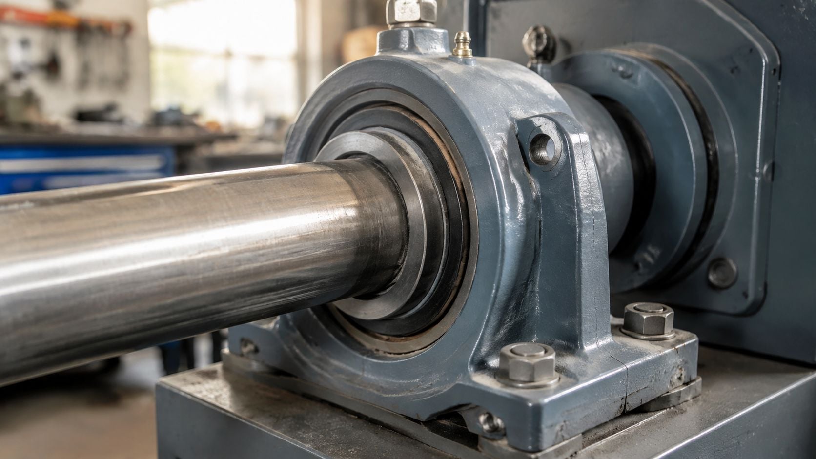
For mounted bearing units, the mounting face should be as flat and smooth as possible. NTN specifies 0.1 mm maximum flatness, with 0.05 mm preferable, and says the housing should sit stably without play. The angle between the mounting face and the shaft should remain within ±2° maximum, with tighter limits for narrower outer-ring types and covered units, as described in its mounted bearing handling guidance.
Those limits aren't academic. A flange that sits at an angle forces the shaft and bearing to operate with misalignment. The resulting loads can appear as a bearing failure only after thermal growth, vibration, and repeated starts have amplified the original installation error.
Practical rule: A bearing mounting flange should be inspected as part of the machine structure. Replacing the bearing without checking the face, pilot, and shaft relationship simply preserves the failure mechanism.
ISO 3548-1:2022 reinforces the same principle from a dimensional standpoint. The standard covers thin-walled plain bearings with integral flanges up to an outside diameter of 250 mm, and non-flanged versions up to 500 mm. It also specifies ISO 286-2 H6 housing tolerances, adequate interference between the bearing outside diameter and housing, and a flange outside diameter smaller than the shaft shoulder and housing block diameters. These requirements make clear that flange geometry, retention, clearance, and installability must work together, especially in compact pump, fan, and retrofit assemblies. The standard is available through this ISO 3548-1:2022 technical sample.
A useful root-cause habit is to classify the contributing factors before ordering another bearing. Teams can use contributing-factor analysis to separate component condition from installation, design, environment, and maintenance causes.
Choosing the Right Bearing Mounting Flange Design
Bolt count changes how a flange housing resists moment loads, housing distortion, and uneven support. Mounted flange bearing products are commonly organized into 2-bolt, 3-bolt, and 4-bolt designs. Four-bolt units use four mounting holes arranged radially around the bearing axis, giving the housing a broader mechanical connection to the frame or panel. The industry guide to flange-mounted bearings describes these configurations and their role in wall-mounted and frame-mounted shaft arrangements.
A two-bolt oval unit can be a sensible choice where space is tight and the load is modest. It also has fewer fasteners to service. The trade-off is a smaller support footprint and greater sensitivity to bolt loosening or frame flexibility when the shaft applies a significant overturning moment. A three-bolt design distributes support around a triangular pattern and can fit applications where a round or compact housing is preferred.
Four-bolt designs generally provide the stiffest interface of the three common patterns. That doesn't make every four-bolt unit suitable for every application, because a rigid housing bolted to a distorted frame can transfer distortion directly into the bearing. The bolt pattern improves the potential stiffness of the connection, but it can't compensate for a poor mating surface.
Flange bolt patterns and typical use cases
| Bolt Pattern | Typical Load Range | Misalignment Tolerance | Common Applications |
|---|---|---|---|
| 2-bolt | Light to moderate duty, subject to the manufacturer's rating | Most sensitive to flexible frames and moment loading | Compact conveyor ends, light fans, small pumps |
| 3-bolt | Moderate duty where support must fit a compact or asymmetric frame | Intermediate sensitivity, dependent on orientation and frame rigidity | Vertical panels, compact gearboxes, selected fan and pump mounts |
| 4-bolt | Higher structural demand and greater moment resistance | Best interface stiffness, but still dependent on surface accuracy | Industrial pumps, process fans, conveyor drives, motor and gearbox end plates |
Boundary dimensions for many flanged housings conform to international standards such as ISO 3228:1993 and, for certain series, JIS B 1559-1995, according to the technical catalog cited in the industry guide above. Standardized families can simplify spare-parts governance across several plants, but a familiar designation doesn't guarantee that every housing detail will interchange.
Maintenance planners should verify the bolt-hole spacing, flange outline, pilot dimensions, shaft bore, locking arrangement, and housing material against the original drawing. SKF distinguishes flanged ball bearing units built to North American standards, where housing boundary dimensions follow ABMA 14 and width tolerances follow ISO 9628, from housing lines that aren't standardized nationally or internationally. That contrast is documented in SKF's North American flanged unit information.
For a structured selection review, maintenance teams can use this bearing selection and installation resource alongside the equipment drawing and load history. The choice should reflect the mounting plane, frame stiffness, vibration exposure, service access, and interchangeability requirements, not just the number of holes.
Verifying Mounting Surfaces and Fit Selection
The best bearing can fail early when the surface beneath it is wrong. Before the first fastener touches the flange, the maintenance team should confirm that the support face is clean, flat, square to the shaft, and strong enough to maintain its geometry under operating load.

Inspect the face and pilot
Start with a visual inspection under good lighting. Remove burrs, raised paint, old gasket material, corrosion scale, and weld spatter. A straightedge and feeler gauges can identify a high spot, while a surface plate or suitable flatness measurement method can confirm whether the face meets the equipment or housing requirement. If the pad is outside the acceptable condition, machining or careful dressing is preferable to forcing the housing into position with bolt torque.
Check squareness with a dial indicator, precision square, or alignment setup appropriate to the machine. The question isn't merely whether the flange face looks vertical. It is whether the bearing axis will remain aligned with the shaft axis after the housing is seated and loaded.
A pilot, also called a spigot, locates the housing concentrically in a matching counterbore. If the design includes one, clean both surfaces and confirm full engagement without rocking. A damaged or loose pilot can leave the bolts carrying a locating function they weren't designed to provide.
Select the fits deliberately
For flange-mounted radial ball bearings, a common housing approach uses an H7 housing bore with a light transition or clearance relationship to the bearing outside diameter. For a bearing with a 35 mm outside diameter, the cited installation guide identifies a possible fit range from 0.009 mm clearance to 0.016 mm interference, depending on the actual bearing outside-diameter tolerance. The correct choice depends on rotation, load, temperature, and housing design, so the fit should be selected from the bearing and machine requirements rather than copied from a previous repair. The dimensional example and cross-pattern tightening guidance appear in this flange bearing installation guide.
On the shaft, j5, k5, or m5 fit classes may suit light-to-normal radial loads where inner-ring creep must be controlled. Creep is relative movement between a ring and its mating surface. It can polish the shaft, generate fretting debris, and change the fit during service.
NTN-SNR specifies an H8 housing-seat tolerance, IT7 bolting-surface flatness relative to the housing-foot diagonal, and a recommended surface roughness of Rz ≤ 100 µm for its flange-mounted housing guidance. It also specifies maximum shaft misalignment of ±0.5° for the referenced housing arrangements. These values give a practical baseline for pump and fan baseplate inspections, but the applicable housing drawing remains the controlling document. The guidance is available in the NTN-SNR bearing housing documentation.
A useful equipment example is a wastewater pump mounted against a fabricated end plate. If the plate has a weld pull that prevents full pilot seating, tightening the bolts can preload the bearing before the pump starts. A measurement of the pilot, face, shaft, and bore catches that condition while correction is still inexpensive. For dimensional context on a common bearing size, maintenance teams can review 6202 bearing sizing information.
Installing and Aligning the Flange Bearing Correctly
Installation should preserve the geometry established during inspection. The housing must seat squarely, the shaft must enter without forcing the bearing sideways, and the fasteners must clamp the flange evenly. An impact wrench may be fast, but it can hide a seating problem and introduce uneven bolt load.
Use a controlled mounting sequence
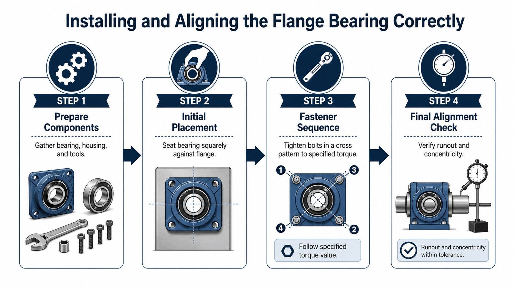
Prepare the components. Confirm the bearing, housing, shaft, pilot, fasteners, washers, locking arrangement, and tools. Clean the shaft and mounting face without pushing debris into the seals.
Seat the housing. Engage the pilot if the design has one. If there is no pilot, position the housing from measured references rather than allowing bolt clearance to determine concentricity. Start all fasteners by hand so the flange can settle naturally.
Tighten across the pattern. Use a cross-pattern sequence, moving between opposite bolts instead of tightening around the perimeter. Bring the bolts gradually to the specified torque in controlled passes. This reduces flange distortion and prevents one corner from pulling the housing down before the opposite side is supported.
Secure the inner ring. Apply the specified locking method only after the housing is seated. A set-screw system, eccentric collar, or other locking arrangement has different installation requirements. The shaft should rotate freely by hand after locking, with no binding or sudden tight spot.
The fastener hole tolerance itself can affect repeatability. SNR documentation shows that mounting-hole tolerance depends on housing size and may reach ±500 µm or ±1000 µm in certain series. During repeated removal and reinstallation of a motor or gearbox bearing unit, that clearance can allow the housing to return to a slightly different position unless the pilot or a documented alignment method controls it. The tolerance information appears in the SNR operating and maintenance manual.
Verify alignment under real conditions
Measure shaft runout before installation where possible, then check the assembled shaft with a dial indicator. Runout is the total indicated movement as a shaft or reference surface rotates. Excessive runout can create seal wear, cyclic loading, and vibration even when the flange face is flat.
Check angular misalignment between the mounting face and shaft, then assess parallel or offset misalignment between coupled components. SKF's maintenance guidance limits initial alignment error in relubricatable cast iron housings to ±2° for bearing size 211 and smaller and ±1.5° for larger sizes, as stated in its maintenance handbook.
After the first operating cycle, inspect temperature, vibration, and fastener condition. Thermal stabilization can expose a frame or shaft relationship that looked acceptable when cold. A post-run check should confirm that the flange remains seated and that re-torque is performed only when required by the manufacturer's procedure, not automatically applied in a way that distorts the housing.
For a pump train, alignment verification should include the shaft coupling and adjacent bearing supports. The practical consequences of shaft angular and parallel error are covered in this guide to shaft misalignment.
Lubrication, Sealing, and Environment Considerations
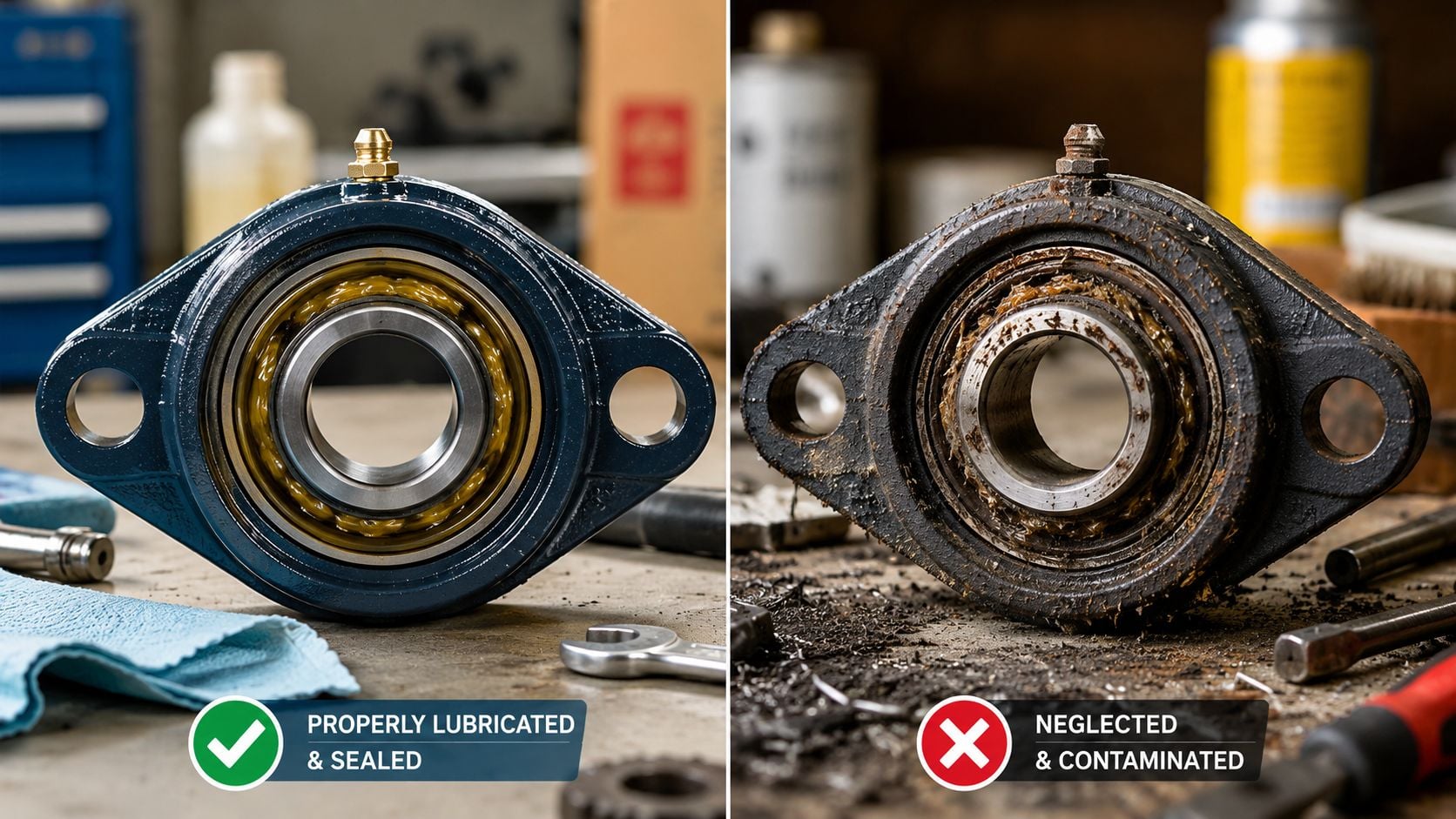
A correctly installed flange bearing still depends on a lubrication and sealing strategy that matches the machine. Grease selection should account for speed, temperature, load, water exposure, chemical contact, and compatibility with the existing lubricant. A generic relubrication instruction can over-grease a slow, heavily sealed bearing or under-protect a wet process pump.
Seal contact is a trade-off. A tighter contact seal can exclude water and abrasive particles, but it also creates more friction and heat. A less aggressive seal may run cooler, yet allow contamination to reach the raceways in a washdown or dusty environment. The right arrangement depends on the contaminant path and the consequence of contamination, not on the seal label alone.
Match the maintenance method to the asset
For a relubricatable cast iron housing, the team should establish the grease type, quantity, purge path, and interval in the maintenance plan. SKF's guidance on initial alignment limits applies specifically to cast iron housings intended for relubrication, which is a reminder that housing type and service method belong in the same equipment record.
An automated greasing system can help where access is difficult or manual intervals are missed, but it won't correct a blocked relief path, incompatible grease, damaged seal, or contaminated housing. The system should be validated against the bearing manufacturer's lubrication requirements. A maintenance planner evaluating that approach can review an automatic greasing system as part of the broader lubrication strategy.
Consider a process fan installed outdoors near a dusty material-transfer area. A seal mismatch can draw abrasive material into the bearing, while excessive grease creates heat that resembles an alignment fault. The diagnostic response should compare vibration, temperature, grease condition, seal wear, and environmental exposure before the bearing is replaced.
Control contamination at the flange
Indoor motor mounts often face dust, washdown residue, or cleaning chemicals through the shaft path and housing joint. Outdoor pumps and fans add rain, condensation, and thermal cycling. The flange face, pilot, seal lips, and grease fittings should be protected during installation and inspected for paths that let contaminants bypass the housing.
Lubrication records should include the actual grease used and the condition of purged grease. A sudden change in color, texture, or odor can support a contamination diagnosis, but it should be interpreted with vibration and temperature data rather than treated as proof by itself.
Troubleshooting Common Bearing Mounting Flange Failures
Recurring flange-bearing failures usually point to a process problem, not a run of defective bearings. The fastest diagnosis compares the failure pattern with the installation record, surface measurements, fit condition, and operating data. A pump that repeatedly fails on the same side of the shaft deserves a mounting investigation before another replacement is approved.
Match symptoms to likely causes
| Symptom or finding | Likely mounting-related cause | Corrective action |
|---|---|---|
| Rising vibration with localized raceway wear | Housing distortion, edge loading, or angular misalignment | Inspect flatness and squareness, verify pilot seating, and repeat alignment measurements |
| Polished shaft or fretting debris near the inner ring | Loose shaft fit or inadequate locking | Measure the shaft and inner ring, select the correct fit, and inspect the locking method |
| Outer-ring movement or fretting at the housing seat | Housing fit too loose for the application | Confirm the housing bore and interference requirement, then correct the housing or replace the unit |
| Early seal wear on one side | Shaft runout, housing angle, or distorted flange | Measure runout and shaft angle, inspect the seal path, and correct the mounting geometry |
| Heat after bolt tightening | Hidden preload from a burr, high spot, or uneven face | Remove the housing, clean or machine the pad, and reinstall with controlled cross-pattern torque |
| Fastener loosening or cracked flange ears | Flexible support, unsuitable bolt pattern, or uneven load sharing | Strengthen the frame, reassess the flange design, and check the bolt pattern against the load direction |
Multiple fit references warn that overly loose shaft or housing fits can cause corrosion, excessive wear, poor rotation, vibration, and noise. The appropriate housing fit depends on whether the ring is stationary or rotating relative to the load. Standard stationary outer-ring arrangements may use looser fits such as G7, H7, or H8, while high-vibration conditions can require interference fits for both rings. The application guidance is summarized in this shaft and housing fit reference.
Use condition data instead of guesswork
Vibration frequency and direction can help separate imbalance, coupling error, looseness, and bearing damage. A mounting problem often produces a combination of symptoms: harmonics associated with looseness, increased broadband energy, a temperature trend, and visible fretting at the flange or shaft. The exact signature depends on speed, load, machine design, and sensor placement, so the trend should be compared with a known-good baseline.
Lubricant evidence adds context. Shiny particles may support a wear diagnosis, while grease contamination near a seal may indicate environmental ingress. Neither finding proves that the bearing was the original cause. The housing face, pilot, shaft fit, and bolt-load record still need inspection.
An emergency repair team often makes the same mistake twice. It replaces the unit, tightens the bolts in a convenient perimeter sequence, skips runout measurement, and returns the pump to service. The repair may restore production briefly, but it also removes the best opportunity to measure the failed interface. During the next shutdown, retain the failed housing, photograph fretting and wear patterns, and record the mounting dimensions before cleaning the evidence away.
Inspection Intervals and When to Call in Reliability Support
Inspection frequency should follow asset criticality, operating severity, and failure history. A bearing mounting flange on a standby fan doesn't demand the same attention as one supporting a continuously loaded process pump, but both need an installation baseline and a clear response plan.
At commissioning or after a major rebuild, record the flange-face condition, pilot fit, shaft runout, bearing temperature, vibration spectrum, fastener condition, and lubrication state. The record should identify the bearing and housing configuration, shaft fit, mounting-face measurements, torque method, and any deviations accepted during the work.
Build a condition-monitoring loop
Vibration analysis is useful for detecting developing looseness, misalignment, and rolling-element damage before the bearing seizes. Thermography can identify an abnormal temperature relationship between similar machines, while ultrasound can support lubrication and seal investigations. Oil analysis applies where the bearing arrangement uses an oil-lubricated housing or shares contamination concerns with an adjacent system.
The monitoring interval should be risk-based. Critical assets may need frequent route or continuous monitoring, while stable, low-consequence equipment can follow a less intensive schedule. A fixed calendar interval without a criticality review can miss a fast-developing fault on a high-duty pump and waste effort on equipment with little consequence.
Escalation signal: Repeated bearing replacement without a documented surface, fit, alignment, and failure-evidence review is a recurring-failure problem, not a parts problem.
A deeper root-cause investigation is justified when identical equipment fails in the same location, when a flange remains misaligned after repeated adjustments, or when vibration returns soon after a bearing change. The investigation should examine design, installation, operation, lubrication, contamination, and maintenance execution. FMEA, criticality ranking, and root-cause methods can then turn the findings into revised work instructions, spare-parts rules, and inspection points.
Strengthen the people and process
Some plants need additional technical capacity for route-based vibration, precision alignment, or failure analysis. Teams assessing hiring reliability engineers can use that resource to define the skills required for rotating-equipment support, especially when recurring flange failures span multiple sites.
Forge Reliability provides predictive maintenance, condition monitoring, reliability consulting, and root-cause failure analysis for equipment such as pumps, motors, gearboxes, fans, and other rotating assets. Its engineers can assess flange mounting practices alongside vibration, thermography, ultrasound, lubrication, alignment, and maintenance-program data, helping plant teams identify whether the recurring fault starts at the bearing, the mounting interface, or the wider machine train.
Schedule a free reliability assessment with Forge Reliability to review a recurring bearing mounting flange failure, inspect the installation and alignment process, and connect field measurements with condition-monitoring data. The assessment can help maintenance and operations leaders prioritize corrective work on pumps, fans, motors, and gearboxes before another preventable flange-related outage.