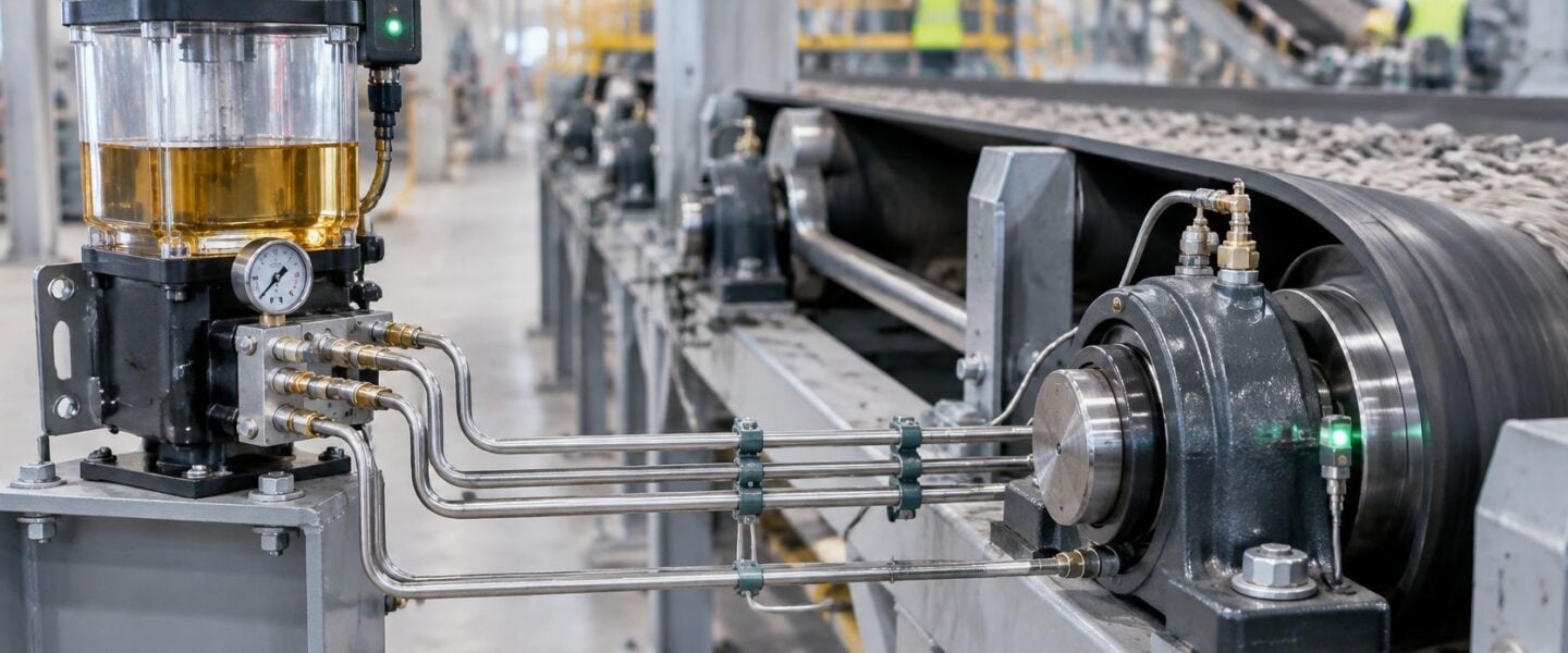
The most popular advice on automatic lubrication is also the most dangerous version of it. Fit a pump, set a timer, watch it cycle, and the bearings are handled. They're not. A cycling pump proves the motor ran and the main line built resistance. It doesn't prove that grease crossed the last fitting, entered the housing, and reached the rolling elements in the right quantity.
That's the distinction reliability teams have to hold. A central lubrication system can remove missed points, inconsistent manual doses, and routine access to guarded or hard-to-reach bearings. It can also create a quiet common mode failure, where one wrong grease, one dirty reservoir, or one blocked feeder starves points while the panel still looks healthy. The deliverable isn't automation. It's point-by-point delivery proof, backed by contamination control and records that let a planner compare today's reading against a verified baseline.
Table of Contents
- Choose the Architecture That Matches the Machine
- Size Each Dose Then Size the Pump
- Prove Grease Arrived and Read False Healthy Cycles
- Keep One Reservoir from Contaminating Every Point
- Set Baselines on a Conveyor and a Dryer
- Set Inspection Intervals and Retrofit Path
- Book a Free Reliability Assessment
Choose the Architecture That Matches the Machine
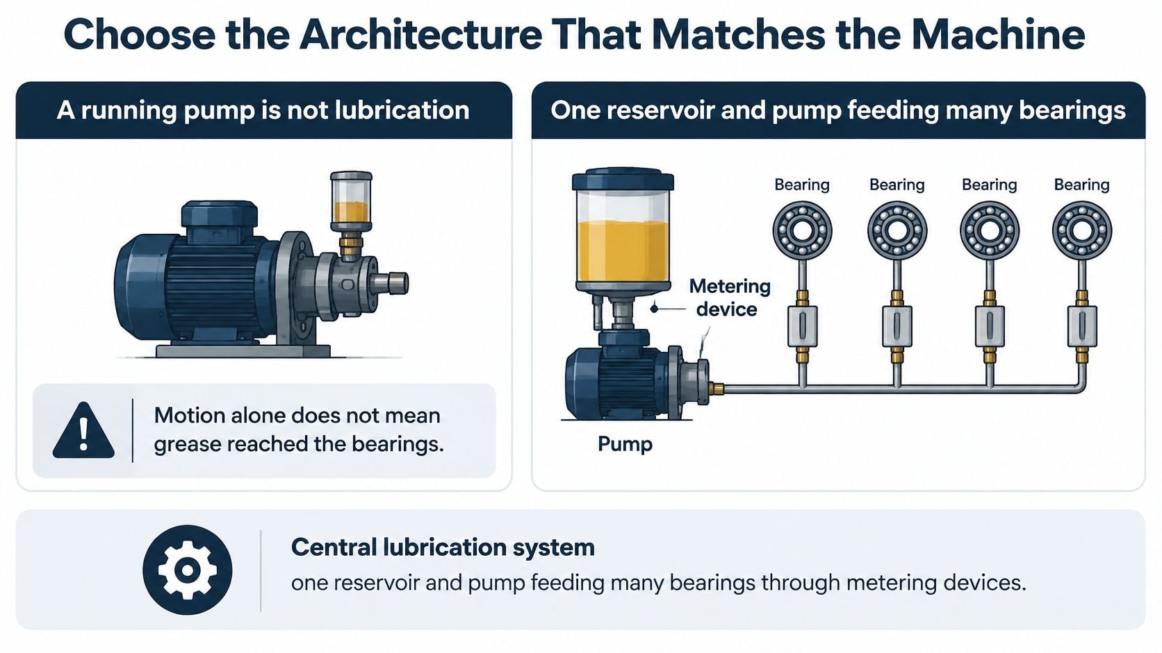
A running pump is not lubrication. A central lubrication system is one reservoir and pump feeding many bearings through metering devices, where a metering device is an injector or feeder that discharges a set volume per pulse. The architecture decides where lubricant goes after delivery, how a blockage behaves, and what a normal signal can confirm.
Architecture Before Pump Catalog
The Plant Services overview of centralized lubrication divides systems into total-loss and circulating-oil arrangements, with total-loss lubricant metered at time or machine-cycle intervals and not recovered, while circulating oil returns to a reservoir for filtration. That split matters more than brand or pump size. Total-loss teams verify dose and arrival. Circulating-oil teams verify return flow, filtration, and cleanliness.
Central lubrication architectures and what a healthy signal proves
| Architecture | Lubricant path | Best industrial fit | Key constraint | A normal signal proves |
|---|---|---|---|---|
| Single-line | Total-loss metered pulses | Modest point counts, fluid grease or oil, food packaging on NSF H1 | Injector size and line length set the dose | Pressure in the main line, not grease at every bearing |
| Dual-line | Total-loss, alternating pressurized lines | Long runs and high point counts on mining, steel, or outdoor equipment | Both lines, changeover valve, and end-of-line pressure must be verified | A line was pressurized, not that every injector discharged |
| Progressive | Total-loss, sequenced through primary and optional secondary feeders | Critical bearings where a blockage should stop the cycle | Up to 550 bar (8,000 psi); do not add a third distribution level | The feeder completed a cycle, not the condition of the bearing |
| Circulating oil | Oil is returned, filtered, and reused | Paper-machine dryer bearings and other assets with return piping | Filtration, reservoir cleanliness, and return flow | Oil circulated, not that every bearing film is adequate |
Four Tests That Settle the Choice
A food-packaging line makes the total-loss case clearly. It needs controlled doses of NSF H1 grease, meaning lubricant approved for incidental food contact, and the spent grease can't return for reuse. Single-line delivery fits because point counts are modest and each dose is consumed at the contact.
A paper-machine dryer points the other way. Dryer bearings already suit return piping, so circulating oil lets the plant filter wear particles and contaminants instead of treating volume per pulse as the main control. Inspection then centers on the reservoir, filters, and return path, not only the outlet.
Before specifying a pump, reliability teams should answer four questions in writing.
- Point count and line length: Long runs and many outlets push the design toward dual-line or a carefully limited progressive network.
- Grease consistency versus oil: NLGI grade, the standard scale for grease stiffness, plus temperature and back-pressure decide whether lubricant will move through the chosen lines. Teams reviewing pump drive options can compare requirements against the guidance on pneumatic grease pumps.
- Silent starvation tolerance: If one dark point is unacceptable, the architecture and monitoring must make a blockage visible.
- Particle removal or total loss: Filtration and reuse justify circulating oil. A metered dose that stays at the point justifies total loss.
Selection rule: Name one architecture for one named asset, and state what its normal signal does not prove, before sizing any pump.
That discipline prevents a common specification error. Teams buy pressure capability first, then discover the machine needed proof at the bearing.
Size Each Dose Then Size the Pump
The metering device decides whether a bearing is fed. The pump creates pressure and volume for the network, but each injector or feeder section sets the quantity that a single point receives. Reversing that order produces strong pumps connected to wrong doses.
The SKF centralized lubrication documentation describes typical metered quantities of 0.01 to 1.5 cm³ per lubrication pulse and lubrication point. Too much grease raises churning losses, temperature, seal stress, and leakage. Too little accelerates adhesive wear, false brinelling, and fatigue, where false brinelling is wear marking from small oscillatory movement without adequate film separation.
Dose Bands for the First Pass
Metered dose bands used to select injectors
| Metering reference | Oil per outlet per pulse | Fluid grease or grease | How to use it |
|---|---|---|---|
| Typical centralized range | 0.01–1.5 cm³ | 0.01–1.5 cm³ | Design envelope for one point and one pulse |
| Series 340 single-line | 0.01–0.16 cm³ | 0.03–0.10 cm³ | Small oil or fluid-grease outlets |
| Series 350 single-line | 0.05–0.60 cm³ | 0.10–0.30 cm³ | Larger oil doses and mid-range fluid grease |
| Typical grease-system target | 0.1–0.3 cc | 0.1–0.3 cc per point per cycle | Commissioning check, then pressure-test at 1.5 times working pressure |
The lower grease-system band and commissioning test also appear in the technical grease-system guide, which gives 0.1–0.3 cc per lubrication point per cycle and recommends pressure testing at 1.5 times working pressure before commissioning. Those numbers are brackets, not substitutes for bearing demand. A small high-speed bearing and a large slow pivot shouldn't inherit the same dose because their fittings look alike.
Sizing Sequence
- Collect the point data: Record bearing speed, load, temperature, lubricant viscosity or NLGI grade, contamination exposure, and the manufacturer relubrication guidance for each outlet.
- Convert demand to a pulse: Turn the required quantity per interval into cubic centimetres per pulse, using the intended pulse count rather than a convenient timer setting.
- Bracket the dose: Select a fixed or adjustable feeder whose output range brackets that point's requirement, not the neighboring bearing's requirement.
- Sum the network: Size pump displacement as the sum of all outlet doses multiplied by pulses per hour, plus margin for line fill and compressibility.
- Check movement, not pressure alone: Assess line length, grease consistency, ambient and bearing temperature, and back-pressure together before release.
On a cement-plant conveyor, unequal hose lengths expose weak sizing quickly. If short runs show fresh grease and long runs stay dry, changing injector size or line routing addresses distribution. Raising pump frequency only overfeeds the points that were already receiving grease.
Commissioning should verify delivered mass or volume at representative outlets, including the longest and highest runs. The CMMS record needs outlet identity, dose, pulse count, interval, lubricant grade, and bearing temperature. An unexplained temperature rise after startup triggers checks for excess dose, incompatible grease, blocked venting, or a restricted outlet before anyone shortens the interval.
Prove Grease Arrived and Read False Healthy Cycles
Reservoir level can fall, pressure can look normal, and one bushing can still run dry. A blocked injector, collapsed hose, trapped air pocket, wrong injector size, or unequal line length breaks the link between pump activity and bearing delivery. Verification has to close that gap at the terminal point.
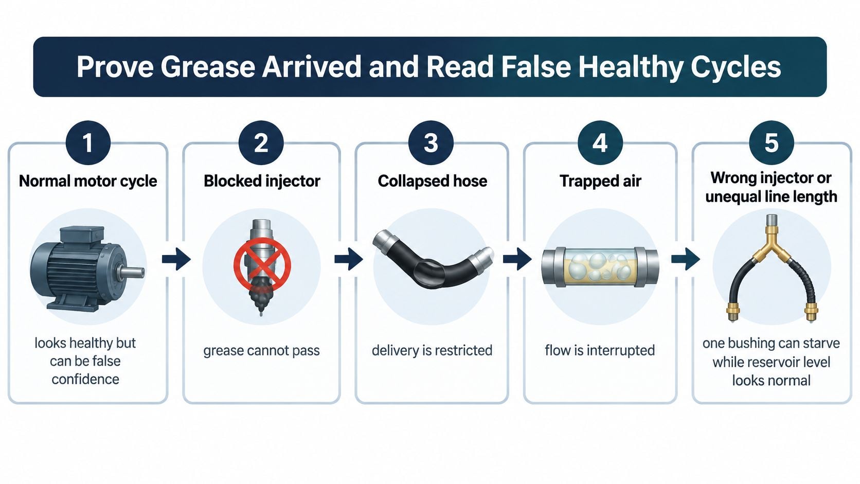
Verification Steps
- Map every outlet: Tie each outlet to a bearing or bushing and name the failure mode that starvation or overgreasing would produce there.
- Bleed each circuit: Continue until lubricant flows consistently without air bubbles at the point being commissioned.
- Measure at the terminal point: Confirm delivered volume where the line meets the asset, not only at the pump discharge.
- Alarm incomplete cycles: Fit a cycle switch or position sensor on a progressive feeder and alarm when the expected cycle isn't completed within a defined time window.
- Trend the system signals: Record pump current, pressure response, cycle duration, reservoir consumption, and bearing temperature in the CMMS or historian.
The SKF progressive systems page states that pump pressure can reach 550 bar (8,000 psi) and that adding a third distribution level is not recommended. Progressive sequencing helps because a blocked section can stop progression and create an identifiable fault. It doesn't excuse weak grease selection, excessive line resistance, or a cycle alarm that nobody trends.
A gradual rise in cycle time suggests rising line resistance, hardening grease, contamination, or a weakening pump. An immediate no-cycle alarm points first to empty reservoir, broken line, blocked feeder, or lost drive power. Those signals gain value when correlated with condition data through routes such as ultrasonic bearing monitoring and acoustic lubrication, because friction changes often appear before temperature becomes a dependable warning.
The Graco blocked-line technical document identifies blocked or pinched lines as a condition where the system continues working while individual bearings receive no lubricant. On an injection-molding machine, that failure can leave one bearing starved during every normal-looking motor cycle. A rupture-to-atmosphere indicator, a sacrificial warning device that vents when pressure becomes abnormal, paired with a pressure switch can flag the fault while other points continue feeding, and replacement of the indicator helps confirm that the blockage has cleared.
Lubrication symptoms that mimic a healthy cycle
| What you see | What it does not prove | Likely mechanism | First check |
|---|---|---|---|
| Pump cycles and one bearing runs hot | Grease reached that bearing | Blocked or pinched line while other points still feed | Compare cycle count to the pressure switch and inspect the line |
| Pressure spike above the baseline | A normal cold-start peak | Frozen metering device or collapsed distribution line | Compare with the 1.5-times commissioning pressure record |
| Uneven grease at outlets | A bad bearing | Wrong injector size or unequal line length | Measure delivered volume at each outlet |
| Leak at a threaded fitting | Over-lubrication | Poorly sealed or over-tightened connection | Reseat the fitting and recheck neighboring points |
| Fresh grease at the seal and rising temperature | Starvation | Excess dose, incompatible grease, blocked vent, or restricted outlet | Compare dose and grade with the CMMS record |
| Immediate no-cycle alarm | The bearing has already failed | Empty reservoir, broken line, blocked feeder, or loss of drive power | Check level, drive power, and feeder indicator before the asset |
Pressure proves resistance in a circuit. It doesn't prove grease arrived at the rolling elements.
When point verification fails, teams should redesign tubing or metering. Increasing pump frequency masks the distribution fault and punishes every healthy outlet.
Keep One Reservoir from Contaminating Every Point
Manual greasing fails one point at a time. A centralized reservoir can fail dozens at once. Missed lubrication usually declines after automation, but one dirty fill, one incompatible product, one failed pump, or one hidden blockage becomes a common-mode failure, meaning a single cause defeats multiple assets that looked independent.
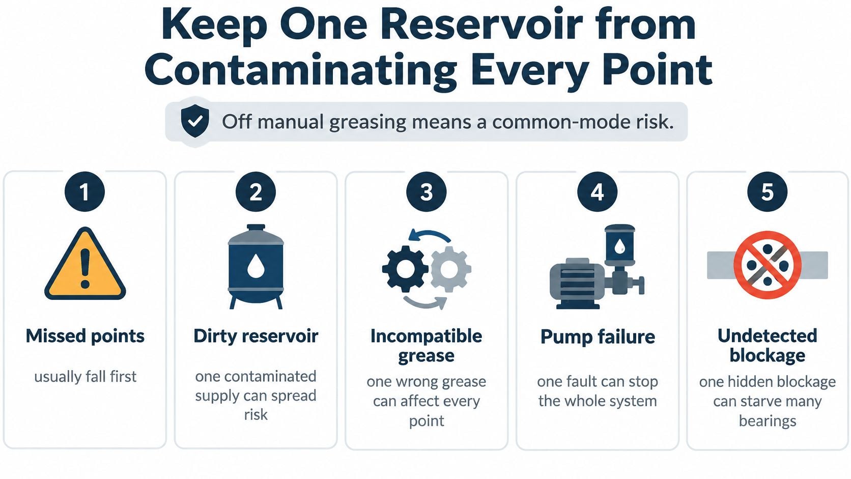
Where the Risk Concentrates
The central lubrication guide from Hymalube emphasizes keeping reservoirs clean and dry, avoiding simultaneous use of incompatible lubricants, and inspecting filters and lines. That's not housekeeping advice. Mixed greases can harden or soften, water in a reservoir travels to every injector, and debris in circulating oil returns through the loop until filtration removes it.
Food and beverage washdown adds moisture and NSF H1 product control. Mining and outdoor equipment add dust, shock, and wide temperature swings. Chemical processing adds product compatibility and exposure concerns. Each environment changes how grease moves and how quickly a reservoir becomes contaminated.
Comparison with manual work should use total risk, not labor saved. Legacy points left on manual routes still need the same product discipline, including control of the grease gun tube used for top-ups, so a technician doesn't introduce a second grease into a housing now fed centrally.
Commissioning and Governance Checklist
- One product per system: Label the reservoir with product, grade, and approved transfer container.
- Compatibility before changeover: Test the new product against the residual grease before any fleet-wide switch.
- Flush, don't chase: Flush lines during conversion instead of pushing old grease ahead of new grease into bearings.
- Clean transfer: Use dedicated, closed transfer equipment and keep the reservoir closed and dry between fills.
- Filtration and low level: Fit reservoir filtration where the architecture supports it and alarm low level before air enters the pump.
- Spares by criticality: Stock pumps, feeder sections, injectors, and rupture indicators according to failure consequence.
- CMMS traceability: Store lubricant grade, batch, fill date, flush date, and point criticality against the system asset.
Pressure sensors, flow monitors, cloud connectivity, and consumption trends help only after validation against bearing condition. An alarm that matches pump status but misses starvation gives management a cleaner dashboard and the plant the same failure.
Startup should wait if the reservoir can't be shown clean, dry, and filled with one verified product. That delay is cheaper than distributing a known contaminant efficiently.
Set Baselines on a Conveyor and a Dryer
Say a cement plant runs a long conveyor and crusher bearing network on total-loss grease. Dust coats the frames, impact loading works fittings loose, and hose runs to idlers and pulleys differ sharply in length. Identical fittings on that machine don't justify identical assumptions about delivery.
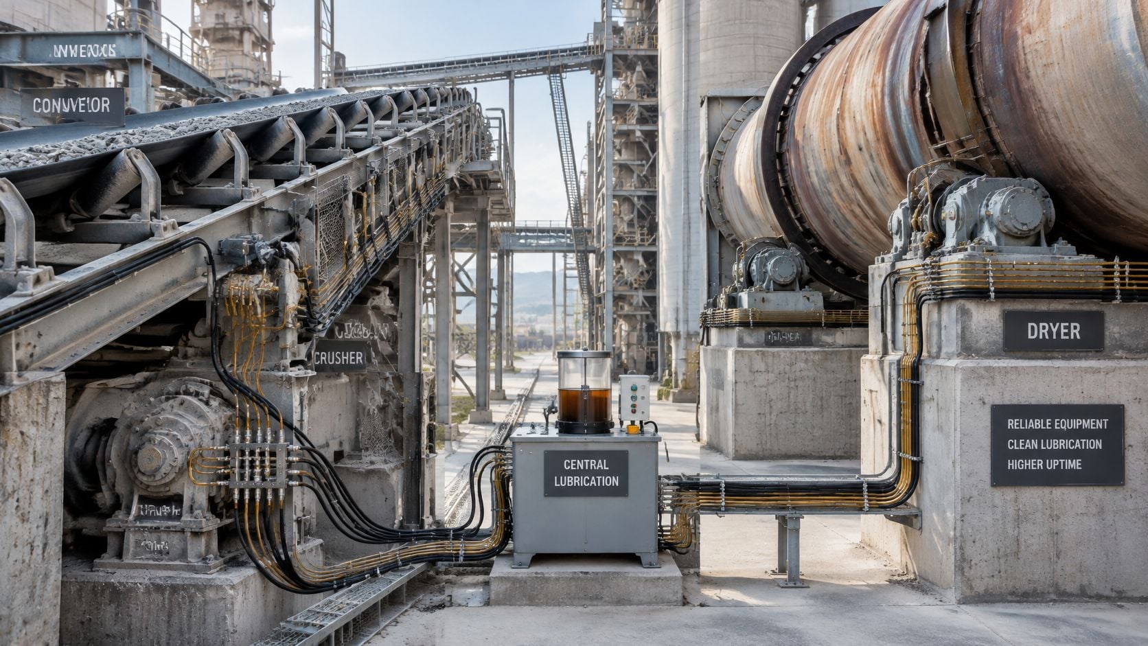
Cement Conveyor Baseline
The commissioning file for each outlet should capture test pressure, injector size, line length, and delivered volume. Later, a pressure spike or hot bearing can be compared with that known state instead of opinion. Route inspection looks for pinched lines at idler frames, hardening grease during cold starts, damaged fittings, and reservoir consumption that no longer matches pulse count.
Conveyor lubrication also sits beside belt, pulley, and rolling-component decisions. Planners coordinating the wider asset route can use the Material Handling USA conveyor wheel guide for conveyor wheel context, while the plant's own program for conveyor belt maintenance, tracking, and splicing keeps belt condition from being confused with bearing lubrication faults. Ultrasound or temperature checks belong on critical cement bearings when cycle time starts creeping upward.
The single record that makes later diagnosis possible is the outlet baseline. Without delivered volume by point, every future adjustment becomes trial and error.
Paper Dryer Baseline
A paper-machine dryer section on circulating oil needs a different first record. Return flow, filter condition, and particle removal matter more than pulse volume. A blinded filter or low reservoir is a system-level event because the same oil serves the loop repeatedly.
Oil analysis and filter differential pressure, the pressure drop across a filter element, belong on the dryer route. Rising particle counts or differential pressure call for filtration work before bearing temperatures turn into the first alarm. A brief contrast helps planners avoid copying that model onto food packaging, where total-loss H1 grease remains appropriate because lubricant can't return.
Plants should create the baseline they lack this week. Total-loss owners record outlet delivery. Circulating-oil owners record filter differential pressure and return flow.
Set Inspection Intervals and Retrofit Path
Inspection frequency should follow failure consequence, not calendar habit. A lubrication system feeding a production bottleneck deserves tighter verification than one feeding easily isolated auxiliary bearings. The route also differs by whether lubricant is consumed at the point or returned for reuse.
Building the Interval
- Classify the system: Mark each circuit total-loss or circulating oil in the CMMS, with its critical points and common-mode exposure.
- Start from OEM guidance: Use the manufacturer relubrication guidance as the initial interval for point verification and reservoir condition checks.
- Shorten until trends stabilize: Tighten the route until cycle time, pressure response, and consumption hold steady through a full operating period.
- Add loop-specific checks: On circulating oil, inspect filters by differential pressure and sample oil on the same route so one visit produces connected evidence.
- Test against baseline: Compare delivered outlet results with commissioning records at each verification, a practice that fits naturally into preventive maintenance for lubrication systems.
Interval rule: Extend an inspection only after trend stability proves the circuit still delivers, not after several quiet months on the alarm screen.
Retrofit in Consequence Order
Manual points shouldn't move centrally in the order they're easiest to pipe. Teams should rank bearings by failure cost, access difficulty, and lubrication frequency, then place the highest-consequence points on monitored circuits first. Difficult access strengthens the case only when delivery can be verified after conversion.
Before extending a long dead-end run, planners should confirm line length, injector size, and lubricant grade against the commissioning record. Adding points to an unverified circuit expands the blind spot. A smaller monitored retrofit with proof at each outlet delivers more reliability than a larger network that nobody can audit.
Book a Free Reliability Assessment
A central lubrication system is a maintained asset, not an accessory that can run to failure. Pump, reservoir, metering devices, lines, fittings, and alarms each need functional checks tied to failure consequence. Treating the system as installed infrastructure is how blocked outlets stay invisible until bearing damage supplies the notification.
Three tasks belong in the existing program now. First, route-based PM should include point verification and reservoir condition, not only reservoir refill. Second, cycle time, low level, and pressure tags should enter the historian and connect with ultrasound, vibration, and oil or grease analysis on critical bearings. Third, every bearing failure review should include the lubrication circuit, dose record, and product history instead of stopping at the failed part number.
A free reliability assessment should answer three concrete questions for the systems already installed. Which feeders are mis-sized for their bearings? Which alarms would miss a blocked line while reporting a healthy cycle? Which manual points carry enough failure consequence to justify a monitored circuit?
Those answers turn lubrication automation into an auditable reliability control. Plants that can't answer them from current records don't need a larger pump. They need baseline proof, alarm validation, and a retrofit sequence based on consequence.
Forge Reliability helps reliability and maintenance teams audit central lubrication delivery, validate alarms against bearing condition, and prioritize monitored retrofits for high-consequence assets. Request a free reliability assessment to identify mis-sized feeders, hidden blockages, and contamination risks before they become unplanned downtime. Visit Forge Reliability to start the assessment.