The popular advice is simple. If a motorized valve trips on high current, replace the actuator. If it trips on torque, raise the torque setting. If it passes a full-stroke test at shutdown, assume it's available until the next shutdown.
That advice is fast, and it's often wrong. A high-current alarm usually tells the maintenance team that the mechanical load has changed, not that the motor has suddenly failed. A torque trip tells the team that resistance exceeded a protective setting. Raising that setting without finding the resistance can turn a protective stop into stem, gearbox, or seat damage.
Reliability work on motorized valve actuators starts from a different premise. The actuator, gearbox, coupling, stem, packing, and valve form one electromechanical system. Current, travel time, position, and torque have to be read together against a commissioning baseline. When those signals are trended by direction and position, a nuisance trip becomes useful evidence.
The decisions that follow are practical ones. Which actuator family fits the valve motion. How much torque margin is defensible. Which check confirms a suspected cause. Which test proves an isolation valve will move on demand.
Table of Contents
- Motorized Valve Actuator Types and Where Each Fits
- How to Size an Actuator From the Valve Torque Profile
- Failure Modes That Stop Motorized Valves
- Diagnosing High Motor Current Without Blaming the Actuator
- Setting Torque Trips, Limit Switches and Routine Checks
- Proving Isolation Valves Work Between Shutdowns
- Book a Free Reliability Assessment for Critical Valves
Motorized Valve Actuator Types and Where Each Fits
A motorized valve actuator is an electric motor, gear train, and control package that converts electrical power into the motion a valve needs to open, close, or throttle. Throttling means holding the valve at intermediate positions to control flow, rather than driving it fully open or fully closed. The control package normally includes torque and limit protection, position feedback, and local controls inside a sealed enclosure.
| Actuator type | Valve it moves | Strength | Watch-out |
|---|---|---|---|
| Multi-turn electric | Rising-stem gate and globe valves | High thrust, open-close or throttling | Gearing wear and stem loading |
| Quarter-turn electric | Butterfly, ball and plug valves | Compact quarter-turn travel, fast operation | Breakaway torque peaks and seat sticking |
| Linear electric | Straight-stroke valves and dampers | Direct linear thrust | Stem alignment and side loading |
| Electro-hydraulic | High-thrust and remote high-pressure valves | Very high force from a compact package | Fluid condition and hydraulic leaks |
Valve Motion Decides the Family
Valve motion dictates the actuator family. A rising-stem gate valve requires many turns to lift its stem, so it requires a multi-turn unit. A butterfly valve needs a quarter turn, so a multi-turn unit cannot be mounted on it and expected to travel, indicate, or seat correctly.
Say a food plant runs a 300 mm butterfly valve on a cooling-water header. The right choice is a quarter-turn unit, and the commissioning check that matters most is breakaway torque, the force needed to start the disc moving from the closed seat. A 6-inch rising-stem gate valve on a steam header is a different problem. It needs a multi-turn unit, and the dominant risks are gearing wear and stem thrust over many turns. That steam duty also sits near pressure-relief protection, so planners coordinating isolation work should understand how a steam relief valve protects the same header.
Duty matters as much as motion. An on-off valve that strokes twice a month faces sticking and breakaway risk. A throttling valve that repositions constantly faces motor heating, gear wear, and control drift.
Selection rule: Confirm the valve family and its duty, on-off or throttling, before opening any catalog.
Electro-hydraulic units earn their place where electric units can't deliver enough force in the available space, or where remote high-pressure service justifies managing hydraulic fluid and leak risk. For most plant duties, though, the choice narrows quickly once motion and duty are fixed.
How to Size an Actuator From the Valve Torque Profile
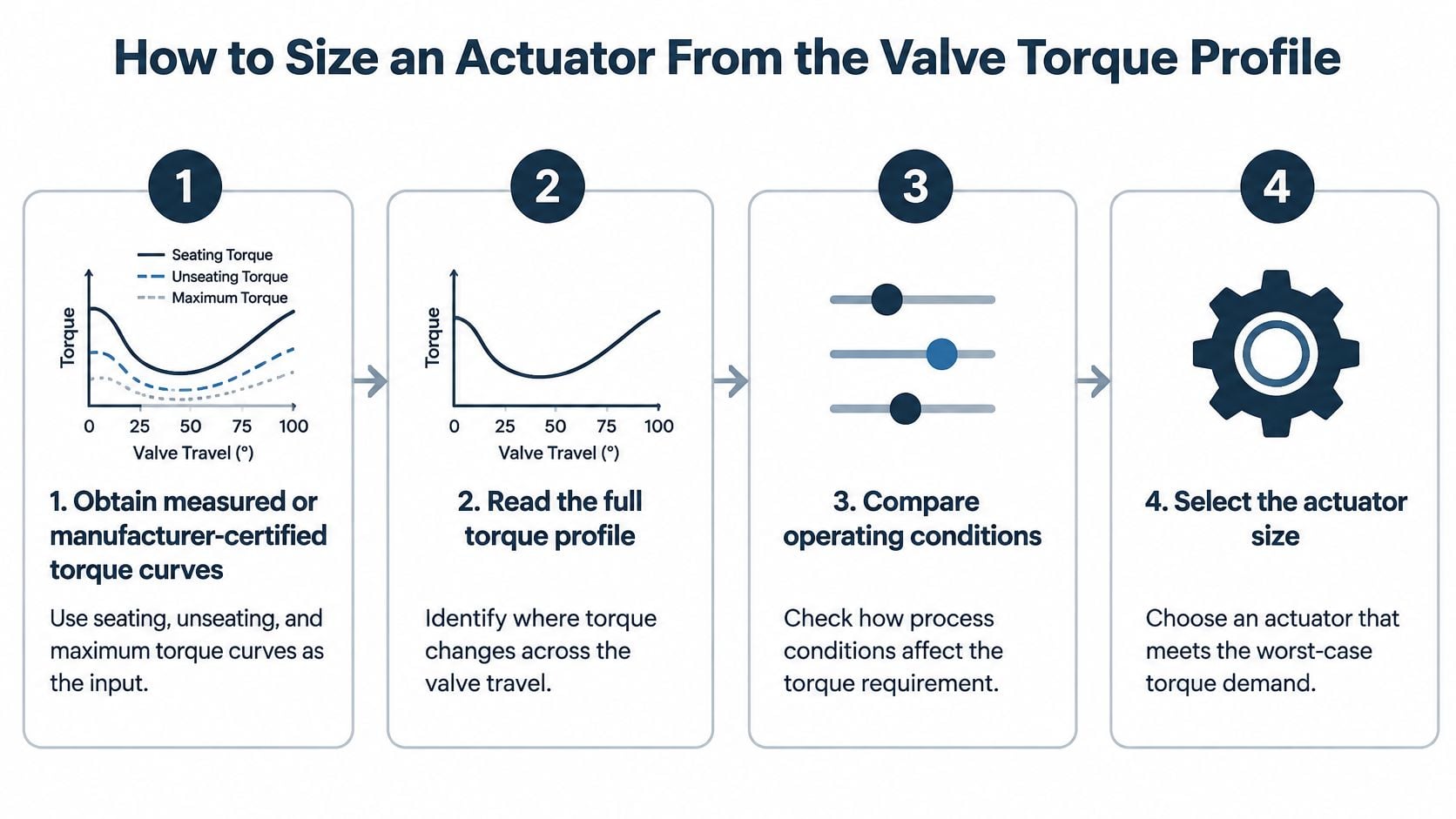
Nominal valve size is the wrong input for actuator sizing. Two valves with the same bore can demand very different torque depending on seat design, differential pressure, and how long they've sat still. Sizing has to start from the valve's complete torque profile, meaning how required torque changes across the full stroke, or the thrust profile for rising-stem valves.
Sizing Steps in Order
- Obtain the torque curves. Get measured or manufacturer-certified curves for seating torque, unseating torque, and maximum dynamic torque at actual process conditions. The AWWA C542 standard requires these torque values to be identified for quarter-turn service, and that requirement reflects sound practice for any critical valve.
- Record what shifts torque demand. Note differential pressure, temperature, packing friction, corrosion, and infrequent operation. Each one moves the required torque, and a valve that sits closed for months can need far more breakaway force than its clean catalogue figure suggests.
- Separate open-close from throttling service. AWWA C542 distinguishes these duties because throttling imposes substantially different operating-frequency and thermal-duty requirements. A motor rated for occasional strokes will overheat if it's repositioning every few minutes.
- Apply a documented design margin. Choose the margin deliberately and write it down. Picking the next size up from a catalog isn't a margin, it's a guess that nobody can audit later.
- Check the allowable load ceiling. Confirm the actuator's maximum output can't exceed what the stem, gearbox, or seat can tolerate. Available torque beyond that ceiling is a damage mechanism waiting for a jam.
- Record the commissioning baseline. Capture open and close torque settings, travel time, position feedback, and motor current at no-load and process-load conditions. That record becomes the reference every future diagnostic comparison depends on.
Both Sizing Errors Cause Failures
An undersized actuator stalls at breakaway or seating. The motor overheats, isolation stays incomplete, the valve leaks, and limit switches trip repeatedly. An oversized unit fails differently. Its available torque can exceed the allowable stem or seat load, and torque-switch protection becomes less discriminating because the trip point sits far from normal running torque.
Consider a 150 mm ball valve on a chilled-water loop in a pharmaceutical plant. Sized as an on-off valve, a modest actuator looks adequate. Put that same valve into throttling duty to hold a temperature loop, and the rating changes completely because operating frequency and motor heating now govern the selection, not peak torque alone.
Failure Modes That Stop Motorized Valves
A motorized valve can stop responding even when its motor is healthy. The cause may be mechanical resistance, a failed electrical connection, or feedback that no longer reflects actual travel. Separating these categories helps maintenance teams identify what to inspect before replacing components.
Mechanical and Drive Failures
Gear wear can increase travel time and operating noise. Compare stroke duration with the commissioning record and check whether the change is consistent across repeated operations. A rising reset count or progressively longer travel time is more useful evidence than a single alarm.
Packing friction or seat damage can also increase the load required to move the valve. If travel time lengthens while the control system reports normal position, inspect the valve's mechanical condition and compare operating records at similar process conditions. Motor heating during throttling duty is a separate operating concern, so focus here on evidence of changing mechanical resistance rather than treating heat alone as proof of actuator failure.
Electrical and Control Failures
Moisture ingress can corrode terminals and cause intermittent control faults, particularly on outdoor or washdown units. Inspect terminal blocks, enclosure seals, and wiring when faults appear intermittently or clear temporarily after a reset. Track reset counts by valve: a rising count in the event log shows that the fault is recurring, even if each reset restores operation for a time.
Control-board faults may cause unexplained resets or loss of network communication. Review event history for resets and communication losses, then check the electrical connections before assuming the board itself has failed. A corroded terminal block, for example, can produce symptoms that resemble a control fault while the underlying problem is at the connection.
Feedback and Position Indication
Limit-switch drift can leave the valve short of its intended position, allow it to overrun, or produce an incorrect open or closed status. Compare local travel with control-room indication to determine whether the switch setting or indication is at fault.
Calibration loss creates a related problem: reported position no longer matches physical stem or disc position. Verify feedback against actual travel before relying on the control system's position signal. A structured FMEA for manufacturing can help rank these failure modes by consequence and guide inspection priorities.
A high motor-current alarm may accompany several of these conditions, but it does not identify the failed component by itself. Compare the alarm with travel time, event history, and position feedback. That correlation helps distinguish a changing valve load from an electrical or feedback fault.
Diagnosing High Motor Current Without Blaming the Actuator
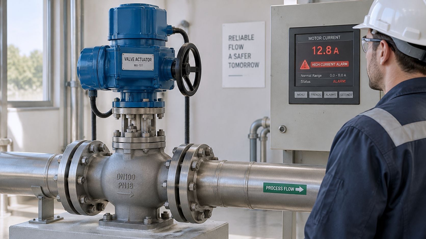
A high-current alarm usually reflects a changing mechanical load. Replacing the actuator in response often repeats the failure, because the new drive faces the same binding stem, tight packing, or rising differential pressure that overloaded the old one. Guidance on understanding valve actuator diagnostics makes the useful distinction that high current can point to motor deterioration, low line voltage, gearbox efficiency loss, seat damage, packing friction, stem misalignment, corrosion, contamination, or increased differential pressure.
| Current pattern | Likely cause | Confirming check |
|---|---|---|
| Higher current at the same position on every stroke | Rising packing friction or stem binding | Manual torque check at the stem and packing gland inspection |
| Current spike at breakaway, normal running current | Seat sticking or debris in the flow path | Compare breakaway torque with the commissioning record |
| Current high throughout, winding temperature rising | Low line voltage or motor deterioration | Voltage-drop test and insulation check |
| Current normal, travel time longer | Gearbox wear or lubrication loss | Gearbox inspection and oil condition check |
| Erratic current, spikes in one direction only | Stem misalignment or coupling damage | Alignment check and coupling inspection |
Read Current Against the Baseline
Current means little as a single number. It has to be trended by direction and by position, then correlated with travel time, torque or thrust, supply voltage, winding temperature, cycle count, and process pressure. A current rise at one repeatable position points at friction or binding at that point in the stroke. A rise everywhere points somewhere else entirely.
Forge Reliability uses valve position trending to identify governor valve hysteresis and sticking, and the same logic applies here. Position-correlated data separates a valve that's hard to move at one spot from a motor that's deteriorating across the whole stroke. In steam turbine service, the key symptom of valve stem binding is sluggish valve response during stroke testing with increased stem force, which is exactly the pattern position and force trending is built to catch.
Once the pattern is clear, targeted tests confirm it. Techniques covered in motor current signature analysis fault detection, along with infrared inspection of terminals, voltage-drop testing, and manual stem torque verification, give enough evidence for a planned intervention instead of an emergency swap.
Say an outdoor chemical-plant isolation valve trips repeatedly and its actuator gets replaced twice. The repair that holds is packing gland adjustment and stem lubrication, which a baseline comparison would've pointed to from the start. The rule is straightforward. Check the valve, coupling, lubrication, and process condition before condemning the drive.
Setting Torque Trips, Limit Switches and Routine Checks
A torque trip is protective. The torque switch stops the actuator when resistance exceeds its setting, so a trip is information about the valve's condition. Raising the limit to make trips go away treats that information as a nuisance, and it's how a jammed valve becomes a bent stem.
Responding to a Torque Trip
- Verify torque demand. Compare the valve's current torque demand against the commissioning baseline before touching any setting.
- Confirm both settings. Check the torque setting and the stroke-limit settings, because an incorrect limit setup can drive the valve into a mechanical stop and mimic a torque problem.
- Clean, lubricate, and clear. Clean and lubricate the stem and check for debris in the flow path. Excessive stem friction and debris are common, fixable causes of abnormal resistance.
- Repeat limit setup after any change. Any torque-limit change requires the stroke-limit setup to be repeated, so the two protections stay coordinated.
Setting Limit Switches Correctly
- Verify before powering. Confirm motor rotation and limit-switch operation before running the actuator under power.
- Check both switches by hand. Manually open the valve to check the open switch, then manually close it to check the close switch, watching for binding or abnormal resistance throughout.
- Allow for coast. After reaching fully open, close the handwheel by one turn before setting the switch. Moving parts coast after the motor stops, and a switch set exactly at the running position can be displaced by that inertia, producing a false end-position indication.
On a power-plant service-water isolation valve, that verification isn't complete until local travel and control-room indication agree. Periodic checks such as motor insulation resistance testing belong in the same routine, since winding condition and switch condition degrade on similar timescales.
Workshop habit worth keeping: Every torque-setting change and every trip goes into the CMMS, or the trend history has holes exactly where the evidence matters.
The Annual Inspection Baseline
Routine work needs a fixed anchor. Emerson's Bettis actuator maintenance instructions specify checking the actuator at least once per year, including disconnecting electrical power, opening the enclosure, inspecting and tightening electrical connections, checking for electrical or mechanical damage, replacing worn components, and checking or recalibrating switch actuation when necessary.
Annual doesn't mean sufficient everywhere. A food-processing washdown valve can pass its annual inspection and show water ingress within months, because washdown and thermal cycling attack enclosure seals continuously. Enclosure-condition checks and trend review sit between annual visits in wet areas. After any maintenance, a functional travel verification compared with the baseline closes the job.
Proving Isolation Valves Work Between Shutdowns
Full-stroke testing during shutdowns exposes gross failures. It's also disruptive, and it leaves long intervals where degradation stays invisible. A valve can seize, drift, or lose torque capacity months after a successful test, and nobody knows until it fails to move on demand.
Partial-stroke testing, or PST, moves an automated block valve through part of its travel while the process stays online. ISA's valve-actuator guidance limits this application to automated valves that normally operate fully open or fully closed, and it calls for considering spurious-trip potential and online maintainability when selecting the method.
| Method | What it proves | What it cannot prove |
|---|---|---|
| Full-stroke test during shutdown | Full travel, seating and closing force | Degradation between intervals; requires process interruption |
| Online partial-stroke test | The valve moves and responds, which detects a seized valve | Seat leakage or loss of full torque capacity |
| Continuous current and travel trending | Friction and load change across cycles | The safety function itself without a test |
| External leak test and proof-test record | Seat leakage and documented function at the last test | Mechanism condition between test intervals |
Match Evidence to Failure Mode
Four failure modes matter for a safety or critical isolation valve. It can open or close spuriously, fail to move when demanded, leak externally, or pass internally through a damaged seat while indicating shut. A partial stroke catches a seized mechanism. It doesn't prove seat tightness or full closing torque, and trending alone doesn't prove the safety function at all.
That mapping is where reliability centered maintenance earns its keep, because test tasks get chosen against specific failure modes rather than inherited from habit.
Data quality can undermine the whole program. Stale feedback values, undocumented configuration changes, and alarms that never become work orders make a diagnostic system look healthy when it isn't. Smart feedback doesn't automatically prove anything.
On a refinery emergency-shutdown valve in fuel service, the defensible position is layered. PST and trending watch the mechanism between shutdowns, while the shutdown proof test verifies full travel and seating. The partial-stroke program is a diagnostic control linked to the site's SIS failure-probability calculations, not a replacement for the proof test.
Book a Free Reliability Assessment for Critical Valves
Choose five critical valves for assessment, focusing on isolation and control duties where failure could affect operations. Recurring torque trips, unexplained high-current alarms, or long gaps between tests are useful reasons to request a review. A high-current alarm can reflect changing valve load, so compare it with the valve's baseline and other condition evidence before blaming the actuator.
Forge Reliability offers a no-cost reliability assessment, with a 24-hour response from plant-floor specialists. Its engineers also perform regular partial-stroke testing of stop and control valves to verify free stem movement and proper response speed.
Request an assessment for the five valves that warrant attention. The review gives your team a practical starting point for addressing critical valve reliability, without presuming that one test or monitoring method fits every duty.