A plant manager usually doesn't think about a steam relief valve until the pressure starts climbing for the wrong reason. In a chemical plant, that moment often arrives during an upset. A pressure-reducing station drifts, demand changes fast, condensate shows up where it shouldn't, and the gauge on a steam header moves toward the danger zone.
When that happens, one component stands between a process disturbance and a serious incident. The steam relief valve isn't just another tagged item on a line list. It's the last automatic barrier protecting people, boilers, headers, and production assets. On plants with critical boiler systems, that barrier has to work the first time, at the right pressure, without hesitation and without creating a second problem through instability or leakage.
Table of Contents
- The Unseen Guardian of Your Steam System
- Core Function and Types of Steam Relief Valves
- Sizing and Selection for Long-Term Reliability
- Common Failure Modes and Root Cause Analysis
- Diagnostic and Testing Procedures for Plant Teams
- Preventive Maintenance and Regulatory Compliance
- Transform Valve Management from a Cost to a Strategy
The Unseen Guardian of Your Steam System
A near-miss in a chemical plant usually starts with a normal operating problem. A control valve sticks, steam demand swings, an operator opens a bypass longer than intended, or a pressure-reducing station doesn't recover cleanly after a load change. Pressure builds faster than the rest of the system can respond.
In that moment, the steam relief valve becomes the most important device in the area. If it lifts when it should, the plant has an upset and a maintenance follow-up. If it doesn't, the event can escalate into structural damage, personnel exposure, and a long outage.
The importance of that function isn't new. The foundational principle for modern steam relief valves was established in 1681, when Denis Papin invented the first safety valve for his steam digester to prevent overpressure explosions, a milestone documented in the history of steam pressure relief valves. That basic principle still governs every modern installation. A steam system needs an automatic, passive way to vent excess pressure before the pressure exceeds what the equipment can safely contain.
Practical rule: A steam relief valve should be treated as a live protective asset, not a passive fitting.
In power generation, pulp and paper, pharmaceutical manufacturing, and food processing, the same pattern keeps showing up. The plants with the fewest surprises don't just install relief valves correctly. They track how those valves behave over time, tie failure signals to root causes, and treat instability, leakage, and testing drift as early warnings instead of nuisance issues.
Core Function and Types of Steam Relief Valves
A steam relief valve opens at a defined set pressure, which is the pressure at which the valve is intended to begin lifting. It passes enough steam to keep system pressure from exceeding an allowable limit, then closes again when pressure drops to a stable reseating point. The difference between opening pressure and reseating pressure is blowdown.

How the valve actually protects the system
The simplest way to explain valve types is to compare them to emergency exits.
A conventional spring-loaded valve is like a direct push-bar exit. When system pressure overcomes spring force, the valve opens. It's straightforward, mechanical, and widely used on general steam service where backpressure is limited and operating conditions are fairly stable.
A balanced bellows valve is like an exit designed to work even when wind pushes against the door from outside. The bellows helps reduce the effect of backpressure on valve performance. That matters when discharge piping creates variable conditions that can interfere with lift behavior. Chemical plants with long discharge runs often need that extra stability.
A pilot-operated valve is more like an electronically managed emergency release, though the mechanism is still pressure-actuated. A smaller pilot senses pressure and controls the main valve. This design suits applications where the plant needs tighter control near operating pressure or higher capacity in a compact footprint. A high-pressure main steam line in a pulp and paper mill is a practical example.
Three common designs and where each fits
Each design has trade-offs.
| Valve type | Best fit | Typical reliability concern |
|---|---|---|
| Conventional spring-loaded | Stable steam service with manageable backpressure | Chatter if oversized or poorly installed |
| Balanced bellows | Systems with variable backpressure at discharge | Bellows damage or hidden backpressure issues |
| Pilot-operated | High-pressure or capacity-sensitive service | Pilot contamination and small-line reliability |
For boiler service, selection isn't just preference. For ASME Section I steam boilers, the valve must have a capacity exceeding the boiler's maximum rated steam output, pressure must not rise more than 5 psig (0.35 barg) above the MAWP, and the valve must be tamperproof-sealed and installed vertically, as laid out in the ASME Section I steam safety valve requirements.
Key terms matter in practice:
- Set pressure means the pressure where lift begins.
- Overpressure means pressure above set pressure during discharge.
- Blowdown means how far pressure must fall before the valve reseats.
For non-code air, gas, and vapor service, overpressure and blowdown allowances differ, and those tolerances affect stability and reseating behavior. In steam service, especially on boilers, the margin is tighter and the consequences are sharper.
A relief valve that opens at the wrong pressure is an obvious problem. A valve that opens at the right pressure but behaves unstably is often harder to catch and just as dangerous over time.
Sizing and Selection for Long-Term Reliability
Most recurring steam relief valve problems start long before the first test failure. They start at selection. Plants often focus on line size, nameplate pressure, and purchase lead time. Reliability teams look at a different set of questions. What will the valve see during startups, load swings, bypass operation, wet steam conditions, and discharge backpressure?

Selection is a reliability decision, not a pipe-size decision
A long-life selection process weighs several factors at once:
- Operating pressure window. The valve has to match real operating behavior, not just a design document.
- Capacity requirement. The valve must pass enough steam to protect the equipment during the highest credible upset.
- Backpressure exposure. Constant and variable backpressure change lift behavior, reseating, and seat life.
- Steam quality. Dirty or wet steam damages seats and internals faster than teams expect.
- Material compatibility. Body and trim selection matter in corrosive or washdown-heavy environments.
- Cycling severity. A valve that sees frequent near-lift events will age differently than one that only sits in reserve.
This is where asset strategy matters. A relief valve shouldn't be selected in isolation from the rest of the protection system. The same discipline used in asset lifecycle management applies here. Design choices at installation set up years of either stable service or recurring work orders.
A pressure-reducing station example
A food and beverage plant is a good example because steam demand can change quickly across cookers, clean-in-place systems, and packaging lines. In that environment, a relief valve on a pressure-reducing station often gets selected from a static sizing chart and installed wherever piping space is available. That approach works on paper and fails in service.
A 2024 analysis from the International Pressure Control Association found that 42% of relief valve failures in pressure-reducing stations were caused by turbulent flow from improper installation distances of less than 20 pipe diameters. That issue shows up in real plants as chattering, seat wear, false leakage calls, and repeated reset work.
What works better is a risk-based screen before the valve is specified:
- Check upstream piping geometry if reducers, elbows, and branch connections are close to the inlet.
- Review bypass operation if operators use manual bypasses during startup or cleaning cycles.
- Match the valve type to discharge conditions when outlet backpressure can vary.
- Consider contamination risk when the station sits in a service that carries scale or condensate.
The wrong answer is usually an oversized valve installed too close to turbulence. The right answer is often a smaller, better-matched valve with cleaner inlet conditions and a more disciplined station layout.
Common Failure Modes and Root Cause Analysis
When a steam relief valve starts misbehaving, the visible symptom rarely points straight to the true cause. A leaking discharge may be a damaged seat, but it may also trace back to upstream instability, contamination, thermal distortion, or repeated chatter that hammered the seating surfaces over time.

What chatter, simmer, and leakage look like in the field
Chatter is rapid, uncontrolled opening and closing. The valve sounds harsh and unstable, and the body often transmits a clear high-frequency vibration. Common root causes include excessive inlet pressure drop, poor piping approach, oversizing, or a spring problem.
Simmer is subtler. The valve starts to leak or whisper just below set pressure. Teams sometimes dismiss it as background steam noise. That's a mistake. A 2025 study by the National Board of Boiler and Pressure Vessel Inspectors found that 34% of unplanned boiler overpressure events were caused by misdiagnosed valve stability, where simmer was mistaken for baseline noise, leading to seat failure.
Leakage is steady discharge well below the intended opening point. It often follows seat damage, debris on the seating surface, corrosion, bent internals, or incorrect reassembly after maintenance.
The dangerous valve isn't always the one making the most noise. It's often the one making a small amount of noise for a long time.
A structured root cause approach
In a pharmaceutical facility, a leaking steam relief valve on a clean-steam branch might trigger a straightforward work order. Replace or lap the seat. Reinstall. Test. Return to service. If the team stops there, the problem often comes back.
A better approach is a short 5-Why review supported by fault logic, similar to the discipline used in fault tree analysis for recurring failures.
A practical sequence looks like this:
Why is the valve leaking?
Seat damage is present.Why is the seat damaged?
The valve has been opening slightly below intended lift conditions.Why is it opening early?
The valve is seeing unstable approach conditions and intermittent pressure spikes.Why are those spikes occurring?
A nearby reducing station and condensate events are creating pressure fluctuations.Why wasn't that caught earlier?
The team had no defined distinction between simmer, background leakage noise, and true lift behavior.
That analysis changes the fix. Instead of treating the valve as the problem, the plant treats the valve as the symptom carrier. The corrective action may include piping modification, upstream pressure control review, separator or trap inspection, and a monitoring point on the valve body.
A concise field checklist helps teams avoid shallow conclusions:
- Listen for pattern, not just noise. Chatter is cyclical and violent. Simmer is light, persistent, and often near set pressure.
- Look at upstream process behavior. Pressure spikes, wet steam, and startup practices leave evidence.
- Inspect discharge piping history. Backpressure and poor routing often show up as repeat failures on the same line.
- Review maintenance records. Repeated seat work on the same valve usually means the plant fixed damage but not cause.
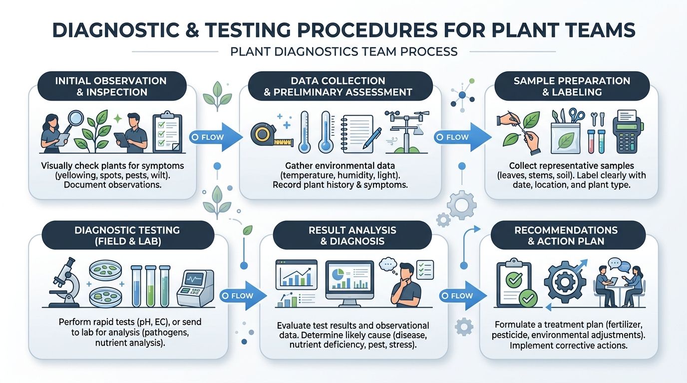
Diagnostic and Testing Procedures for Plant Teams
Trusting a steam relief valve because it passed once isn't enough. Plant teams need a repeatable method for checking whether the valve is still aligned with set pressure, still sealing properly, and still behaving predictably under real operating conditions.
In-situ checks that catch problems early
Online testing is useful because it evaluates the valve in its installed environment. That matters when piping stress, backpressure, vibration, and process dynamics are part of the failure mechanism.
For steam boilers, safety relief valves must be set to release at an overpressure of no more than 3% to 5% above the MAWP, a stricter tolerance than the 10% often allowed in other industrial applications, as explained in this steam safety valve selection guidance. That tighter margin is why precision matters during field verification.
A solid in-situ routine usually includes:
- Safety preparation. Confirm isolation boundaries, discharge path awareness, personnel notification, and permit controls.
- Baseline condition capture. Record current operating pressure, service condition, temperature behavior, and recent process events.
- Acoustic assessment. Use structured listening and, where available, dedicated ultrasonic leak detection to distinguish true leakage from ambient steam noise.
- Thermal scan. Temperature differences across inlet and outlet can reveal passing, near-lift behavior, or continuous leakage.
- Lift verification support. Where procedures and hardware allow, controlled assist or monitored pressure increase can confirm opening behavior without a blind trial.
Field note: Acoustic trending is most useful when the team records the same valve in the same operating state over time. One sound file alone rarely settles the diagnosis.
Bench testing and documentation discipline
Bench testing answers a different question. It removes process variables and checks the valve itself. During bench testing, teams verify set pressure, seat tightness, mechanical movement, and reseating behavior under controlled conditions.
For a high-pressure boiler in a manufacturing plant, the bench process should be disciplined enough to survive an audit and practical enough to support maintenance decisions. The records matter as much as the result.
A useful documentation format captures:
| What to record | Why it matters |
|---|---|
| Valve tag and service location | Prevents mix-ups and preserves history |
| Set pressure found | Shows drift from intended condition |
| Reseating behavior | Helps identify blowdown or stability concerns |
| Visible seat or nozzle condition | Distinguishes contamination from damage |
| As-found seal status | Flags unauthorized adjustment risk |
| Return-to-service date | Supports next maintenance planning |
Plant teams should separate two decisions that often get blended together. First, did the valve pass the test? Second, is the system around the valve causing premature wear? A valve can pass on the bench and still fail in operation because the installed condition is poor.
For teams that need a simple reference for operator-level awareness, a basic consumer-facing guide on how to check your relief valve can be useful as a reminder that even simple relief devices require routine verification. Industrial steam service, of course, demands a much stricter procedure, controlled conditions, and full documentation.
Preventive Maintenance and Regulatory Compliance
Preventive maintenance on a steam relief valve isn't just cleaning, tagging, and hoping the next test goes well. It is a controlled program tied directly to code requirements, equipment history, and actual failure behavior.
What plant teams should inspect routinely
Routine work should focus on condition, not just calendar intervals. In an oil and gas facility, for example, discharge piping exposure, corrosion risk, and process contamination can all shorten useful valve life even when the valve appears untouched from the outside.
A strong routine includes:
- Visual condition checks. Look for corrosion, damaged discharge routing, missing caps, and evidence of steam passing.
- Seal verification. Confirm tamperproof seals are intact and documented.
- Installation review. Check that the valve remains upright and that outlet conditions haven't been altered by later piping work.
- History review. Repeated seat work, repeated reset drift, or repeated near-lift events should trigger engineering review instead of another like-for-like repair.
For organizations balancing routine inspections against deeper condition monitoring, the decision isn't really preventive versus predictive. The best programs combine both, as discussed in this guide to predictive vs preventive maintenance.
Why compliance failures become reliability failures
For ASME Section I steam boilers, the valve must have capacity exceeding the boiler's maximum steam output, must have a tamperproof seal, and must be installed vertically under the ASME BPVC and National Board framework, as detailed in the Section I boiler relief valve requirements. Those aren't paperwork details. They directly affect whether the valve can open, discharge, and reseat safely.
Plants get into trouble when compliance is treated as a documentation exercise instead of a physical condition standard. A missing seal may indicate unauthorized adjustment. A non-vertical installation may affect movement. An undersized or modified discharge path can create backpressure that prevents proper lift.
In practical terms, every valve should have a traceable identity and service history that answers four questions quickly:
- Where is it installed
- What is it protecting
- What condition was it found in last time
- What changed since then
If a facility can't answer those questions, it doesn't have a valve program. It has a parts list.
Transform Valve Management from a Cost to a Strategy
A steam relief valve isn't a fit-and-forget component. It's a dynamic protective device that reflects the health of the steam system around it. When plants select the right design, install it correctly, monitor for instability, and test it with discipline, the valve becomes an early warning point instead of a recurring surprise.
That shift matters. It reduces repeat failures, strengthens compliance, and gives operations leaders a clearer view of process risk. More importantly, it changes valve management from reactive replacement to deliberate control of one of the plant's most critical safeguards.
Plants that treat relief valves as isolated hardware usually keep paying for the same failures. Plants that manage them as a system make better decisions on design, maintenance, and uptime.
If a facility wants a clear picture of where its steam relief valve program is vulnerable, Forge Reliability offers a free reliability assessment that reviews failure patterns, testing practices, installation risks, and predictive maintenance opportunities across critical steam assets.