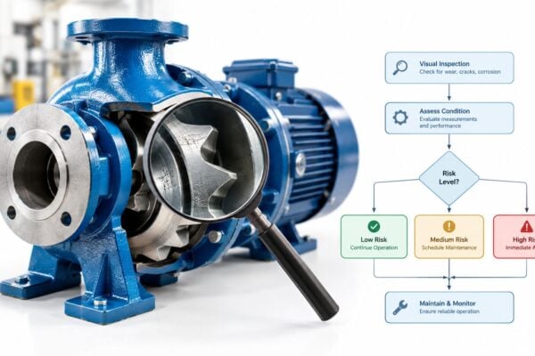
A pump-down check can go wrong before anyone touches the pump. A technician sees a vacuum gauge stall, hears the team call it a seal failure, and starts planning an overhaul. Yet the number may reflect the sensor's measurement principle, a contaminated filament, a controller offset, or electrical noise rather than the chamber condition.
Learning how to read a vacuum pressure gauge means more than following the pointer toward “vacuum.” The reading must be tied to its unit, reference point, gauge technology, valid pressure range, and recent maintenance history. That combination tells a reliability team whether to inspect the pump, investigate a leak, clean or recalibrate the sensor, or check the signal wiring.
Table of Contents
- When a Vacuum Gauge Reading Misleads the Whole Troubleshooting Effort
- Matching the Gauge Technology to the Pressure Regime
- Converting Between Torr, Inches of Mercury, Millibar, and Microns
- Failure Modes That Produce Bad Vacuum Readings
- Verifying a Gauge Reading Before You Act on It
- Acceptable Ranges and Maintenance Actions by Application
- Turning Reliable Vacuum Readings into Better Uptime Decisions
When a Vacuum Gauge Reading Misleads the Whole Troubleshooting Effort
A hot-oil system returned from overhaul with a Pirani gauge showing 8 mbar. The maintenance team treated that reading as evidence of a vacuum-pump seal problem and prepared for mechanical work. Before opening the pump, they should have asked whether the instrument still represented chamber pressure.
The pump eventually reached 50 microns overnight. The seals were not the root cause. Oil backstreaming had contaminated the sensor filament, a controller swap had introduced zero drift, and the system had been vented while the cathode was still hot. Room air crossing the hot sensing element produced another misleading response. The pump could create the required vacuum, but the displayed value redirected troubleshooting toward the wrong failure mode.
Practical rule: A bad vacuum number is not yet a pump diagnosis.
Start with the physical instrument. On an analog gauge, identify the active scale and unit, count the value of each minor tick, and place your eye perpendicular to the dial to avoid parallax. Confirm whether the mechanism uses a Bourdon tube, capsule element, or another dial-and-pointer design. A Bourdon tube converts pressure into mechanical movement. A capsule element responds to pressure changes through deformation. Either mechanism can indicate a number without proving that the connected process is healthy.
The history of vacuum conventions predates the electronic gauges installed on modern plant equipment. Torricelli's mercury tube, demonstrated in 1644, is regarded as the first documented pressure gauge and remained a foundation for vacuum measurement for roughly 350 years, from 1644 to about 1900 (historical background on pressure measurement). That history explains why equipment may display Torr, inHg, mbar, or kPa. Unit differences become a troubleshooting risk when operators record the number but omit the reference.
Read the reference before reading the number
Vacuum service usually involves absolute pressure, measured relative to a perfect vacuum. Gauge pressure measures the difference from local atmospheric pressure. As a result, a vacuum instrument may use atmospheric pressure as its zero-vacuum reference, while increasing vacuum moves the indication opposite to an ordinary pressure reading.
A lower absolute-pressure number means a harder vacuum. The same condition may appear as a large inHg vacuum indication, a low kPa absolute value, or a small micron value, depending on the instrument. Digital displays add their own traps. Verify the unit in the display header, determine whether the range is autoranging or fixed, and record the resolution represented by the least-significant digit.
The atmospheric reference is 760 Torr, 760 mmHg, or 29.92 inHg absolute, consistent with the historical conventions described in the pressure measurement reference. A maintenance log that records “8” without identifying mbar, Torr, or inHg cannot support a reliable diagnosis.
Record the number, unit, gauge type, operating condition, and time together. Compare that record with pump-down behavior, valve position, process temperature, and recent sensor or controller work. A stable reading after maintenance may indicate offset or grounding trouble rather than a process leak. A reading that changes with gas composition or contamination points toward sensor limitations. A reading that disagrees with an independent instrument supports a measurement fault before pump disassembly.
Use the same evidence-based discipline applied in compressor troubleshooting practices, where pressure signals are compared with temperature, current, vibration, and process load.

Matching the Gauge Technology to the Pressure Regime
A gauge can report a bad number while the pump, chamber, and valves are working correctly. Start by matching the sensing principle to the pressure range and gas being measured. Thermal-conductivity gauges infer pressure from heat transfer through the gas. Capacitance diaphragm gauges measure mechanical deflection. Ionization gauges use charged-particle behavior at very low pressure.
The technology changes the failure diagnosis. A Pirani gauge can respond quickly across a broad range, but gas composition and filament contamination can shift its indication. A capacitance diaphragm gauge is less affected when gas composition changes because it measures pressure directly. Ionization gauges suit much lower pressures, yet sudden venting, contamination, or operation outside the valid range can make their readings unstable.
| Gauge Type | Effective Range | Gas Composition Dependency | Typical Failure Regime |
|---|---|---|---|
| Pirani | Rough to high vacuum, with practical limits set by calibration and contamination | High, because thermal conductivity changes with gas and vapor | Contaminated filament, gas-composition change, low-pressure drift |
| Capacitance manometer | Pressure measurement across the calibrated full-scale range, including very low pressure applications | Low, because diaphragm deflection measures pressure directly | Reference drift after thermal cycling, overload, calibration shift |
| Thermocouple gauge | Rough and medium vacuum service | Significant, because heat transfer changes with gas | Slow response, limited range, filament or thermocouple failure |
| Ionization gauge | High and ultrahigh vacuum service | Gas dependent, with sensitivity affected by gas species | Sudden venting, contamination, unstable emission, operation outside valid range |
Use the gauge's calibration range as a diagnosis boundary, not just a purchasing detail. A High Vacuum Standard down to 10^-7 Pa, or 10^-9 Torr, and a Transition Range Vacuum Standard around 10^-2 Pa, or 10^-4 Torr, illustrate how sharply instrument suitability changes across the pressure regime. Recommended practice assigns capacitance diaphragm gauges above 10^-2 Pa, spinning rotor gauges from 10^-1 to 10^-4 Pa, and ionization gauges below 10^-4 Pa. Keep a calibration-range reference for vacuum instruments with the instrument record, then verify that the installed gauge is operating within its calibrated range.
Cryogenic service adds temperature, materials, and mounting constraints. Guidance on pressure gauges for cryogenic systems helps define those requirements before a low-temperature reading is compared with a room-temperature process reading. Apply the same sensor-selection discipline used in industrial compressor maintenance planning. If the number changes with gas composition, suspect the sensing method. If it remains fixed after sensor or controller work, inspect calibration, wiring, shielding, and grounding before opening the pump.
Converting Between Torr, Inches of Mercury, Millibar, and Microns
Start every conversion by identifying the pressure reference. 760 Torr equals 1 atmosphere, corresponding to 29.92 inHg absolute. That same reference is 101.4 kPa absolute, or 1013.25 mbar and 101325 Pa under standard atmospheric conditions.
A Torr is defined as 1 mmHg, and 1 Torr equals 133.322 Pa. These relationships follow established pressure measurement conventions. Before calculating, confirm whether the display reports absolute pressure or vacuum gauge pressure. Confusing the two can make a healthy pump appear to miss its target.
Use these working conversions:
- Torr to millibar: multiply Torr by 1.333.
- Torr to microns: multiply Torr by 1000.
- Microns to pascals: multiply microns by 0.1333.
- InHg to millibar: multiply inHg by 33.864.
For example, 50 microns equals 0.05 Torr, approximately 0.0667 mbar or 6.67 Pa. Those values describe absolute pressure when the instrument is configured for absolute measurement. An inches-of-mercury vacuum reading may instead show the difference from atmospheric pressure, so convert only after confirming the reference.
Use inHg or mbar for rough-vacuum work, where readings remain close to atmospheric pressure. Use microns, Torr, or Pa for high-vacuum work, where small absolute-pressure changes can distinguish a process restriction from a pump, leak, or instrument problem.
Failure Modes That Produce Bad Vacuum Readings
During a pump-down check, a bad number can send the team toward the wrong repair. Separate three possibilities first: the sensor is contaminated or out of range, the chamber has a process problem, or maintenance has introduced an electrical or connection fault.
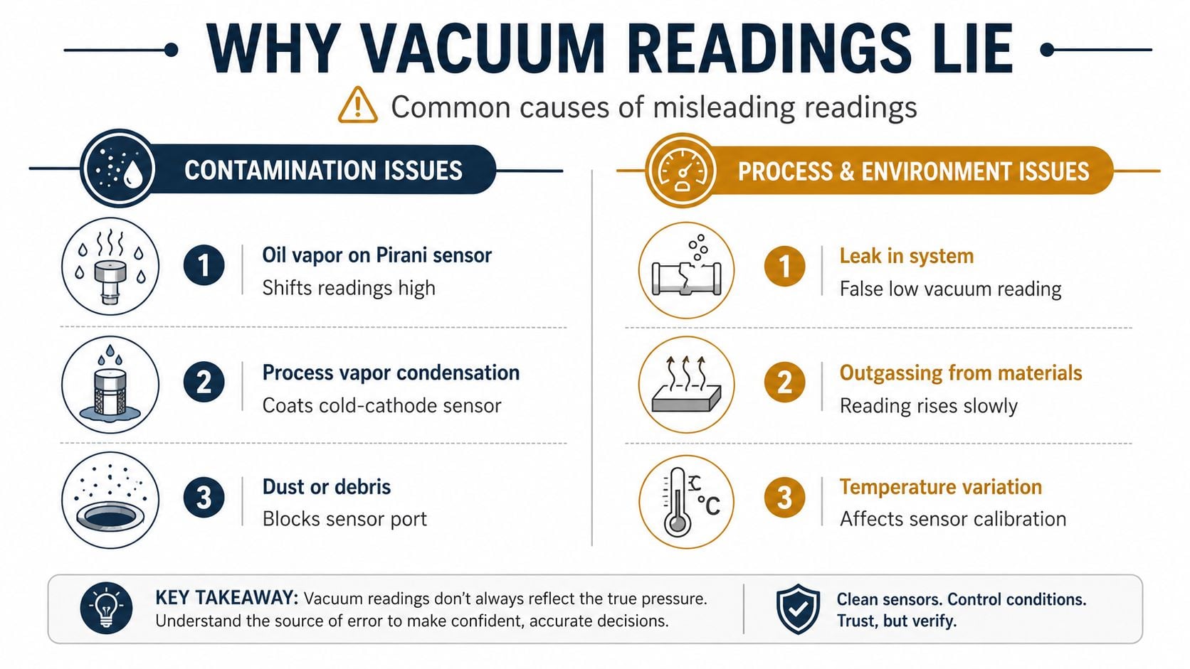
A Pirani sensor exposed to oil vapor can develop a film on its filament. Since it infers pressure from heat transfer, that film changes the thermal response and may drive the indication high. Process vapors can condense in a cold-cathode sensor, causing premature ignition or unstable operation. Dust or debris in the sensor port restricts flow, slows response, and makes the gauge appear to trail the chamber.
A credible reading can still support the wrong diagnosis:
- Leakage at a flange or fitting produces a higher pressure, or lower vacuum, than expected.
- Outgassing from materials or residue causes pressure to rise slowly after pump-down.
- Temperature variation changes sensor behavior and may shift calibration.
- Condensable vapor can resemble a pump or seal problem while the chamber continues releasing process material.
Electrical and post-maintenance causes
Ground loops between a controller and transducer can add an offset. Variable-frequency drives can couple electromagnetic interference into unshielded or poorly routed signal cables. Moisture in a connector can create intermittent behavior that looks like pressure instability.
After maintenance, compare the reading at atmosphere and at known reference points. Check cable condition, shielding, and termination, then compare the installed gauge with a calibrated gauge on the same chamber. General troubleshooting guidance for inconsistent vacuum readings supports this sequence. A disagreement between analog and digital outputs can point to EMI coupling rather than an actual pressure change.
One common pattern is a gauge that reads correctly at atmosphere but drifts after pump-down. Inspect the O-ring and fitting, confirm the torque, and look for a small leak that appears only under vacuum. Passing a static zero check does not clear the sensor for service.
For suspected flange and connection problems, supplement pressure observation with ultrasonic leak detection. It does not replace a valid reference gauge, but it can help distinguish a leaking connection from a failing pump.
Verifying a Gauge Reading Before You Act on It
A pump-down stalls below its normal endpoint. Before ordering seals, replacing the pump, or rejecting a process batch, verify the measurement. Use the same sequence each time so another technician can repeat the check and reach the same decision.
Confirm the gauge technology and range. A Pirani becomes questionable below its validated low-pressure range, while an ionization gauge is unsuitable for rough vacuum. Refer back to the calibration-range discussion in section 2 when checking whether the sensing principle fits the pressure regime. A bad number may reflect sensor limitation, not equipment failure.
Inspect the sensor and port. Look for oil film, condensation, debris, damaged seals, and signs of recent cleaning. A clean exterior does not prove the sensing element is clean. Contamination can shift the reading or slow its response.
Perform a connection leak check. Isolate the chamber where safe, monitor pressure rise, and inspect the gauge fitting with an approved method. Isopropyl alcohol spray or a helium sniffer may be used under site procedures, but interpret the response carefully because the test can disturb pressure or temperature.
Compare with an independent reference. Install a calibrated gauge using a different sensing principle at the same chamber port, or at a location with negligible pressure drop. If the readings disagree, resolve the instrument difference before condemning the pump. A stable process reading with a drifting reference gauge points toward instrumentation. A matching rise on both gauges points toward the chamber, connection, or pump.
Vent and verify the reference condition. Bring the sensor to atmosphere according to the manufacturer's procedure and confirm the expected atmospheric or zero indication. A gauge that fails this check has a reference or calibration problem, even if it appeared reasonable during pump-down.
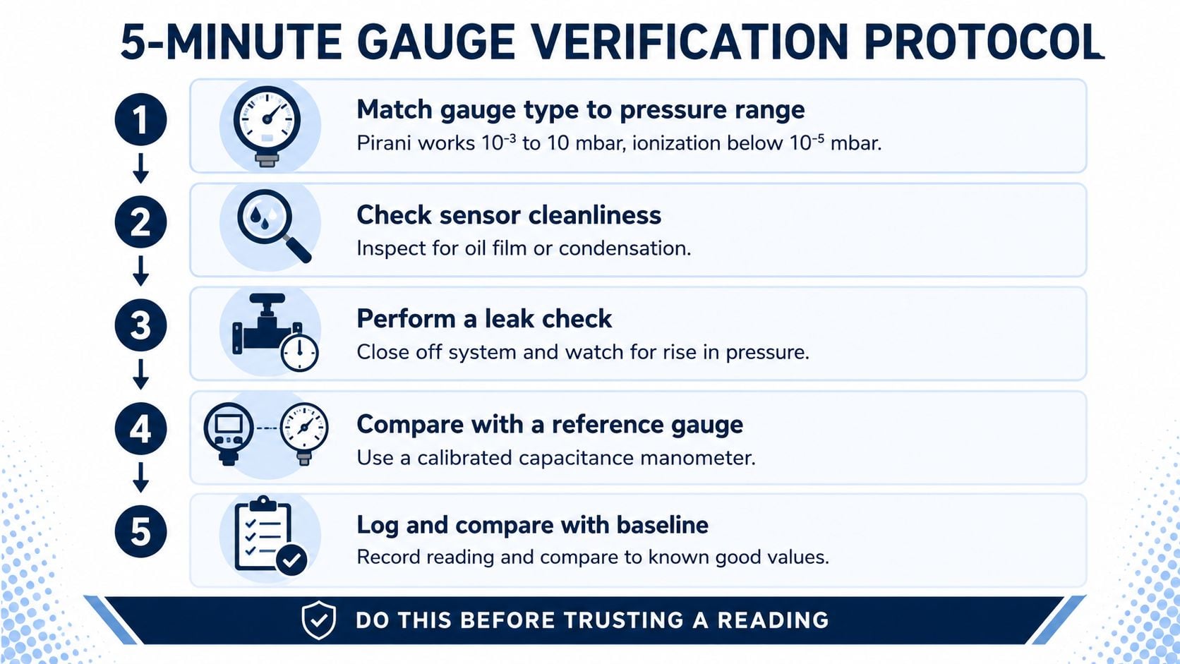
Record the calibration date, last verification, units, gauge location, and process condition. Retain analog and digital signals separately when possible. That history supports condition monitoring services by showing whether pressure drift follows equipment loading or appears immediately after instrumentation work. A disagreement that starts after maintenance warrants checks of grounding, shielding, cable routing, and terminations before pump repairs begin.
Acceptable Ranges and Maintenance Actions by Application
A vacuum reading is acceptable only when it suits both the process duty and the gauge technology. A value suitable for roughing may fail a sealed-chamber requirement, while a stable Pirani indication can become unreliable as pressure falls.
Use the table as an application guide, not a universal pass or fail limit. Each plant should set its baseline from equipment specifications, process qualification, and a verified reference instrument. For unit definitions and related calibration considerations, see the industrial vacuum unit conversion reference.
| Application | Acceptable Range | Recommended Gauge | Action if Out of Range |
|---|---|---|---|
| Rotary vane pump roughing | 50 to 100 mTorr ultimate | Pirani or suitable rough-vacuum gauge | Check pump oil, inspect hoses and fittings, then compare with a second gauge |
| Sealed process chamber holding vacuum | Single-digit microns stable | Capacitance manometer or validated high-vacuum gauge | Leak-check flanges, inspect O-rings, and review outgassing or contamination |
| HVAC dehydration | 500 to 1000 microns | Micron-capable vacuum gauge | Check hoses, core tools, valve seats, and the moisture-removal procedure before condemning the pump |
| Freeze-drying shelf pressure | 100 to 300 microns | Gauge validated for the shelf-pressure regime | Inspect chamber seals, condenser condition, product load, and sensor agreement |
The first maintenance decision is whether the reading remains inside the gauge's credible range. A Pirani value near its lower limit requires comparison with a capacitance manometer before it is used as a final process measurement. A stable chamber value does not clear the instrument, particularly after contamination or service work.
Read the drift pattern
A sudden step change after controller replacement points to configuration, wiring, or zero-reference problems. A gradual rise during isolation points more toward leakage, outgassing, or trapped moisture. A reading that changes with drive speed or nearby electrical equipment calls for checks of shielding, grounding, and cable routing before pump replacement.
For the rotary vane pump example, high ultimate pressure warrants oil inspection followed by a leak check. If both a reference gauge and the installed gauge show the same deterioration, investigate the chamber, connections, or pump. If only the installed signal moves, resolve the measurement fault first.
For freeze-drying, a shelf-pressure deviation merits a two-gauge comparison. Product vapor, condenser loading, and sensor behavior can each shift the displayed value, so replacing the pump based on one indication can extend the outage rather than correct it. Calibration-range guidance in the gauge-technology section above should be used when selecting the comparison instrument.
Turning Reliable Vacuum Readings into Better Uptime Decisions
A vacuum gauge is a diagnostic instrument, not merely a process indicator. The useful question isn't “what number is on the display?” It is “does this number agree with the gauge technology, reference condition, pump behavior, and process state?”
After every preventive-maintenance event, capture a baseline under known conditions. Record the gauge unit, sensor type, pump status, chamber condition, and time to reach the established pressure. A later trend becomes meaningful only when the measurement setup remains comparable.
Cross-reference pressure with other signatures from the same asset:
- Vibration can reveal bearing, coupling, or rotor problems that pressure alone can't identify.
- Motor current can show loading changes during evacuation.
- Temperature can expose oil degradation, cooling problems, or thermal effects on the sensor.
- Pressure-rise behavior can distinguish a leak or outgassing problem from a pump that never achieved capacity.
A practical worksheet should capture the baseline, two-gauge verification result, post-maintenance condition, calibration status, and monthly trend. That gives a technician a repeatable floor-level method instead of relying on memory or a single questionable display. Broader condition monitoring systems can then place vacuum behavior beside vibration, temperature, and electrical data in the same reliability decision.
The strongest programs also treat instrumentation work as a controlled maintenance activity. Sensor replacement, controller changes, cable rerouting, cleaning, and venting procedures should each trigger a verification record. That discipline prevents a small measurement error from becoming a seal replacement, pump swap, or emergency shutdown.
Forge Reliability provides predictive maintenance, condition monitoring, and reliability consulting for industrial teams that need trustworthy equipment data, including vacuum and rotating-asset diagnostics. Visit Forge Reliability to request a free reliability assessment and review gauge verification, baseline trending, and failure-mode priorities with its reliability engineers.