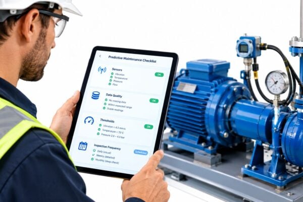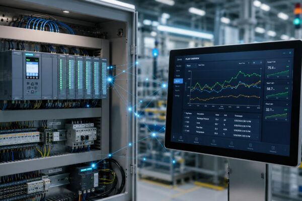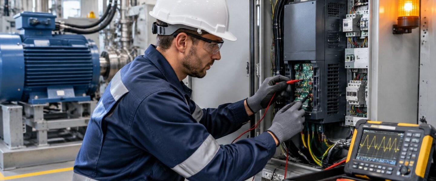
The drive trips during a production run, the operator resets it, and the same fault returns when the motor starts under load. Replacing the VFD may seem like the quickest fix, but the fault can live in the incoming supply, output cable, motor, driven equipment, settings, or plant environment. A drive reports what it detected. It doesn't automatically identify the root cause.
The reliable approach is to treat the drive, cable, and motor as one electrical system and isolate each part before condemning hardware. That starts with recording when the fault occurred and testing the conditions that can make a healthy drive trip.
Table of Contents
- Match the Fault to Its Likely Cause
- How to Isolate an Output-Side Ground Fault
- Power-Side Faults From Imbalance, Sags and DC-Bus Trips
- Motor-Side Damage From Reflected Waves and Bearing Currents
- Overheating and Contamination Failures in Harsh Plants
- EMC Noise and Parameter or Communication Faults
- Repair, Retrofit or Replace the Drive
Match the Fault to Its Likely Cause
A trip is a symptom, not a diagnosis. Before anyone resets the drive or changes parameters, record the exact fault code, when it happened, the load at the time, and any recent change, such as a new cable, motor, parameter edit, or firmware update. That short record often tells the crew which part of the system to check first.
Use the fault timing to guide the first test. A trip during acceleration points to different possibilities than one during deceleration, steady operation, or startup. The table maps common displays to likely cause families and the next place to investigate.
| Symptom | Likely cause family | First check | Go to section |
|---|---|---|---|
| Overcurrent trip during acceleration | Ramp too fast, mechanical binding, or output short | Acceleration ramp, free-spin the load, output-to-ground test | How to Isolate an Output-Side Ground Fault |
| Overvoltage trip during deceleration | Regeneration into the DC bus | Deceleration ramp, braking resistor, contactor timing | Power-Side Faults From Imbalance, Sags and DC-Bus Trips |
| Undervoltage or DC-bus undervoltage trip | Supply sag or loose input termination | Input voltage under load, all three phases | Power-Side Faults From Imbalance, Sags and DC-Bus Trips |
| Overtemperature trip or fan alarm | Clogged filter, failed fan, or blocked heat sink | Cabinet temperature trend and fan operation | Overheating and Contamination Failures in Harsh Plants |
| Output ground fault | Motor cable, motor, or filter insulation | Disconnect motor leads, then measure DC bus to each phase | How to Isolate an Output-Side Ground Fault |
| Bearing noise or repeated bearing failure | Common-mode shaft current and fluting | Shaft-to-frame voltage and bearing inspection | Motor-Side Damage From Reflected Waves and Bearing Currents |
| Random resets or nuisance trips | EMC noise, grounding, or shield termination | Shield path and cable separation | EMC Noise and Parameter or Communication Faults |
| Comms loss or parameter mismatch | Settings changed after firmware update or drive swap | Compare parameter file to backup, network termination | EMC Noise and Parameter or Communication Faults |
Practical rule: If a fault appears only under load, or only when the motor is connected, the drive itself is rarely the first place to look.
The table is a triage tool, not permission to test energized equipment without the right training and controls. Follow site lockout/tagout procedures, account for stored energy in the DC bus, and use the manufacturer's approved method for any energized measurement. A fault history paired with operating conditions can prevent unnecessary resets and component swaps by preserving evidence before it disappears.
How to Isolate an Output-Side Ground Fault
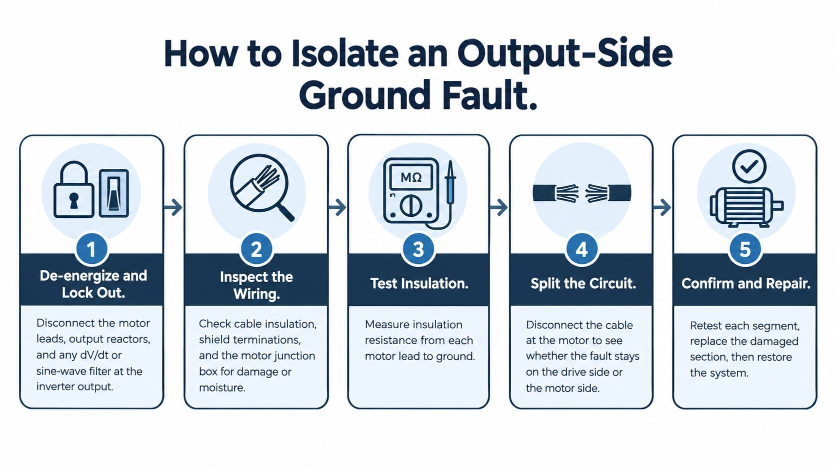
A ground-fault trip does not automatically mean the inverter has failed. A damaged cable, wet motor junction box, contaminated filter, or winding insulation breakdown can create the same symptom. Test the drive, cable, and motor as one electrical system, separating each part before ordering a replacement. Isolate the motor circuit first, then check the inverter independently.
De-energize and isolate. Apply lockout/tagout, verify absence of voltage, and wait for the DC bus to discharge according to the manufacturer's instructions. Disconnect the motor leads, output reactors, and any dV/dt or sine-wave filter at the inverter output. This keeps downstream equipment out of the initial drive checks.
Inspect the circuit. Check cable insulation, shield terminations, conduit, motor terminals, and the junction box. Look for cuts, loose connections, moisture, corrosion, or contamination that could provide a path to ground.
Test the motor and cable separately. With the VFD fully disconnected, use an insulation resistance tester on the motor and cable. Record the readings and compare them with the motor nameplate guidance or a previous baseline. Never megger connected VFD electronics, since the test voltage can damage input or output semiconductor devices. Follow an insulation resistance testing procedure suitable for the motor and cable.
Check the disconnected inverter output. Keep the motor circuit disconnected and measure DC voltage from the negative DC bus to U, V, and W. In this check, readings are expected to be approximately 5–50 VDC. A reading of 0 VDC or approximately full DC-bus voltage points to a likely failed inverter power section. Confirm the test method against the drive manufacturer's manual.
Check phase readings near zero hertz. Command operation near 0 Hz and measure from both positive and negative DC bus rails to each output phase. Readings should be approximately 50% of the full DC-bus voltage. Use the manufacturer-approved method and a properly rated instrument. An ordinary handheld meter may misread the rapidly switched PWM waveform.
Compare phase-to-phase voltage at full speed. Ramp the drive to full speed and compare U–V, V–W, and W–U using the specified procedure for the drive and instrument. Unequal readings point toward the drive or its switching section.
Reconnect and verify. Reconnect the motor circuit and run the equipment under controlled conditions. If the fault returns only after reconnection, investigate the cable, motor, filter, and installation before replacing the drive.
Follow the readings through to the physical fault. For example, if a fault clears with the motor disconnected and returns after a cable splice is reworked, the splice is the likely source, not the inverter. On a 75 kW cooling-water pump, identifying a damaged splice can keep the drive in service while the splice is repaired and retested.
Power-Side Faults From Imbalance, Sags and DC-Bus Trips
A 480 V manufacturing conveyor reads 480, 450 and 420 V phase to phase under load. The average is 450 V, and the greatest deviation is 30 V, or 6.7%. Treat that imbalance as a supply problem to investigate before condemning the drive. As a practitioner rule, imbalance above approximately 6–8% warrants investigation.
Measure all three line-to-line voltages while the equipment is operating. Calculate their average, then express the greatest deviation from that average as a percentage. If the result is high, inspect upstream fuses, disconnects, transformers and terminations. Compare phase currents too: current imbalance can point to a failing rectifier in the drive. A loose termination can cause nuisance trips even while the conveyor moves freely.
Capture readings when the process is demanding power. An idle measurement may miss a supply problem that appears only under load.
Supply sags and distorted waveforms
The DC bus is the drive's intermediate direct-current link between the input rectifier and inverter. A supply sag can keep it from charging adequately, particularly when a nearby large motor starts or a pump accelerates. The drive may trip on DC-bus undervoltage, sometimes followed by output-overcurrent behavior. Harmonics, or distortion in voltage or current waveforms, can increase current draw and heating without appearing in a static voltage check.
Use a power-quality recorder to capture input phases, DC-bus behavior, current and harmonics during the trip. Inspect feeder impedance, transformer capacity and terminations, then assess whether harmonic mitigation is needed. A targeted electrical fault detection investigation can help separate a supply disturbance from a fault inside the drive.
Deceleration and bus overvoltage
Overvoltage during deceleration often means the motor is returning energy to the DC bus faster than the system can absorb it. A high-inertia centrifuge that trips at every stop may have a ramp-down setting that is too short. Record when the trip occurs, review the deceleration ramp, inspect the braking resistor and chopper if fitted, and confirm that a bypass contactor is not opening while the inverter is energized.
After corrective work, repeat the imbalance and sag measurements under load. Verify the result at the operating condition that produced the fault. This helps establish whether the supply, drive, or connected equipment is responsible before replacing components.
Motor-Side Damage From Reflected Waves and Bearing Currents
A cooling-tower fan bearing fails again soon after replacement. The alignment and lubrication checks look acceptable, and the motor runs from a VFD over a long cable. Before condemning the drive, test the motor, cable, and drive as one electrical system. Current through a bearing or reflected voltage at the motor can cause damage even when the drive itself is operating correctly.
The VFD switches its output using pulse-width modulation (PWM) to produce a variable-frequency waveform. Fast voltage rise times interacting with cable impedance can reflect pulses back toward the motor. Under some conditions, terminal peaks can approach twice the DC-bus voltage. A useful engineering example is a motor-terminal peak of approximately 1,500 V, which can stress winding insulation, especially at connection points.
PWM can also produce common-mode voltage, shared across the output phases relative to ground. Capacitance in the motor and cable can couple this voltage onto the shaft. If shaft voltage breaks through the bearing's lubricating film, electrical discharges pit the raceway and may leave evenly spaced fluting. Inspect the failed bearing: these marks can resemble ordinary wear, so treat them as a clue rather than proof.
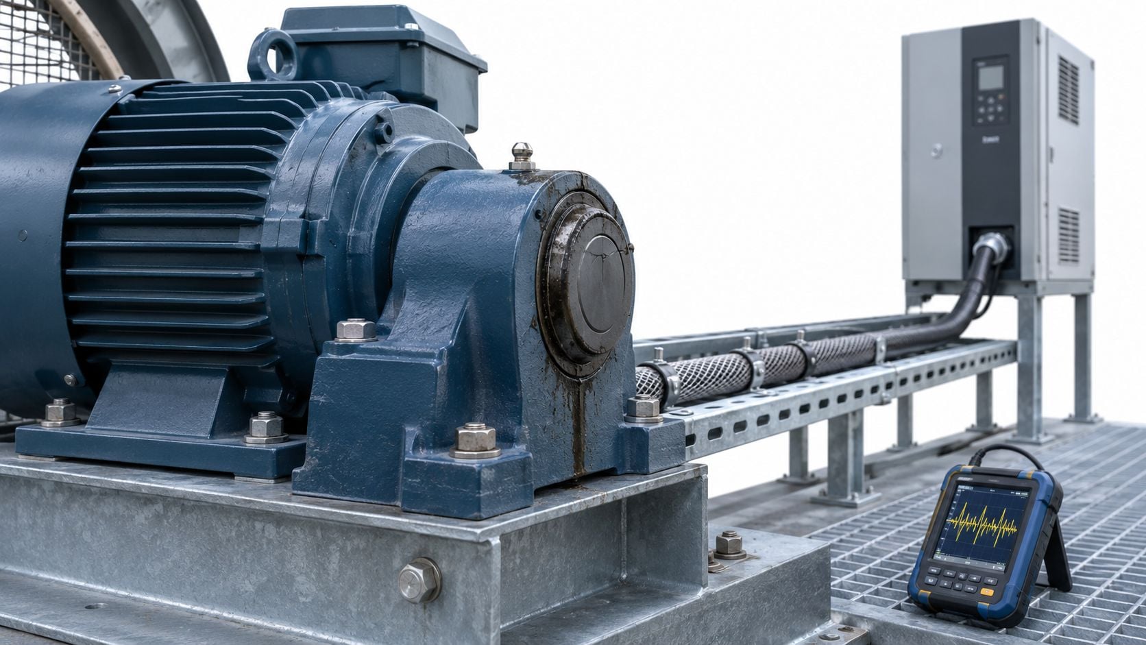
Diagnose the current path before choosing a fix
- Trend bearing vibration and ultrasonic activity against drive speed, switching frequency, and load. Changes that track operating conditions support an electrical contribution.
- Inspect the failed bearing for frosting or evenly spaced fluting. Record what you see, then verify the suspected current path.
- Measure shaft-to-frame voltage with a high-frequency-capable probe while the motor runs across its normal speed range.
- Check high-frequency bonding between the motor frame and drive, cable-shield termination, and the driven-equipment frame.
Combine insulation testing, motor-current signature analysis, vibration analysis, and oscilloscope checks of peak voltage and rise time. Test the installed cable and motor, not just the drive on the bench. The right remedy depends on the measured current path, cable installation, and motor construction.
| Option | What it addresses | Pitfall |
|---|---|---|
| Inverter-duty motor with reinforced insulation | Peak voltage at motor terminals | Does not by itself stop bearing currents |
| Output reactor or dV/dt filter | Reflected-wave peaks and voltage rise time | Adds voltage drop and heat; size it to the drive and cable length |
| Shaft-grounding ring | Common-mode shaft current through bearings | Needs a low-impedance bond to the motor frame |
| Insulated or hybrid bearing | Discharge through the bearing raceway | Without a current path, discharge can shift to the opposite bearing or coupled machine |
| Common-mode filter | High-frequency common-mode current | Requires correct installation and grounding |
| High-frequency bonding and cable-shield termination | Return-current paths at drive and motor ends | Can take significant retrofit labor; check both ends |
An insulated bearing alone may redirect discharge to the opposite bearing, gearbox, or coupled equipment. The mitigation has to divert or control current across every path. Use this guide to bearing failure mechanisms alongside the electrical measurements when investigating repeat failures.
Overheating and Contamination Failures in Harsh Plants
On a washdown bottling line, a drive cabinet sits close to hose spray and caustic mist. Moisture and chemical residue can degrade insulation and corrode connections. At the same time, clogged filters or restricted airflow trap heat inside the enclosure. Many VFD failures start with operating conditions that the electronics cannot tolerate. Replacing the drive without correcting those conditions risks repeating the failure.
Treat the drive, cable, motor, and enclosure as one operating system. Before condemning the drive, inspect for water ingress, residue, blocked air paths, and loose or corroded connections. A fault that appears to be a failed drive may instead point to heat or contamination affecting the installation.
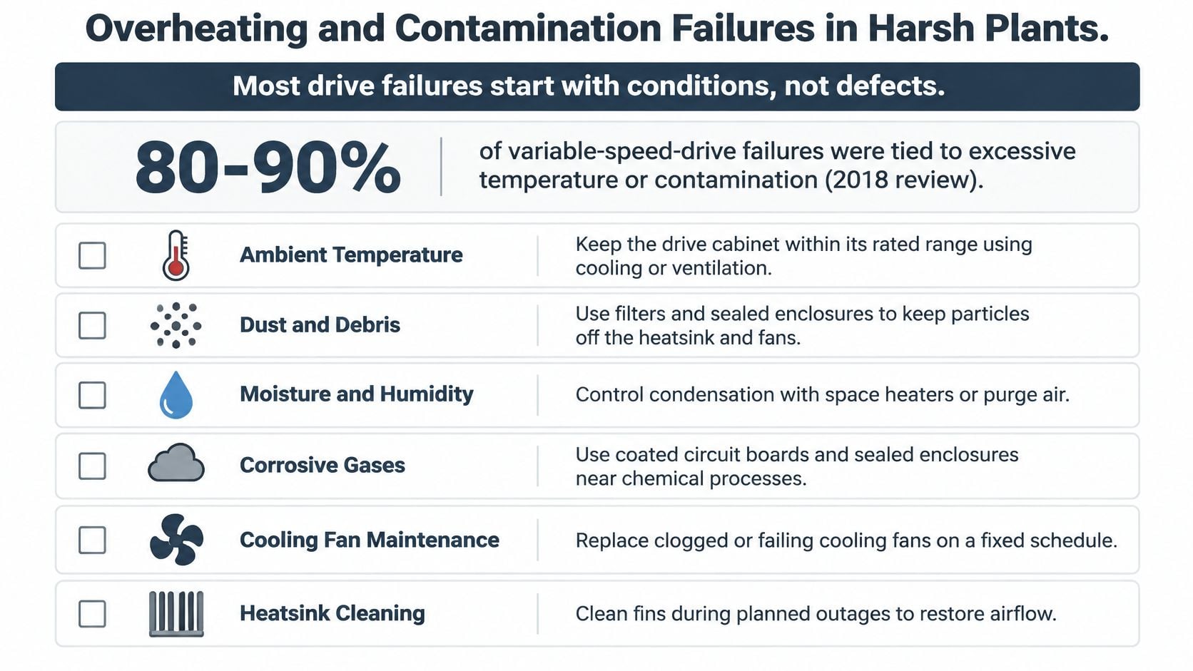
Use conditions to set the inspection routine
- Trend cabinet temperature. Compare readings with ambient temperature and set an alarm band suited to the installation.
- Check fans and airflow. Inspect cooling fans during scheduled drive checks, and confirm that air can move through the enclosure.
- Clean heat sinks carefully. Follow the drive manufacturer's approved method to avoid damaging fins or spreading contamination.
- Maintain filters by condition. Use pressure drop or visible loading to guide replacement, rather than relying on calendar timing alone.
- Keep ventilation paths open. Check that stored materials, added cable, or nearby equipment have not blocked clearances or cooling paths.
- Review event history. Compare overtemperature trips, DC-bus events, and recurring resets with cabinet and ambient temperature trends.
For dusty or washdown areas, begin with monthly inspections and adjust the interval based on observed conditions. Critical drives may warrant continuous temperature and power-quality monitoring. Compare affected cabinets with others on the line: if temperatures rise across the area, investigate the room or cooling system before replacing individual drives. Under load, thermography inspections can reveal heat patterns that merit closer checks of electrical connections or cooling performance.
EMC Noise and Parameter or Communication Faults
Keep power and control cables physically separated. Where they must cross, route them at right angles. Terminate cable shields 360 degrees at the drive end, avoid long pigtails that weaken the shield's high-frequency path, and verify a low-impedance ground connection shared by the motor and drive.
On a packaging line, random drive resets appeared only when a welder in the next bay fired. The fix was to re-terminate the shield and reroute control wiring away from the noisy power path. That's a useful reminder: intermittent resets can follow switching activity elsewhere in the plant, even when the drive cabinet appears normal.
Verify settings after a drive change
After a drive swap or firmware update, compare the live parameter file with the last verified backup. Pay close attention to motor nameplate entries such as rated current, poles, and frequency. Incorrect motor data can cause trips that resemble a mechanical overload, so record changes and confirm them against the actual motor.
Check the communication path
For a Modbus RS-485 network, confirm that termination resistors are installed at the two ends of the bus, typically 120 ohms, and that bias is set once. Match baud rate, parity, and address to the controller. Check the communication timeout as well: a short timeout can turn a brief network dropout into a drive trip.
For a networked line, confirm that the controller and supervisory system agree on device settings and expected responses. This overview of PLC and SCADA integration provides context for tracing drive communication faults through the control system.
Log each communications or EMC event with its time, load, and any nearby equipment that switched. Repeated timing patterns can reveal a noise source or a process condition that a single reset won't expose.
Repair, Retrofit or Replace the Drive
A replacement drive will not correct a fault in the cable, motor, or incoming supply. Treat the drive, cable, and motor as one electrical system. Before condemning the drive, confirm that the motor and cable pass appropriate insulation and continuity checks, and that supply conditions are acceptable. Then match the repair decision to the confirmed fault, the drive's service life, and the cost of downtime.
| Root cause | Decision | Action and check |
|---|---|---|
| Contained component failure within service life | Repair | Use a qualified repair service; confirm turnaround before committing |
| Supply imbalance or voltage sags | Retrofit | Correct terminations or the upstream supply; verify readings under load |
| Reflected-wave stress or bearing currents | Retrofit | Consider a reactor or dV/dt filter, shaft grounding, and bonding; recheck bearings |
| Poor shield path or EMC noise | Retrofit | Reroute cables or re-terminate shields; confirm bonding and monitor for repeat events |
| Repeated power-section failure, past service life, or no spares | Replace | Compare replacement cost with downtime cost per hour |
A worked cost comparison can clarify the trade-off: a 50 HP VFD replacement at $6,800 versus a repair at $2,450, a $4,350 difference. These reported costs are a comparison point, not a universal estimate, since prices vary by region and drive class (reported drive repair and replacement costs).
On a critical production line, purchase price is only part of the decision. Reported production downtime from a failed variable-speed drive can exceed £90,000 per hour (reported production downtime impact). Weigh that exposure against repair turnaround, spare availability, and the chance of another failure. A repair cannot fix a wet motor junction box or a damaged cable shield. A replacement can fail for the same reason if the installation stays unchanged.
Forge Reliability offers a free reliability assessment to review VFD trip history and prioritize checks across the drive, cable, motor, and supply. Share recurring faults and operating conditions, then visit Forge Reliability to arrange an assessment.