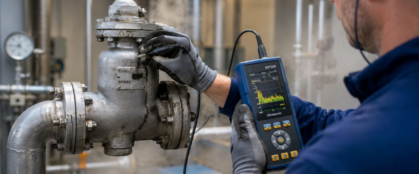
Steam systems rarely announce trouble in a way that shows up neatly on a KPI dashboard. They announce it on the plant floor. A maintenance manager sees flash steam where it shouldn't be. An operator reports uneven heating on a jacketed vessel. A planner notices that the same condensate return area keeps generating work orders. Meanwhile, energy spend stays stubbornly high and nobody can point to one obvious root cause.
That's where ultrasonic steam trap testing earns its keep. It isn't just a way to find failed traps. It's a way to separate noise from loss, identify the failure mode that matters, and turn steam system data into maintenance action that protects reliability, process stability, and operating margin.
Table of Contents
- Why Your Steam System Is Costing More Than You Think
- Inspection Prep and Instrument Setup
- The Three-Point Contact Measurement Technique
- Interpreting Ultrasonic Signatures and Thermal Data
- From Data Collection to Profitable Action
- Build Your Proactive Steam Management Program
Why Your Steam System Is Costing More Than You Think
What the plant floor is already telling you
A common plant scenario looks like this. A food processing site has a packaging line with intermittent heating problems, operators complain about wet steam symptoms at one point of use, and the condensate return area shows visible plumes during part of the shift. Nobody sees one catastrophic failure, so the steam system gets treated like background infrastructure instead of a profit leak.
That's a mistake.
The U.S. Department of Energy estimate summarized here states that 15% to 30% of steam traps in a system will fail within 3–5 years if they aren't regularly inspected and maintained, and facilities using proactive ultrasonic survey programs can reduce that failure rate to less than 5%. For a plant with a broad trap population across heat exchangers, tracing, unit heaters, and process vessels, that isn't a minor maintenance issue. It's an operating condition.
A failed-open trap wastes live steam. A blocked trap holds condensate in the process, which hurts heat transfer and can drive waterhammer risk. An intermittent or misread trap creates something just as damaging in practice. Confusion. The team starts replacing traps based on guesswork, and the same trouble spots keep coming back.
Practical rule: Steam trap work should start where energy loss, process instability, and equipment risk overlap. Not where the hiss is loudest.
A chemical plant steam skid makes this visible fast. One leaking trap on a high-demand jacketed reactor loop can keep the system running, but it can also push excess steam into the condensate side and mask other issues downstream. One blocked trap in the same area can create pooling condensate and unstable vessel temperature. The symptoms look different, but both failures drain money.
Why reactive trap maintenance keeps losing money
Reactive maintenance sounds efficient because the team only touches what appears broken. In steam systems, that logic usually fails because many bad traps don't advertise themselves clearly enough for a walk-by inspection. By the time the system shows obvious process impact, the plant has already paid for the wasted energy and absorbed the reliability risk.
That's why strong programs pair ultrasound with confirmation methods such as thermographic steam system inspections. Ultrasound hears internal flow behavior while the system stays online. Thermal checks help confirm whether a trap is discharging condensate or holding it.
A good survey changes the question from “Which traps are broken?” to “Which failures are hurting this plant the most right now?” That shift matters. It turns trap testing from a maintenance chore into a reliability and cost recovery activity.
Inspection Prep and Instrument Setup
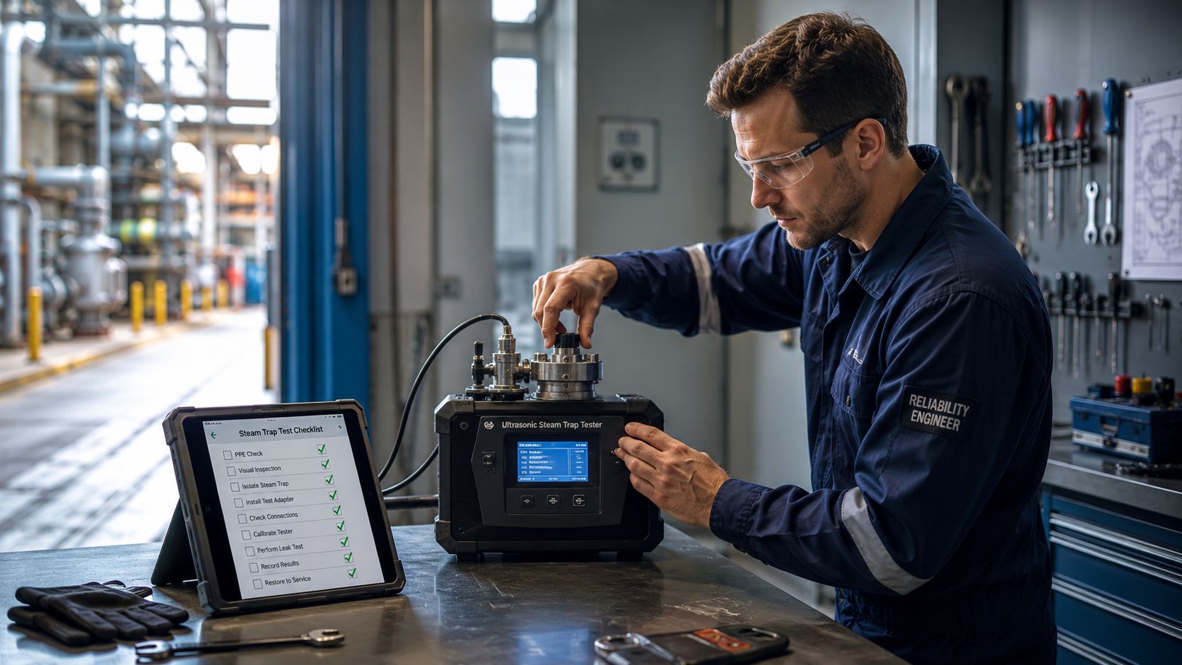
Build the survey kit before the route starts
Bad steam trap data usually starts before the first reading. The technician walks out with low batteries, no route sheet, the wrong sensitivity assumption, and no way to cross-check what the instrument is hearing. After that, every reading becomes harder to trust.
For a proper ultrasonic steam trap testing route, the field kit should cover both detection and verification:
- Ultrasonic instrument with contact probe: Steam trap diagnosis depends on structure-borne sound, not just airborne noise.
- Headphones: Background plant noise hides subtle changes in cycling and turbulence.
- Surface temperature tool: A spot check helps confirm blocked or cold conditions.
- Current route list or trap inventory: Missing trap identity breaks the value chain from inspection to work order.
- PPE for hot surfaces and active process areas: Gloves, eye protection, hearing protection, and plant-specific requirements are essential.
- Charged batteries and spare power: A route cut short by dead equipment creates partial data and repeat travel.
A pulp and paper mill is a good example of why setup matters. One route may move from lower pressure drying sections to higher pressure utility or process headers. If the technician treats those locations as acoustically identical, the data quality falls apart.
A survey route should be planned like any other reliability route. Asset ID, operating condition, access constraints, and expected failure mode should be known before the first probe touch.
Teams that want broader context around where ultrasound fits in PdM usually benefit from reviewing ultrasonic testing maintenance applications alongside steam-specific procedures. Steam trap testing is one application. The discipline behind route planning is the same.
Set sensitivity by pressure, not habit
One of the fastest ways to create false positives is using one standard sensitivity setting for every trap. The field result is familiar. Everything seems to hiss. Everything seems suspicious. Confidence in the program drops because the instrument is hearing too much unrelated noise.
According to this ultrasonic guidance on steam trap settings, sensitivity should be reduced as system pressure rises: 92% or higher for 0–20 psi, 80–85% for 20–150 psi, 74–78% for 150–300 psi, and 60–65% for 300–600 psi. If sensitivity isn't adjusted this way, background noise can create false-positive hissing readings.
That setting logic matters because higher pressure systems generate stronger turbulence and more competing ultrasound. The detector doesn't know what the technician intended to hear. It only reports signal. Setup determines whether that signal belongs to the trap under test.
A clean pre-survey checklist helps:
| Pre-survey item | Why it matters |
|---|---|
| Confirm trap operating pressure | Sensitivity depends on pressure range |
| Verify access to upstream and downstream points | Single-point testing weakens diagnosis |
| Check instrument response with probe attached | Poor probe contact invalidates readings |
| Review trap type and service | Cycling behavior varies by application |
| Prepare temperature confirmation method | Supports blocked or cold diagnoses |
The basic rule is simple. If setup is sloppy, the route produces noisy opinions instead of usable reliability data.
The Three-Point Contact Measurement Technique
A steam trap shouldn't be judged from one touch on the trap body. In crowded piping, that's how technicians end up reading surrounding turbulence, valve noise, or flash conditions instead of the trap itself.
The strongest field method is the comparison approach. A high-pressure trap on a food processing cooker line is a good example. Steam demand changes with production, nearby valves add noise, and the condensate side may carry sound that misleads a quick check. The three-point method gives the technician a baseline before making a call.
Where to place the probe and why it matters
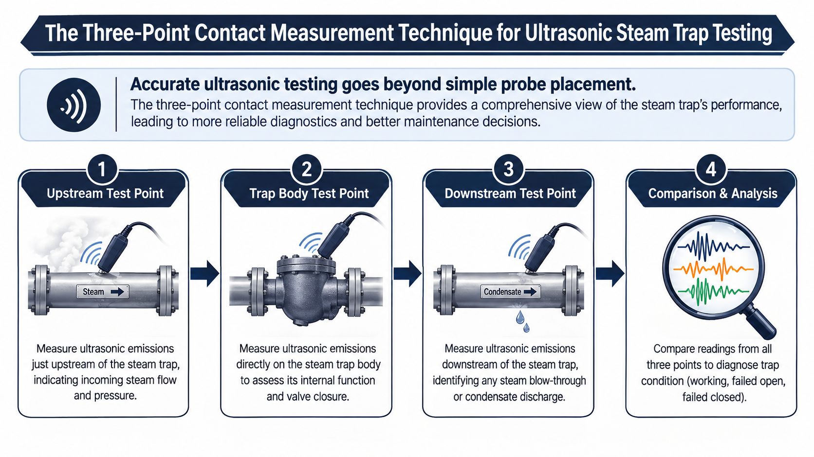
This training reference states that ultrasonic steam trap testing reaches approximately 98.5% accuracy when using the comparison method, which requires three benchmark readings: upstream at test point 1, at the discharge orifice at test point 2, and downstream at test point 3. It also specifies tuning the instrument to 25 kHz if adjustable, or 38 kHz if fixed.
The contact point at the discharge orifice is critical. That's where turbulence is most useful for establishing the trap's local acoustic baseline. Testing only on the body often blurs the signal with surrounding vibration and line noise.
A practical route looks like this:
- Upstream reading at test point 1: This captures incoming flow conditions and nearby acoustic environment.
- Discharge orifice reading at test point 2: This becomes the comparison baseline because turbulence is concentrated here during discharge.
- Downstream reading at test point 3: This reveals whether steam is carrying through when it shouldn't.
Probe contact has to be firm and repeatable. A glancing touch or painted, unstable contact point changes the reading enough to make trend data unreliable.
How to make the comparison call
The comparison method works because it filters competing ultrasound by asking a direct question. Is the downstream signal behaving like a normal discharge pattern, or is it stronger than the baseline in a way that suggests leakage?
The same training reference explains the decision rule this way: if test point 3 is equal to or less than 5–10% higher than test point 2, the trap is considered functional. If test point 3 exceeds 10% higher than the base point, the trap is leaking steam.
That's the diagnostic backbone. The field technique around it still matters:
- Wait for the trap to cycle: If the trap doesn't cycle during the observation window, a snap judgment can be wrong.
- Use pressure-appropriate sensitivity: A good comparison with a bad setting is still bad data.
- Record all three readings: The route report should show the logic, not only the conclusion.
- Note trap type and service: Continuous-flow behavior and cycling behavior aren't interpreted the same way.
Field note: If the technician can't explain why point 2 is the baseline and why point 3 determines leakage, the route is probably being run as a checkbox exercise.
A thermostatic trap on a chemical reactor jacket shows why this discipline matters. During normal operation, the trap may cycle in a way that sounds inconsistent to an untrained ear. The three-point method keeps the technician anchored to comparative evidence instead of gut feel.
Interpreting Ultrasonic Signatures and Thermal Data
The instrument display never tells the full story by itself. What matters is the pattern. A healthy trap, a leaking trap, and a blocked trap each leave a different acoustic and thermal fingerprint. The technician who listens only for “noise” will miss that. The technician who compares sound behavior with heat behavior will make far better calls.
What good, leaking, and blocked traps sound like
In a refinery steam skid or a dense utility rack, the first challenge is rarely hearing something. It's hearing the right thing. Guidance on competing ultrasound in dense steam skids notes that background noise can make single-point sensitivity settings inaccurate, and that the three-point comparison method is used to establish a baseline and filter this interference, though high-interference environments still require careful analysis.
The most useful field descriptions are plain ones:
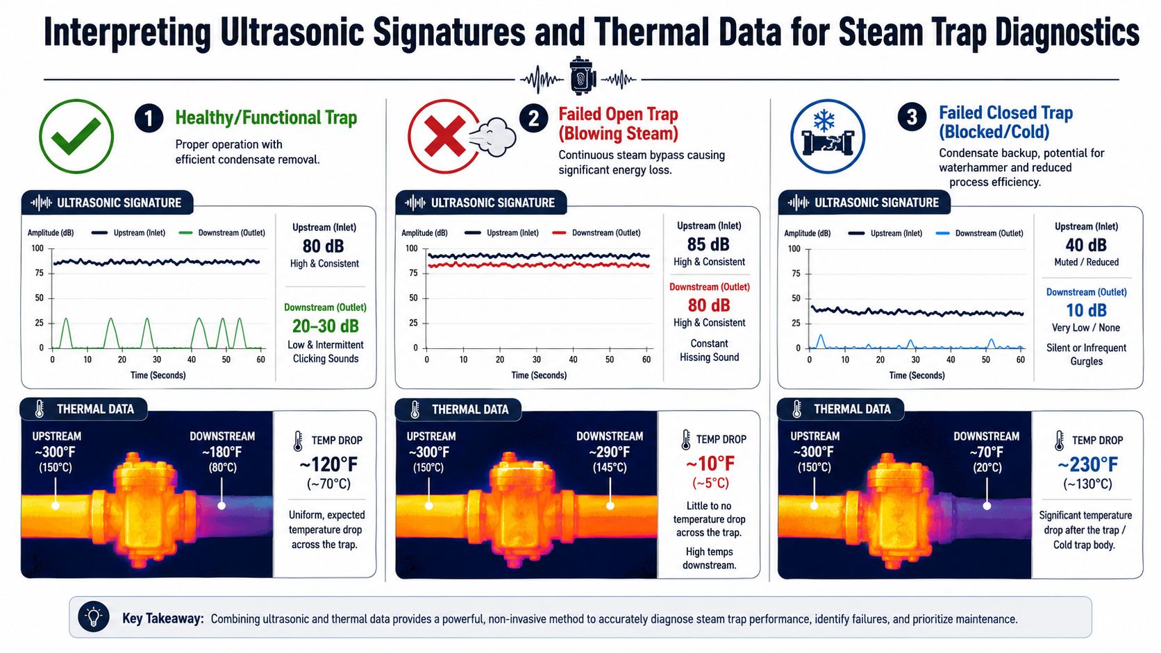
- Healthy cycling trap: Intermittent discharge sound. Short bursts, periodic rushing, or a repeating whoosh pattern depending on trap type and load.
- Failed-open or blow-through trap: Constant rushing or hissing. The sound doesn't relax between cycles because live steam keeps passing.
- Blocked or cold trap: Little sound, no clear discharge event, or muted irregular gurgling if condensate is stacked upstream.
A technician on a pharmaceutical jacketed vessel line might hear what sounds like steady activity and assume the trap is working hard. That can be exactly backward. A trap that never quiets down often deserves more scrutiny than one that cycles cleanly.
A quick interpretation table helps new team members:
| Observed pattern | Likely condition | Reliability concern |
|---|---|---|
| Intermittent discharge with clear cycling | Functional trap | Normal condensate removal |
| Constant high-level rushing | Leaking or blow-through | Energy waste and return system upset |
| Minimal sound with poor heating complaints | Blocked or non-cycling | Condensate backup and waterhammer risk |
When thermal data settles the argument
Ultrasound tells the flow story. Thermal data helps confirm whether the story makes process sense. That's especially helpful when a trap appears silent or when nearby noise makes the acoustic call less confident.
A blocked trap often shows itself through temperature behavior. If the upstream side remains hot while the downstream side drops off sharply, condensate may not be discharging as it should. If a trap appears to be blowing through, little thermal drop across the trap can support that conclusion.
Thermal confirmation shouldn't replace acoustic diagnosis. It should strengthen it when the failure mode affects temperature in a predictable way.
Teams often improve route quality by combining steam trap work with broader ultrasonic leak detection practices. The habit of comparing signal context, not just reading a number, applies across utilities.
Dense installations still demand caution. Competing ultrasound from valves, flash tanks, and adjacent piping can blur interpretation. In those areas, confidence comes from comparison logic, patient observation of cycling behavior, and thermal confirmation. Not from a single loud reading.
From Data Collection to Profitable Action
Most steam trap programs lose momentum after the survey. The route gets completed. A list of failed traps appears. Then the report sits in a folder because nobody has translated condition data into a repair sequence the plant can defend.
That's where many otherwise competent programs stall. The technical work gets done, but the business case never gets built.
Why pass fail reporting falls short

A pass/fail list is useful for maintenance history, but it's weak for decision-making. It treats all bad traps as equal. They aren't. A leaking trap on a critical high-pressure process service and a marginal trap on noncritical drip leg duty don't belong in the same repair priority merely because both were marked bad.
That weakness is a known industry gap. This discussion of steam trap testing limitations notes that most programs fail to quantify leakage rates from ultrasonic signatures to calculate energy waste and ROI, which leaves engineers unable to prioritize repairs based on financial impact and weakens the case for immediate repair over deferral.
That doesn't mean the route is useless. It means the route report needs more structure.
Data collection has value only when it changes the work order queue, the repair timing, or the capital discussion.
A practical report for a food and beverage plant or chemical unit should capture more than condition code:
- Asset identity and location: So the planner can find and schedule it.
- Failure mode: Leaking, blow-through, blocked, non-cycling, or uncertain pending confirmation.
- Service criticality: Process heating, tracing, utility support, freeze protection, or ancillary duty.
- Operational consequence: Energy loss, poor heat transfer, waterhammer exposure, or production instability.
- Recommended action: Repair, replace, inspect surrounding piping, or verify back-pressure issue.
For teams building stronger workflow logic between route data and maintenance planning, Wistec's predictive analytics solutions are a useful reference point for how industrial data can support prioritization and decision support rather than simple condition logging.
How to build a repair priority list that management will fund
The most useful steam trap priority list combines condition, consequence, and execution practicality. That's what gets funded.
One workable ranking model looks like this:
- Repair first the traps with confirmed steam leakage in critical service. These affect both energy use and process stability.
- Move blocked traps up the list where waterhammer, flooding, or product quality risk exists. The energy story may be less visible, but the equipment risk is often higher.
- Bundle work by area and outage window. The best repair list is one the planner can execute.
- Flag repeat offenders for engineering review. Repeated trap replacement in the same location often means the trap isn't the only problem.
A CMMS should reflect those decisions. The survey shouldn't live as a stand-alone spreadsheet forever. It should feed the plant's operation and maintenance planning process so repairs can be tracked, verified, and trended.
A strong closeout loop includes three checks:
| Closeout step | What it proves |
|---|---|
| Work order completion | The repair happened |
| Post-repair validation | The failure mode was eliminated |
| Trend review by location | The team fixed the cause, not only the symptom |
Plants that do this well stop treating steam trap surveys as annual paperwork. They use them to direct labor where reliability and loss reduction intersect.
Build Your Proactive Steam Management Program
A durable steam program doesn't rely on annual rediscovery. It relies on repeatable standards, route discipline, and action rules that everyone understands. Ultrasonic steam trap testing is the field method, but the bigger win comes from how the plant uses the findings.
What a durable program includes
The strongest programs share a few habits.
They maintain a current trap inventory with location, service, and trap type. They define survey intervals by risk instead of convenience. They expect technicians to collect comparable data, not just opinions. And they require failed traps to move through planning, repair, and verification instead of disappearing into backlog.
A metals plant gives a good example. Traps on process-critical heating loops deserve tighter attention than remote utility drip legs because the failure consequences are different. The program has to reflect that reality.
The service side also matters. Teams that need a deeper view into route design, inspection scope, and follow-up execution often start by reviewing specialized ultrasonic testing services to benchmark what their own program is missing.
What good looks like in daily practice
Good steam management doesn't mean every trap is perfect. It means the plant knows which traps matter most, knows how they're being assessed, and acts fast when the failure mode threatens cost, process performance, or equipment life.
That shift changes the culture of inspection. The route technician stops being a note taker and becomes a condition analyst. The planner stops seeing a long failure list and starts seeing a ranked work package. Plant leadership stops asking whether surveys are worth doing and starts asking why certain traps are still being deferred.
The result is a steam system that behaves like a managed asset instead of a recurring utility problem.
Forge Reliability helps industrial teams turn condition monitoring into practical maintenance action. If a plant needs better steam trap surveys, stronger PdM routes, or a clearer path from ultrasonic findings to repair priorities, request a free reliability assessment from Forge Reliability.