A centrifugal pump rarely fails at a convenient time. In a refinery or chemical plant, it starts with a complaint that discharge pressure is drifting, operators hear a rougher tone at the casing, and vibration alarms begin to flirt with trip levels during peak throughput. The first temptation is to call it “just vibration” and keep the unit online until the next outage window.
That's how bearing work turns into a production event.
Balancing rotating equipment sits in that narrow space between precision maintenance and hard business risk. A few grams in the wrong place on an impeller, fan, or motor rotor can turn a stable machine into one that eats bearings, loosens hold-down bolts, and forces an unplanned shutdown. For plants investing in better diagnostics, condition data from vibration routes, alignment tools, and even AI-powered industrial automation can help surface these patterns earlier, before the machine reaches the point where operations has no options left.
The reliability consequence is bigger than many teams assume. Up to 80% of bearing failures in industrial rotating equipment are directly caused by balancing or alignment problems according to Vibromera's economic benefits overview. For maintenance managers trying to stretch outage budgets, that statistic explains why recurring pump and motor issues often trace back to the same root causes. Teams dealing with repeated rolling element damage should also review related bearing failure mechanisms through this guide on bearing failure analysis.
Table of Contents
- Introduction to Imbalance Challenges
- Inspection and Measurement Setup
- Collecting and Analyzing Vibration Data
- Balancing Methods and Calculation Procedures
- Soft-Foot and Alignment Checks
- Practical Tips and Common Failure Modes
- Documentation Safety and Specialist Support
Introduction to Imbalance Challenges
In process plants, imbalance usually announces itself before it causes a trip. A centrifugal pump in a chemical unit may start showing a rising 1x running-speed vibration pattern at the bearing housing. Operators may also notice seal leakage, a warmer bearing cap, or a coupling guard that starts collecting fine metallic dust. By the time the machine comes off line, the team often finds bearing distress, loosened fasteners, and a rotor that no longer tracks cleanly through startup.
For centrifugal pumps, that sequence is common. Swagelok's rotating equipment failure discussion notes that excessive vibration is a primary failure mode directly linked to improper balancing, often compounded by startup, shutdown, and seal support problems. In a plant environment, those issues rarely stay isolated. One unbalanced rotor can load bearings harder, worsen seal stability, and push the whole train out of tolerance.
Balancing is often treated like a cleanup task after a repair. That's backwards. It's a reliability control that protects bearings, reduces unnecessary dynamic loading, and keeps machines within a predictable operating envelope.
Field reality: If a pump comes back from repair and still needs repeated trim work, the problem often isn't “bad luck.” It's usually an incomplete balancing decision, a soft-foot problem, a misalignment issue, or all three.
The economics also matter. Proper balancing can return annual savings that exceed the balancing cost by a factor of 5 to 20, with payback periods as short as 2 weeks to 3 months in high-utilization facilities, according to the same Vibromera reference on balancing economics. That changes the conversation with operations leaders. Balancing rotating equipment isn't a discretionary cleanup item. It's a practical control for uptime, asset life, and energy waste.
Inspection and Measurement Setup
A balancing job is won or lost before the first trial weight goes on. In noisy plant environments, bad setup creates false confidence fast.
Start with the machine, not the analyzer
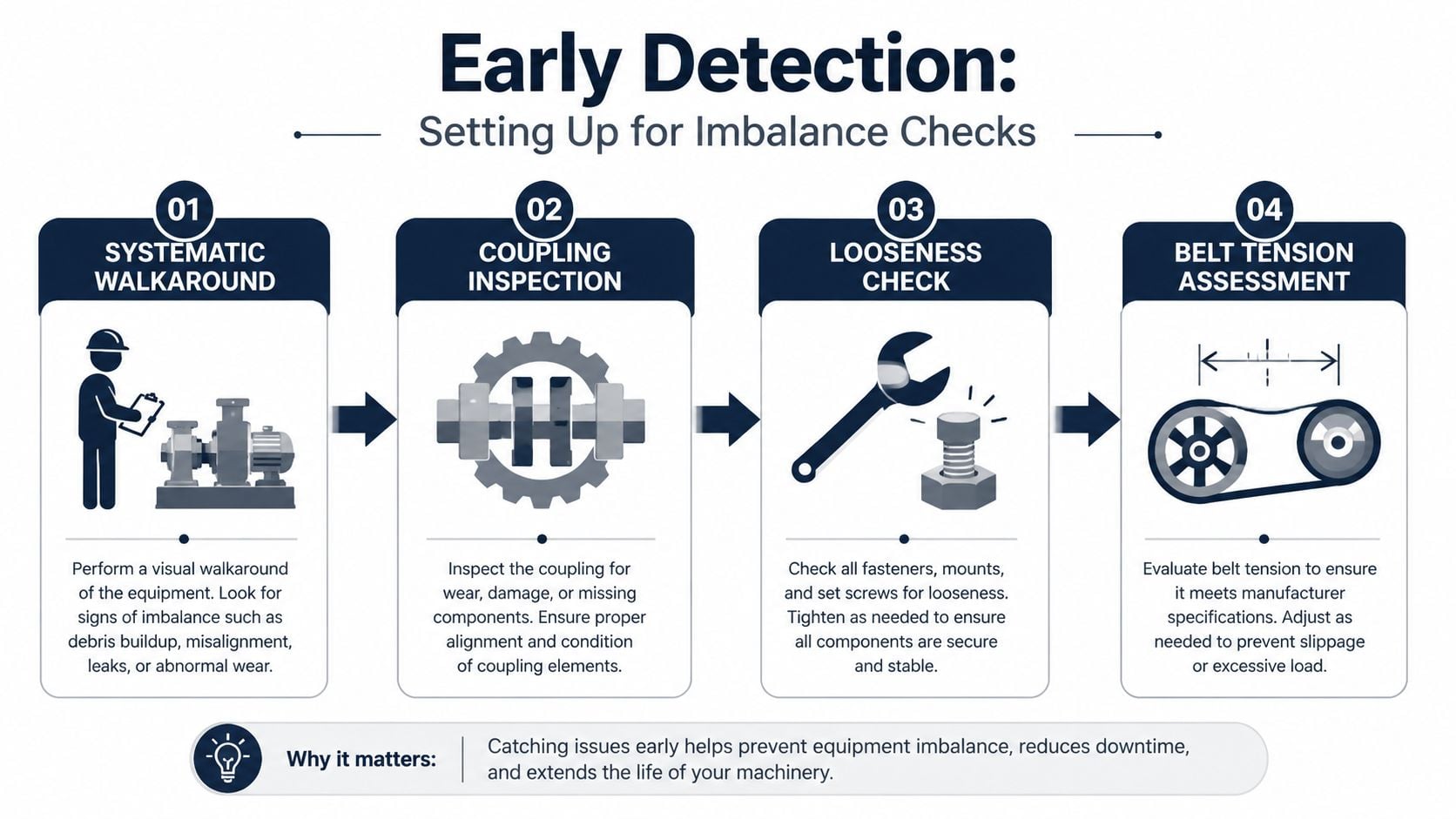
The first pass should be a disciplined walkaround of the machine train. On a pump and motor set, that means checking visible coupling condition, foundation integrity, hold-down hardware, piping strain indicators, guard contact points, and any sign that the rotor has been rubbing or carrying product buildup.
This visual pass should also look for clues that mimic unbalance:
- Coupling distress: Cracked inserts, fretting, or unusual wear can shift vibration patterns away from pure unbalance.
- Mechanical looseness: Elongated bolt holes, soft shims, and fretted feet can produce unstable amplitudes.
- Belt condition where applicable: Uneven belt tension can load bearings asymmetrically and distort readings.
- Rotor contamination: Dirt, corrosion, or product buildup at large radius creates a real mass eccentricity.
A simple flow helps technicians avoid skipping basics.
One mistake seen often is starting balance calculations on a machine with damaged bearings. A worn bearing can make phase readings wander. Once phase becomes unstable, the correction math loses validity.
Mount sensors where the force path is real
A good reading comes from a good mechanical connection. On pumps, motors, fans, and compressors, the best default mounting points are the bearing housings or stiff casing locations nearest the bearings. These points carry the dynamic force path more directly than thin guards, pipework, or cosmetic covers.
Sensor choice depends on the machine and objective:
- Accelerometers are preferred when the team wants a wider frequency view and stronger sensitivity to impact and high-frequency content.
- Velocity readings remain useful for overall machine severity and general balancing work on many process assets.
- Phase reference devices such as a tachometer or optical pickup are essential for dynamic balancing.
For teams standardizing routes and spot checks, this primer on the triaxial accelerometer sensor is useful when deciding how to collect repeatable data on multi-directional vibration.
A tachometer setup needs the same discipline. The target mark should be clean, the pickup should have a stable line of sight, and the signal should remain consistent throughout each run. If speed drifts between runs, the balancing result drifts with it.
Stable speed matters more than many teams admit. If one run is taken at a different operating speed than the next, the vector relationship changes and the calculated correction can land in the wrong place.
Before any balancing attempt, the machine should pass this minimum readiness check:
- Rotor clean enough to trust the mass distribution
- Bearings healthy enough to give stable phase
- Sensor mounts rigid and repeatable
- Tach signal clean and continuous
- Operating speed held constant during all runs
Collecting and Analyzing Vibration Data
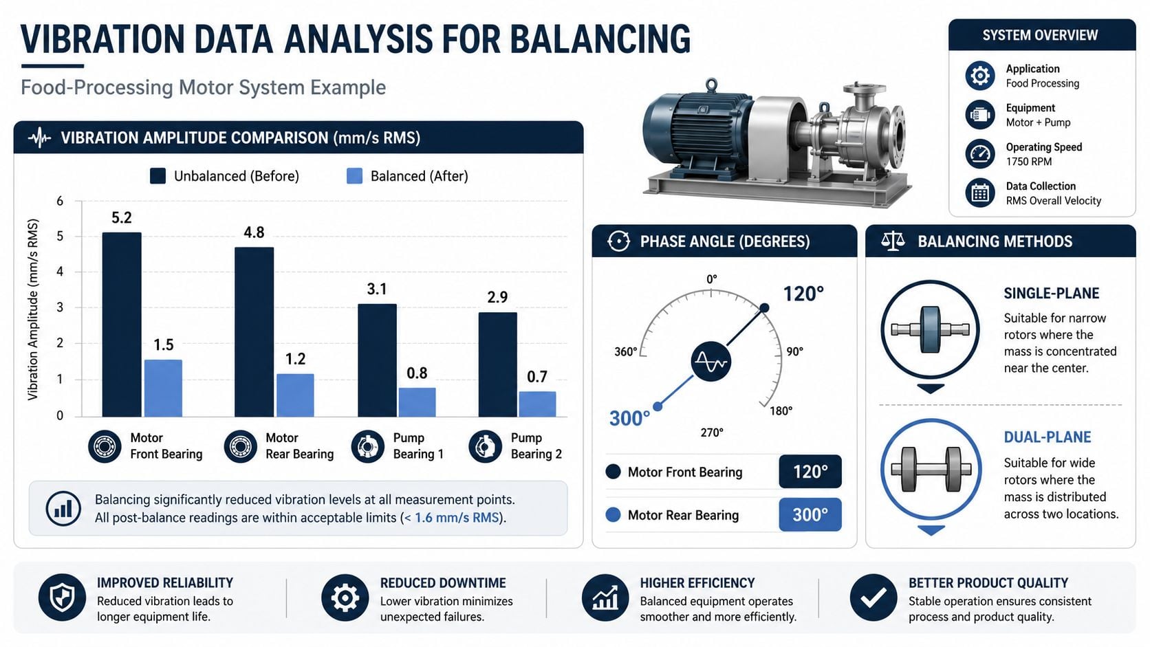
Balancing decisions should come from a pattern, not a single number. A food-processing motor driving a product pump is a good example because these trains often run in washdown areas, under changing load, with enough background noise to confuse weak data collection.
What the running data needs to show
The first target is the 1x running-speed component, which is the vibration frequency equal to shaft rotational speed. True unbalance usually shows up here as a dominant 1x response with a reasonably consistent phase relationship. That alone doesn't prove unbalance, but it's the right place to start.
Technicians should capture:
- Overall amplitude at each bearing location
- Phase at stable operating speed
- Spectrum shape around 1x
- Directional readings, typically horizontal and vertical, and axial when needed
- Operating condition notes such as load, temperature, and valve position
This is the minimum data set for making a balancing decision, and it aligns with the vibration measurement approach described here.
The balancing workflow itself should remain strict. The field rotor balancing methodology requires a strict four-step vector process: record initial amplitude and phase, install a trial weight to shift the vector, apply the calculated permanent weight, and perform a verification run to meet ISO 1940-1 tolerances, as outlined in Vibromera's field balancing guide.
A visual summary helps when training technicians on what “before and after” should look like in practical terms.
When the pattern is not unbalance
Misdiagnosing the cause of a strong 1x component often leads to wasted time for many teams. A strong 1x component can still come from other faults. A centrifugal fan, for example, may show increased 1x because the support structure is near resonance, because the base is loose, or because alignment is poor enough to distort the response.
The diagnostic question isn't “Can this machine be balanced?” It's “Is unbalance the dominant fault today?”
Useful indicators that support an unbalance diagnosis include:
| Indicator | What it suggests |
|---|---|
| Stable phase over repeated runs | Rotor response is consistent enough for balancing |
| Dominant 1x with limited distortion | Mass eccentricity is a likely primary driver |
| Similar response trend as load and speed remain steady | Data quality is good enough for correction |
| Clean vector shift after trial weight | The machine is responding like a balance problem |
Indicators that should stop the balance attempt include:
| Stop sign | Why it matters |
|---|---|
| Phase wandering between runs | Bearing, looseness, or speed instability may be corrupting data |
| Broad spectral peaks around 1x | Resonance may be amplifying the response |
| Strong axial vibration | Misalignment may be a larger issue |
| No clear response to trial weight | The assumed correction plane or fault diagnosis may be wrong |
A clean trial-weight response is often the best proof that the team is balancing the right problem. If the rotor doesn't respond logically, more weight won't fix the machine.
ISO tolerance checks matter at the end, not the beginning. Acceptance should be based on the rotor type and service, not on chasing the lowest number the instrument can display.
Balancing Methods and Calculation Procedures
Balancing rotating equipment is not one method. It's a set of methods, and the correct one depends on rotor geometry, service speed, support condition, and whether the machine's operating environment changes the vibration response.
When shop balancing makes sense
Shop balancing is still the right answer for many rotors. It offers control, repeatability, and better access for material removal or permanent correction. In production environments, the hard-bearing balancing method is projected to dominate 58% of the global balancing equipment market revenue in 2026, reflecting the speed and repeatability valued in high-volume work, according to Persistence Market Research.
Hard-bearing machines suit repeat rotor families well because the support system is stiff and the machine can process rotors quickly without extensive setup changes. For impellers, fans, and motor components that are routinely removed and processed in batches, shop methods often give the cleanest correction.
A refinery compressor impeller is a good example. If the rotor is accessible, the geometry is well understood, and the support condition in service is rigid and repeatable, a shop balance gives the maintenance team better control over correction locations and final quality.
This balancing map is useful when discussing the difference with planners and production teams.
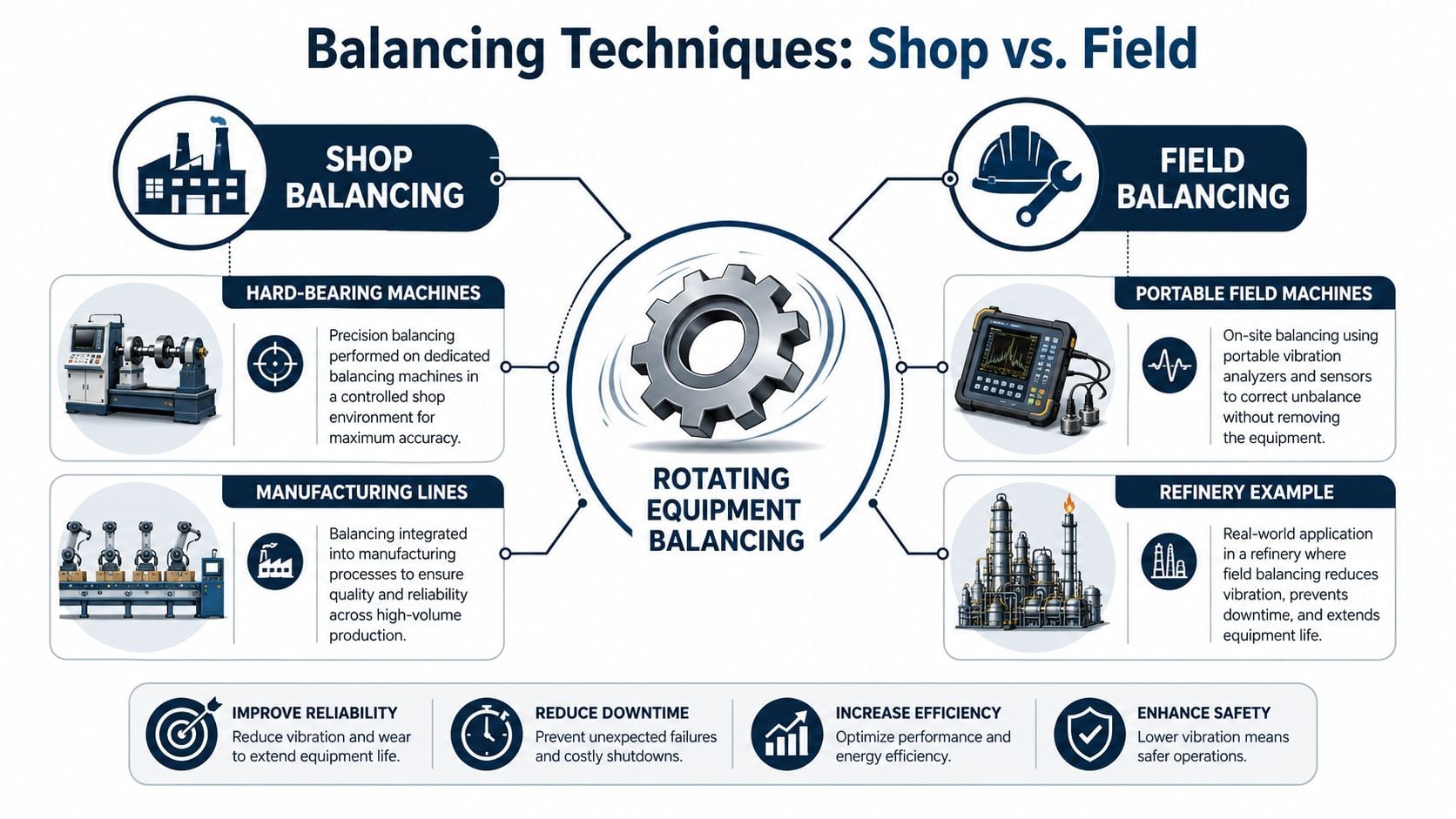
Shop work also aligns naturally with standards. ISO 1940-1, now ISO 21940-11, defines balancing acceptance through G-grades, and the same source notes that G6.3 allows up to 6.3 mm/s vibration for general machinery, while precision spindles may require G0.4 or lower. The same Persistence Market Research reference also states that ISO 16084 mandates that bearing loads caused by unbalance must not exceed 1% of the bearing's dynamic load capacity.
For machines operating near critical speeds, structural behavior matters too. Teams evaluating whether support flexibility or natural frequency is part of the problem should understand modal analysis fundamentals, because balancing won't solve a resonance problem built into the structure.
When field balancing is the better choice
Field balancing becomes the better option when the machine behaves differently in service than it does in a balancing shop. That happens more often than many teams expect. IVC Technologies notes that true operating conditions can make shop-balanced rotors fail immediately upon reinstallation, and that up to 30% of “balanced” rotors return to vibration complaints within weeks because the shop doesn't reproduce the machine's actual dynamic stiffness.
That problem shows up on machines with:
- Flexible or asymmetric supports
- Significant piping strain
- Thermal growth that changes shaft position in service
- Coupled trains where the rotor and system interact strongly
- Foundations that behave differently under process load
Power plant auxiliary equipment is a useful example because many of these rotors are relatively compact. For that application, E3S Conferences reports that rotating auxiliary equipment unbalance can generally be effectively solved by single-plane dynamic balance, which is a specific correction method distinct from multi-plane solutions for longer rotors.
A practical decision matrix
Instead of treating field balancing as a backup plan, use a decision matrix.
| Condition | Lean toward shop balancing | Lean toward field balancing |
|---|---|---|
| Rotor access | Rotor is already removed and easy to fixture | Rotor removal creates major outage scope |
| Support condition | Service support is rigid and repeatable | Foundation or supports change machine response |
| Rotor geometry | Correction can be made cleanly off-machine | Coupled system behavior dominates |
| Process sensitivity | Outage window allows controlled shop work | Fast in-place correction prevents larger disruption |
| Data behavior | Rotor response is predictable off-machine | Stable field phase data exists at running speed |
The calculation logic in the field remains straightforward even when the environment isn't. The workflow is:
- Record initial amplitude and phase at stable speed.
- Add a trial weight in a known angular location.
- Measure the new amplitude and phase.
- Calculate the correction weight and angle from the vector shift.
- Remove the trial weight and apply the permanent correction.
- Run a verification check and decide whether trim is still needed.
The most important trade-off is this. Shop balancing corrects the rotor. Field balancing can correct the rotor as installed in the machine system. That distinction matters on compressors, long fans, pump trains on questionable bases, and any machine that behaves differently once it is hot, coupled, and loaded.
Soft-Foot and Alignment Checks
Balancing results don't hold when the machine train is sitting on a distorted base. That's why soft-foot and alignment checks belong in the balancing workflow, not after it.
Soft-foot first
Soft-foot means one or more machine feet don't sit flat on the baseplate. When a technician torques the hold-down bolts, the casing distorts. That distortion changes bearing alignment, shifts shaft centerline position, and alters vibration behavior. A machine can look balanced and still run badly because the frame is being twisted into shape.
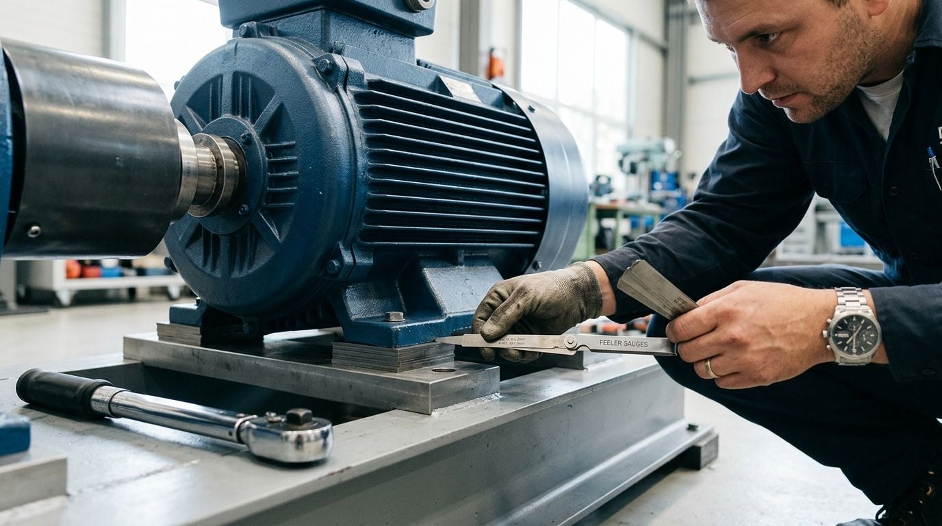
The practical soft-foot check is simple:
- Isolate and lock out the machine.
- Verify base cleanliness under each foot.
- Loosen one foot at a time while monitoring the gap or movement.
- Use feeler gauges to identify the unsupported foot.
- Correct with clean, flat shims.
- Retorque in sequence and recheck.
Common causes include bent feet, dirty shim packs, poor machining, and pipe strain pulling the machine frame out of position.
Alignment after balancing correction
Once the machine sits correctly, alignment becomes meaningful. A pump and motor set should go through rough alignment first, then fine alignment using dial indicators or a laser system. The point isn't the tool. The point is to bring both shafts into acceptable offset and angular relationship under actual hold-down conditions.
Teams often chase unbalance when the machine is reacting to another fault. Engineers frequently ask, “How do I know if I'm balancing the right problem?” because 20–40% of vibration attributed to “unbalance” is caused by resonance, rubs, or mechanical looseness that balancing exacerbates rather than resolves, according to Acoem's balancing guide.
A shaft train with poor alignment can produce a strong running-speed response that looks balance-related from a distance. It isn't. This reference on shaft misalignment is a useful refresher when the machine shows increased axial vibration, coupling distress, or changing readings after hold-down torque.
If a machine needs repeated trim corrections after every restart, check base condition and alignment before adding more weight. Recurrent “unbalance” is often a symptom, not the root cause.
Balancing should be the last correction applied to a mechanically stable machine, not the first attempt to calm an unstable one.
Practical Tips and Common Failure Modes
The biggest trap in balancing rotating equipment is treating every vibration complaint as a rotor mass problem. Field conditions often decide the outcome. IVC Technologies notes that most guidance treats field balancing as a quick fix when shop balancing is unavailable, while overlooking how true operating conditions can make shop-balanced rotors fail immediately after reinstallation.
Common Failure Modes and Diagnostic Focus
| Equipment | Failure Mode | Diagnostics |
|---|---|---|
| Centrifugal pump | Impeller buildup or erosion pattern | Check 1x vibration trend, inspect impeller condition, review process deposits |
| Motor | Soft-foot or base distortion | Loosen feet one at a time, inspect shim condition, recheck phase stability |
| Gearbox-driven train | Coupling looseness | Inspect coupling wear, verify fastener torque, compare radial and axial response |
| Fan | Blade contamination | Visual rotor inspection, check for stable 1x and repeatable phase |
| Pump-motor set | Misalignment masking as unbalance | Review axial vibration, coupling condition, and alignment readings |
For maintenance teams that also work across vehicle or mobile powertrain systems, the failure logic behind vibration and torque transmission has parallels with understanding auto transmission failures, especially around how secondary mechanical defects can look like a primary rotating fault.
What usually works and what wastes time
A few field rules save hours:
- Use the right correction plane: Narrow rotors usually respond cleanly to single-plane work. Longer rotors may need multi-plane correction.
- Target a clear trial response: The trial weight should produce an obvious vector shift. If the response is muddy, the diagnosis or setup may be wrong.
- Don't chase a perfect number: Stop when the residual vibration is acceptable for the machine class and the response is stable.
- Choose field balancing when the machine behaves differently in service: Hot alignment growth, support flexibility, and piping effects all push the decision toward in-place correction.
- Choose shop balancing when access and control matter more than installed behavior: Removed rotors, repeat parts, and controlled correction points favor the shop.
The balancing method must match the rotor geometry and operating conditions, and the result should always be verified by before-and-after data, as noted by IVC Technologies in this review of poor balancing failures.
Documentation Safety and Specialist Support
A balancing job isn't complete until the data is recorded in a way the next technician can trust. The maintenance record should include initial readings, phase data, trial weight location, correction weight location, final verification results, alignment findings, and any soft-foot correction made during the work. That documentation belongs in the CMMS with enough detail to support future troubleshooting.
Safety discipline matters just as much. Lockout-tagout, secure guarding practices, PPE around rotating shafts, and controlled handling of weights are basic requirements. Plants that need a stronger framework for these routines often benefit from guidance on how to build a compliant H&S system, especially when balancing work is done across multiple trades and contractors.
Specialist support is warranted when vibration persists after a logical correction sequence, when phase data won't stabilize, when the machine is highly critical, or when structural behavior suggests resonance rather than unbalance. At that point, more trial weights won't help. Better diagnostics will.
If recurring vibration, bearing failures, or repeated trim balancing are consuming outage time at the plant, Forge Reliability can help assess the machine train, identify whether unbalance is really the primary fault, and build a practical correction plan. Request a free reliability assessment to review critical assets, tighten diagnostic workflows, and reduce avoidable downtime.