A maintenance manager usually starts looking at a triaxial accelerometer sensor after a familiar failure pattern shows up. A pump trips on vibration, a motor comes back from alignment, the route still says vibration is “acceptable,” and then the bearing fails anyway. The problem often isn't that the plant has no vibration program. The problem is that the program is only seeing one slice of machine motion.
That matters most on critical rotating assets. Pumps, fans, motors, and gearboxes rarely fail in a single clean direction. They move axially, radially, and vertically at the same time, and each direction can carry a different fault signature. A triaxial accelerometer sensor can help, but only when the plant uses it for the right assets, mounts it correctly, and matches the sensor to the failure mode that matters.
Table of Contents
- The Triaxial Advantage Over Single-Axis Sensors
- Decoding Key Sensor Specifications for Fault Detection
- Selecting the Right Sensor for Your Critical Assets
- Installation Best Practices to Ensure Data Integrity
- Interpreting Triaxial Data for Accurate Diagnostics
- Real-World ROI From Triaxial Analysis Case Studies
The Triaxial Advantage Over Single-Axis Sensors
A centrifugal pump can pass a route with a single-axis reading and still hide the reason it keeps eating bearings. That happens when the route captures one radial direction well enough to trend overall vibration but misses strong axial motion or a directional change tied to misalignment, pipe strain, looseness, or a bearing defect developing in another plane.
Why one direction often isn't enough
A single-axis sensor is useful. It isn't useless or obsolete. It just answers a narrower question: what is the machine doing in this one direction at this one point?
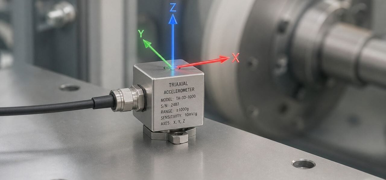
A triaxial accelerometer sensor answers a different question: what is the machine doing in three directions at the same time? By the 2000s, triaxial designs were in widespread adoption, with the key advantage of measuring acceleration on three axes, X, Y, and Z, and that multi-axis capability made them valuable for condition-based maintenance on rotating equipment.
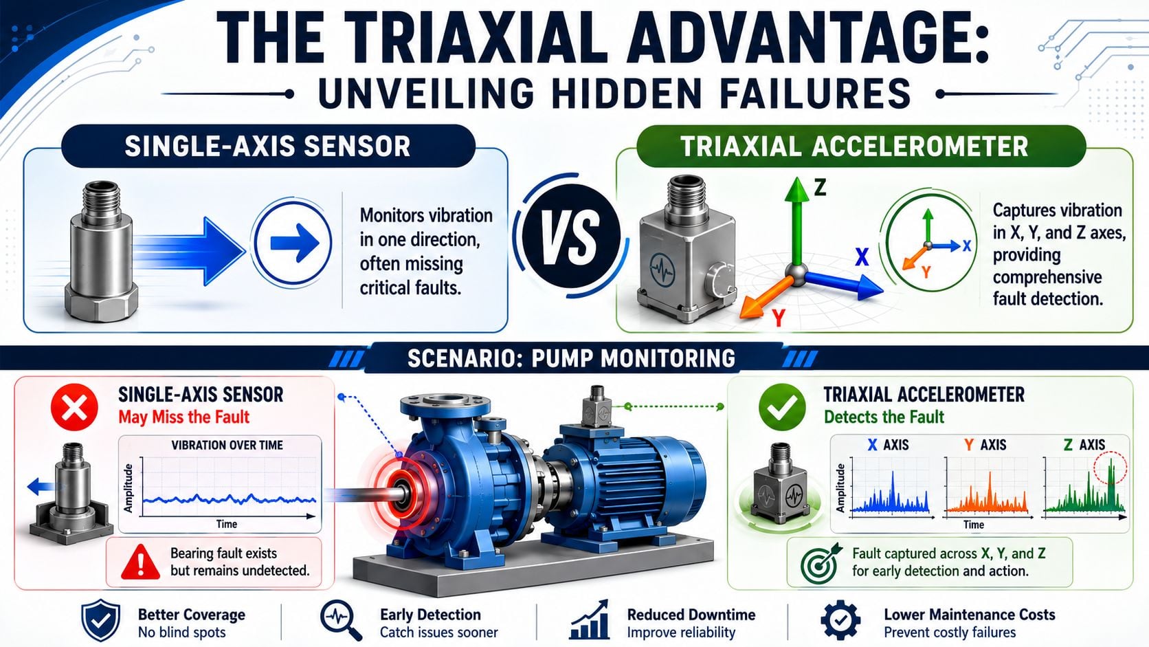
On a pump, that difference is practical, not academic. The axial direction often helps expose coupling and alignment issues. One radial direction may show imbalance clearly. The second radial direction can show structural response, base looseness, or different stiffness effects. When those three views are captured simultaneously, the analyst can compare motion patterns instead of guessing from one isolated line.
Practical rule: If the asset is critical and the likely failure modes can express differently by direction, one-axis data is often incomplete data.
A maintenance manager can think of it as machine vision. Single-axis monitoring is like inspecting a rotating shaft with one eye closed. A fault may still be visible, but depth, direction, and relative motion are harder to judge. Triaxial data gives the analyst a fuller picture of the machine's actual behavior.
What the extra axes actually change
The extra value isn't “more data” by itself. More data can make analysis worse if nobody uses it well. The value is simultaneous directional context.
That matters on assets such as:
- Motor-pump sets: High axial activity can support a misalignment suspicion, while uneven radial response can point toward looseness or stiffness differences.
- Fans: Comparing vertical and horizontal vibration helps separate rotor-driven vibration from structural problems in the support.
- Gearboxes: Directional changes across axes can make it easier to judge whether the casing is responding to internal mesh activity, mounting issues, or both.
- Bearing locations: A developing defect may appear more clearly in one direction than another depending on load path and housing geometry.
A triaxial accelerometer sensor also reduces the need to reposition a sensor for each direction. That improves consistency and shortens collection time, especially on route-based programs. For teams building motor routes, vibration analysis of motor assets becomes much more useful when the sensor captures axial and radial behavior together instead of forcing three separate placements.
A triaxial sensor doesn't replace analysis skill. It gives the analyst a better chance to see the fault pattern before maintenance burns time on the wrong corrective action.
The plants that benefit most are the ones with recurring failures that don't fit a simple imbalance story. If a pump has already been balanced, aligned, and rebuilt more than once, the next step usually isn't another blind correction. It's better directional evidence.
Decoding Key Sensor Specifications for Fault Detection
Buying a triaxial accelerometer sensor by brochure language usually leads to one of two mistakes. The plant either pays for a sensor with capabilities it won't use, or it installs a cheap sensor that can't capture the frequencies tied to the failure modes it cares about.
Sensitivity, bandwidth, and dynamic range in plant terms
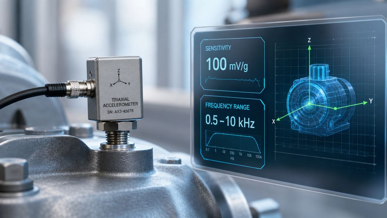
Sensitivity is typically expressed in mV/g, meaning millivolts of electrical output per unit of acceleration. In plain terms, higher sensitivity helps the analyst see smaller vibration signals more clearly. That matters on lower-energy machines or early-stage defects where the signal can be faint.
Bandwidth is the frequency range the sensor can capture effectively. For condition monitoring, triaxial accelerometers are commonly specified with bandwidths up to 15 kHz, which matters because bearing defects, gear mesh harmonics, and looseness can produce higher-frequency content that low-bandwidth sensors may miss. A compact triaxial example also shows 108 dB dynamic range and cross-axis sensitivity under 5%, which highlights the trade-offs reliability engineers need to judge for early-stage detection work (technical overview of triaxial accelerometer performance).
Dynamic range describes how well the sensor can handle very small and much larger signals without losing useful information. A wider dynamic range helps when a machine has low-level defect energy riding on top of stronger running vibration. That's common on pumps and motors that still operate but already have a rolling element bearing defect starting to emerge.
How to read a datasheet against a failure mode
The right way to read a datasheet is to start with the machine and fault, not the sensor.
For a centrifugal pump in a process plant, the team usually wants to detect some combination of imbalance, misalignment, hydraulic disturbance, looseness, and bearing deterioration. That means the selection process should look like this:
Define the likely failure modes first.
A pump with coupling issues and repeated seal failures needs clean axial and radial measurement. A gearbox-driven pump with bearing history needs enough high-frequency capability to support early defect work.Ask what part of the signal matters.
If the concern is general running condition and gross mechanical issues, a moderate bandwidth may be enough. If the concern is early bearing fault detection, the team needs a sensor and collection setup that preserve higher-frequency content.Match sensitivity to machine behavior.
A lightly loaded fan or slower-speed asset may need stronger low-level signal resolution. A harsher machine may need a range that won't saturate under higher shock or vibration.Check cross-axis behavior.
In triaxial sensing, poor isolation between axes muddies diagnosis. If the machine already has complex motion, the analyst needs confidence that a strong signal in one direction isn't heavily contaminating the others.
The sensor isn't “good” or “bad” in isolation. It's either suited to the fault signature on that asset, or it isn't.
A common specification error is choosing a sensor based on overall vibration trending only, then expecting it to support advanced diagnostics later. That's where bearing work often breaks down. Another mistake is overbuying a wide-range sensor for a low-energy asset and ending up with less useful sensitivity than the route really needed.
A maintenance manager should ask one blunt question before approving a sensor: What fault is this sensor supposed to catch earlier than the current setup? If nobody can answer that, the plant is buying hardware, not diagnostic capability.
Selecting the Right Sensor for Your Critical Assets
A triaxial accelerometer sensor makes the most sense where directional behavior affects the maintenance decision. That includes assets where the plant needs to separate imbalance from misalignment, structural response from rotor response, or bearing activity from process-related vibration.
Where triaxial sensing earns its place
A triaxial sensor is typically built as three orthogonal accelerometers in one package, so it captures X, Y, and Z vibration at the same time. Industrial quartz triaxial models are available in ranges from 25 to 500 g with sensitivities from 10 to 200 mV/g, which shows that these sensors can be selected for both low-level motion and high-shock machinery environments (industrial triaxial accelerometer configuration and ranges).
That range matters because plants don't monitor one type of machine. A cooling tower fan, a process pump, and a reciprocating compressor don't ask the same question of a sensor.
Use triaxial sensing when the asset has one or more of these traits:
- The asset is critical to production. Failure consequences justify richer directional data.
- The machine has recurring vibration that isn't solved by simple balancing.
- The support structure influences vibration response. Fans and skid-mounted machines often fit this pattern.
- The team needs fewer sensor moves per route. Simultaneous three-axis capture improves repeatability.
- The plant may convert from route-based to permanent monitoring later.
For broader planning across routes, online systems, and asset criticality, asset management strategies for vibration monitoring equipment can help teams decide where a triaxial accelerometer sensor belongs and where a simpler approach is still enough.
Triaxial sensor selection guide by asset type
The table below isn't a purchase spec. It's a decision aid that ties machine behavior to sensor priorities.
| Asset Type | Primary Failure Modes | Required Sensitivity | Required Frequency Range | Example Industry |
|---|---|---|---|---|
| Process pump | Imbalance, misalignment, bearing wear, hydraulic disturbance, looseness | Moderate to high sensitivity for mixed mechanical and bearing signals | Broad enough for running-speed faults and higher-frequency bearing content | Chemical processing |
| Large motor | Misalignment, soft foot, bearing wear, electrical-mechanical interaction, looseness | Moderate sensitivity with strong directional clarity | Broad enough to trend running condition and support bearing evaluation | Water and wastewater |
| Cooling tower fan | Imbalance, structural looseness, blade-related issues, bearing wear | Higher sensitivity for slower-speed, lower-energy vibration | Moderate to broad, depending on bearing strategy | HVAC and utilities |
| Gearbox | Gear mesh issues, bearing defects, looseness, misalignment | Moderate sensitivity with strong high-frequency usefulness | Higher-frequency capability is important | Pulp and paper |
| Reciprocating compressor | Mechanical looseness, impacting, crosshead-related vibration, valve issues | Sensor must tolerate harsher vibration while preserving useful detail | Broad range for complex forcing and impact behavior | Oil and gas |
A few practical choices follow from that table.
- Pumps and motors: Triaxial sensing usually earns its keep fast because axial motion changes the diagnosis.
- Fans: Use it when the plant needs to separate rotor issues from support or base problems.
- Gearboxes: Choose it when bearing and mesh-related content matter, not just overall casing shake.
- Reciprocating equipment: Don't assume triaxial automatically solves diagnostics. Harsh motion can complicate interpretation, so sensor ruggedness and mounting discipline matter more.
Selection shortcut: If two different corrective actions are possible and directionality is what separates them, a triaxial sensor is usually worth the complexity.
One measured mention is useful here. Some service providers, including Forge Reliability, collect tri-axial vibration measurements at each bearing housing as part of condition monitoring programs. That approach fits plants that want consistent direction-based diagnostics without building all of the analysis capability in-house.
Installation Best Practices to Ensure Data Integrity
Most failed triaxial programs don't fail because the sensor was technically wrong. They fail because the mounting point was poor, the surface prep was sloppy, the orientation was inconsistent, or the route team changed methods from one collection to the next.

Mounting quality decides data quality
The best sensor still reports the motion of whatever it is attached to. If it's mounted on paint, corrosion, a thin cover, or an area with poor structural coupling to the bearing housing, the signal can be distorted before analysis even starts.
Stud mounting generally gives the highest fidelity. It provides a more rigid mechanical path from machine to sensor, which matters when the team wants clean high-frequency information. Magnetic mounting is convenient for route collection, but convenience comes with trade-offs. The mount can change the usable response, especially when the plant is trying to preserve subtle higher-frequency defect content.
Orientation matters just as much. On a motor-pump set, the sensor axes should be aligned consistently with the machine's axial and radial directions. If one route places X on axial and the next route rotates the sensor body, the trend may still exist, but directional comparison becomes much less trustworthy.
Bad mounting can make a healthy machine look rough, and it can make a rough machine look acceptable.
Field practices that prevent bad data
A plant gets better triaxial data when technicians treat installation as part of the diagnostic method, not as a minor setup step.
- Prepare the surface: Remove loose paint, rust, oil, and debris. The sensor needs a clean, solid contact point near the bearing housing or another structurally meaningful location.
- Standardize the point: Use the same point and same orientation every time. Route consistency matters more than technician preference.
- Control the cable: Unsupported cable movement can add noise. Secure the cable so it doesn't whip or rub during collection.
- Choose the right location: Don't mount where guards, thin covers, or local resonances dominate the response unless that's the behavior being studied.
- Document axis orientation: Label which axis is axial, vertical, and horizontal for each point in the route database.
A route-based team also needs a repeatable setup document. Plants that struggle with this should formalize point naming, mounting method, orientation photos, and collection instructions. A good starting point is a structured vibration monitoring route setup guide.
Another common mistake is chasing machine centerline symmetry too closely. The best measurement point isn't always the most visually centered one. It's the point that best represents the load path into the housing and can be repeated safely and consistently.
Interpreting Triaxial Data for Accurate Diagnostics
Once the plant has clean three-axis data, the job changes from collection to judgment. The analyst isn't looking for the loudest line alone. The analyst is looking for relationships across axes, frequencies, and waveform behavior.
How analysts use the three axes together
Modern diagnostics sit on a long technical foundation. In 1943, the first commercial piezoelectric accelerometer, the Type 4301, was developed with a measured sensitivity of 35 to 50 mV/g and a resonant frequency of 2 to 3 kHz. Later advances, including 1964 compression-type accelerometers, reduced susceptibility to case loading and base strain, which helped make accelerometer-based work practical in industrial environments (historical development of industrial accelerometers).
That history matters because triaxial interpretation depends on confidence in the signal. Once the data is trustworthy, analysts usually work with a combination of tools:
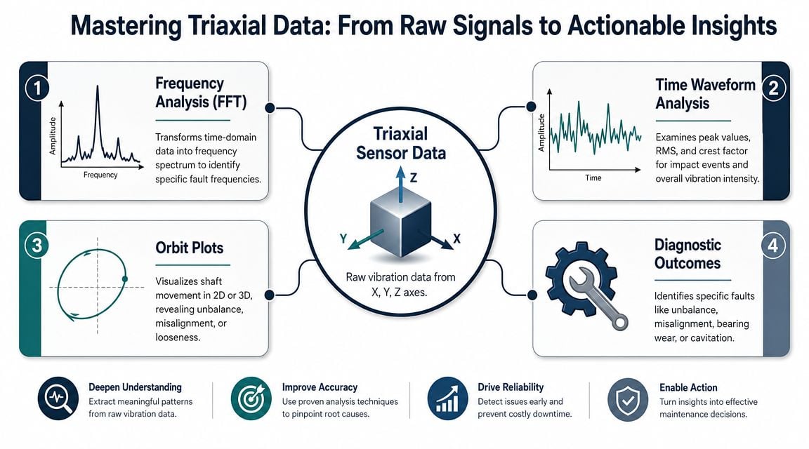
- FFT or frequency spectrum: Separates the signal into frequency components so the analyst can compare running speed, harmonics, and defect-related content.
- Time waveform: Shows impacts, modulation, repeating events, and changes in signal shape that overall numbers can hide.
- Axis comparison: Reveals whether the machine response is primarily axial, radial, vertical, or mixed.
- Envelope or bearing-focused processing: Helps expose repeating high-frequency impacts associated with rolling element defects when the collection setup supports that method.
For teams focused on bearing work, bearing fault detection using vibration analysis becomes stronger when the analyst can compare defect evidence across three directions instead of relying on a single spectrum.
What different axis patterns usually mean
There is no universal one-pattern-one-fault rule. Machines are messier than that. Still, some directional patterns are consistently useful.
On a motor coupled to a process pump, significant axial vibration often pushes the analyst toward coupling alignment, bent shaft concerns, or mechanical fit issues. If radial directions are modest but axial energy stands out, the correction path may be very different from what a single radial point would suggest.
On a fan, vertical versus horizontal differences can be revealing. If one radial direction dominates because the structure is weak in that plane, the issue may not be simple rotor imbalance. The plant may need to address support stiffness, hold-down condition, or soft foot before another balance job.
A gearbox often produces a mixed picture. The analyst may see casing response in more than one axis, with one direction carrying stronger gear-related energy and another carrying more structural response. Triaxial data helps separate “the gearbox is generating this” from “the foundation is amplifying this.”
Don't diagnose from one axis in isolation when the three axes disagree. The disagreement is often the clue.
A chemical plant pump provides a good example. Suppose the horizontal axis shows increased running-speed vibration, the vertical axis is moderate, and the axial axis also rises with coupling-side activity. That pattern may support a combined diagnosis rather than a single one. The machine could have imbalance plus misalignment, or a structural condition that is amplifying an otherwise moderate rotor issue. The maintenance action then changes from “balance it” to “inspect alignment, base condition, and coupling together.”
Time waveform review is also where triaxial work earns respect. A waveform with repetitive impacts in one axis but not the others can shift the investigation toward localized looseness, bearing damage, or intermittent contact. When those impacts line up with fault-related spectral features, the diagnosis becomes much stronger.
Real-World ROI From Triaxial Analysis Case Studies
The business case for a triaxial accelerometer sensor isn't that it produces more channels. The case is that it can change the maintenance decision early enough to avoid the wrong repair, the wrong outage scope, or a repeat failure.
When triaxial data changes the maintenance decision
A food processing plant with a packaging line gearbox is a good example. A single-axis route may trend overall vibration adequately but still leave the team uncertain whether the change is gear-related, bearing-related, or structural response from the frame. Three-axis data can clarify which direction carries the most actionable content, helping the planner decide whether to inspect the gearbox internals during a scheduled stop or keep watching.
A remote compressor package in oil and gas offers another case. The maintenance team may suspect alignment drift, but one direction alone can't separate that from a broader structural or piping-related response. Triaxial data is useful when the directional pattern supports a mechanical correction instead of a premature component swap.
In a power plant pump train, the issue is often compounded faults. The machine may show signs of imbalance and foot or base condition at the same time. A triaxial set lets the analyst build a more complete case before the outage crew starts work. That usually leads to better scope definition, fewer return visits, and less debate between maintenance and operations about what caused the event.
When it only adds complexity
This is the part many articles skip. Three axes do not automatically equal a reliable diagnosis.
A key issue for reliability teams is that the actual limitation may be mounting location or frequency range, not the number of axes. Even validation work has shown that angle reconstruction can be accurate under static conditions while dynamic error increases with angular acceleration, which is a useful reminder that “3 axes” alone doesn't solve motion-heavy applications (discussion of triaxial sensing limits and dynamic error).
That means triaxial sensing can become noise if the plant does any of the following:
- Mounts the sensor in the wrong place: The data is still rich, but it's rich in the wrong response.
- Chooses insufficient bandwidth: Higher-frequency bearing or gear content won't be captured well enough to support the diagnosis.
- Applies it to noncritical assets without a use case: More channels create more review time with little decision value.
- Lacks analysis discipline: Teams collect three directions and still make decisions from overall values only.
The return comes when the plant uses triaxial sensing on machines where direction changes the remedy. That can reduce repeat work, improve outage planning, and strengthen root-cause clarity. Plants looking at the broader financial side of those decisions should connect condition monitoring choices to maintenance cost reduction priorities, not just to sensor count.
A plant doesn't need triaxial sensors everywhere. It needs them where they help answer a maintenance question the current setup can't answer cleanly.
Forge Reliability offers free reliability assessments for plants that need help deciding where a triaxial accelerometer sensor fits into route-based monitoring, permanent monitoring, or a broader predictive maintenance program. For maintenance leaders dealing with recurring pump, motor, fan, or gearbox failures, that assessment can identify whether the gap is sensor choice, mounting practice, analysis method, or asset strategy.