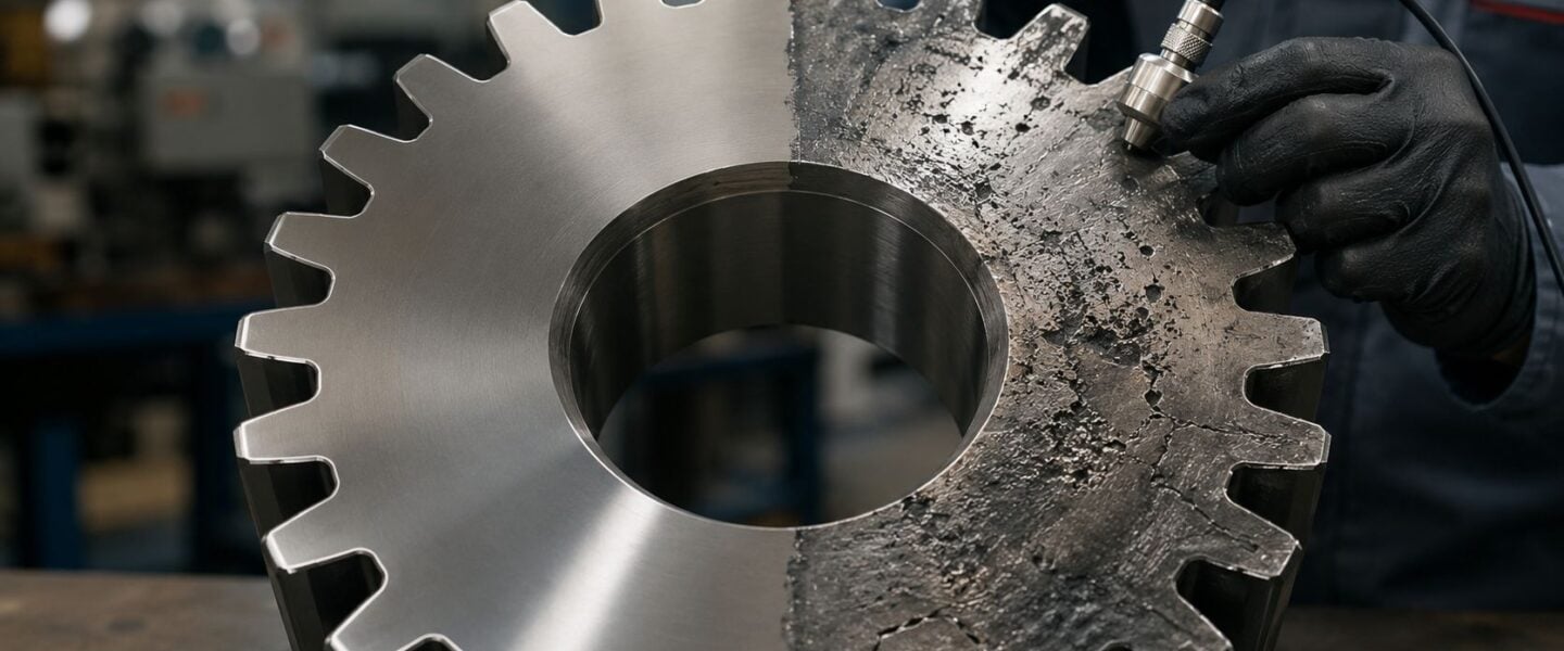
A gearbox does not usually announce its failure with a neat, textbook symptom. A mill drive starts sounding harsher on Monday, a pump-train reducer runs a little warmer after a lube upset, or a conveyor gearbox keeps going until a tooth lets go during a routine start. By the time a crew opens the housing, the visible damage often hides a mixed failure story, where fatigue, contact distress, wear, scuffing, and overload all showed up together in different forms.
That is why the useful question is not, “What failed?” It is, “What combination of loading, lubrication, alignment, metallurgy, and monitoring gaps let the failure progress?” The most reliable plants treat gear failure modes as a diagnostic problem, not a parts-ordering problem. That mindset saves rebuilds from turning into repeat events, which is exactly where many teams get trapped.
Table of Contents
- Why Gear Failures Keep Catching Plants Off Guard
- The Core Mechanisms Behind Gear Failure Modes
- Bending Fatigue, Pitting, Scuffing, and Fracture in Practice
- Matching Diagnostic Tools to Specific Gear Defects
- How the Same Gear Failure Plays Out Across Industries
- Choosing the Right Monitoring Strategy for Critical Gearboxes
- Building a Mitigation Plan That Prevents Repeat Failures
- Your Next Step Toward Gearbox Reliability
Why Gear Failures Keep Catching Plants Off Guard
A maintenance crew opens a gearbox on a cement kiln fan or a paper machine drive and expects one clean cause. Instead, they often find a mixed pattern, a worn flank, a crack at the tooth root, darkened oil, and bearing distress nearby. That is consistent with field data from a 35-year database of 931 gear failure cases, where the biggest categories were fatigue tooth fracture (32.8%), surface fatigue (20.3%), overload tooth fracture (19.5%), and surface wear (13.2%) (gear failure case history).
Those numbers matter because they show the trap. A plant that treats every gear problem as “just wear” misses the fact that root bending fatigue and contact-related damage account for a large share of observed failures, while overload and wear still remain important contributors. In other words, the gearbox is rarely failing for one reason only, and the visible symptom is often the last chapter, not the first.
Why “Replace the Gear” Often Fails
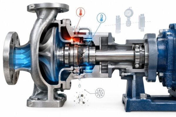
A replacement on its own can be the wrong corrective action when the system still has the same stress path. In an industrial gearbox, that usually means the same misalignment, the same contaminated lubricant, the same transient overloads, or the same bearing looseness that loaded the tooth in the first place. The result is predictable, the new gear starts to show distress long before the crew expected it.
Practical rule: if the root cause is still active, the rebuild becomes a temporary reset, not a repair.
The better approach is to treat the gearbox as part of a load chain. That means checking the drive motor, couplings, shaft supports, lubricant condition, seal integrity, and duty profile, not just the tooth flank. An inspection program built around that systems view is more likely to prevent the same failure from returning after the next shutdown. A useful starting point for that kind of field discipline is the industrial gearbox maintenance and inspection overview, especially for teams trying to move from reactive repair to repeatable prevention.
A practical example is a conveyor gearbox in bulk handling. If dust ingress raises contamination levels and the team only changes the gear, the next set of teeth still runs through the same dirty oil. The failure mode changes slowly, but the downtime does not.
The Core Mechanisms Behind Gear Failure Modes
A gearbox can run quietly for months, then one tooth starts to shed metal, and the failure path becomes clear only after teardown. The surface story often looks simple at first, but the cause usually sits in the interaction between load path, lubrication, metallurgy, and the way the machine is being operated.
The Main Mechanisms in Plain Language
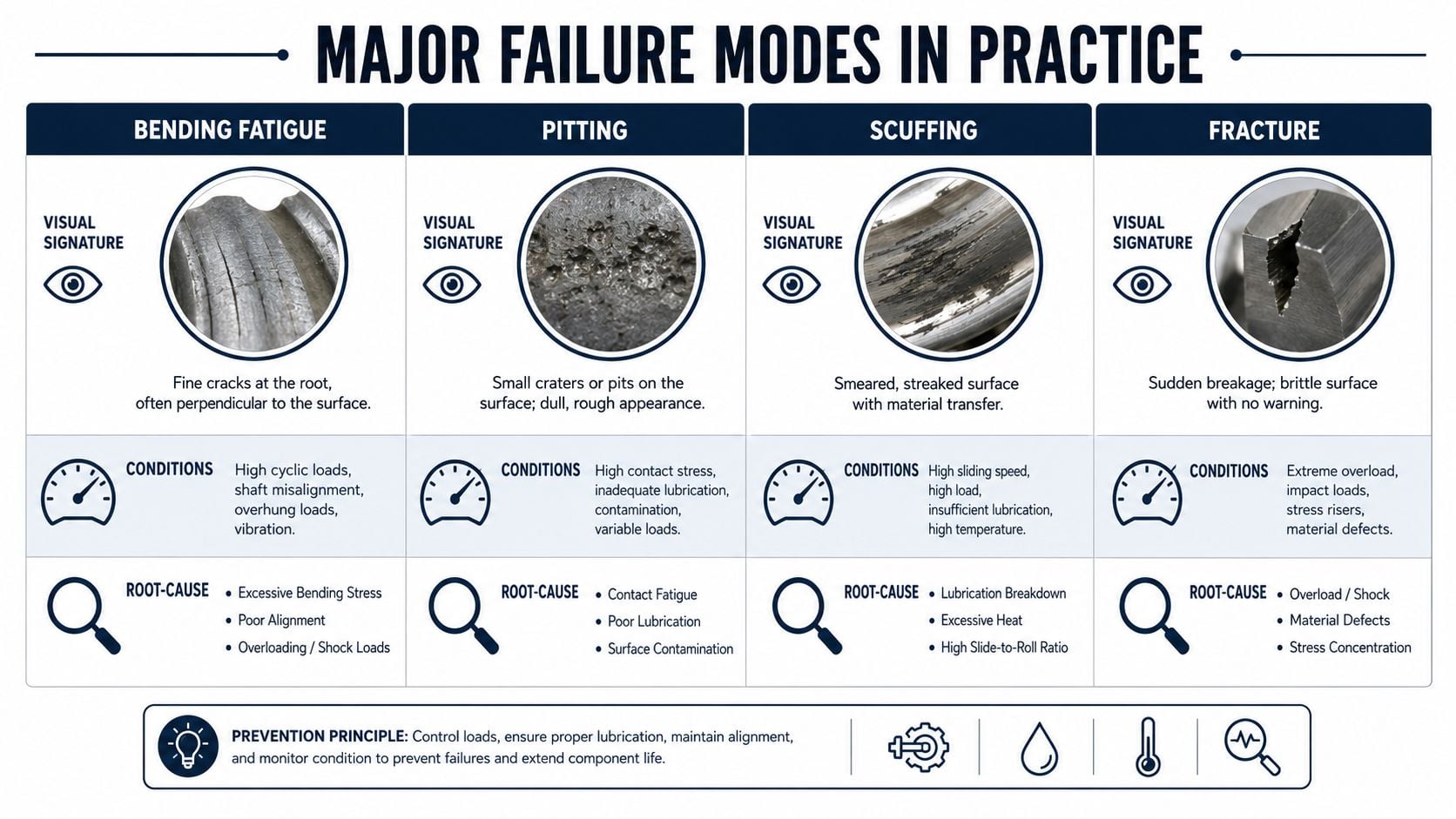
Bending fatigue starts at the tooth root, where repeated flexing opens a crack that grows until the tooth lets go. The paper-clip comparison is accurate enough for field work, a tooth can look acceptable until that crack reaches a critical size and the break becomes sudden. Root stress rises fastest near geometry changes, inclusions, and notch-like discontinuities, and it also depends on how the load is carried through the mesh and adjacent supports, including whether the system is taking more radial or axial load than the design intended (gear failure modes and analysis, radial vs axial load).
Contact fatigue works differently. The flank is loaded repeatedly under Hertzian contact stress, the concentrated stress that forms when curved surfaces press together. A hard ball pressed into a surface is a useful mental picture, because the material may survive many cycles and then begin to show pitting or flaking once stress, alignment, and lubrication no longer keep the contact patch protected.
The infographic below captures the four failure types that show up most often in practical discussions.
Why Secondary Damage Can Mislead the Crew
Wear is material removal from the tooth surface. Scuffing is more severe, it happens when the protective lubricant film breaks down and the surfaces slide in metal-to-metal contact, which can smear and tear the flank. Overload fracture comes from a load event, often shock loading or severe misalignment, where the gear breaks because the applied stress exceeded the part's capacity.
The hard part is that a failed tooth often carries more than one signature. A tooth can begin with contact fatigue, then develop a crack, then break, and the broken fragment can create secondary scuffing and wear on nearby teeth. That is why failure analysis has to separate the primary mode from the secondary damage before any repair decision is made.
For gearbox troubleshooting in a steel mill or a crusher drive, that distinction changes the plan. A surface problem pushes the crew toward lubrication, contamination, and alignment checks. A bending problem points toward load path, tooth root condition, shaft support, and transient event review. A fracture problem can require a wider look at overload, shock, or mounting errors, because the tooth is only the last part to fail.
Bending Fatigue, Pitting, Scuffing, and Fracture in Practice
What the Tooth Is Telling You
A gearbox rarely fails with just one clean symptom. A tooth can start with root distress, pick up surface damage from changing contact conditions, and only then break in a way that makes the final event look like the original cause.
Bending fatigue shows up at the tooth root, often as a crack that grows from the root fillet toward the tooth body. The operating pattern usually involves repeated loading, misalignment, or a tooth root stress concentration. In a crusher gearbox, that can mean the tooth survives normal running, then fails after repeated impact during startup or jam release.
Pitting appears on the flank as small craters or surface breakouts. Macropitting is the larger, more obvious form, while micropitting is finer surface distress that can be easy to miss early. Both point toward repeated contact stress, and both get worse when lubrication film thickness is poor or contamination starts to disturb the contact zone.
Scuffing and scoring are different again. They signal boundary lubrication or lubricant breakdown, so the flank is no longer separating cleanly under load. That is common in hot service, during inadequate oil supply, or when a gearbox sees load before the lubricant reaches the right condition.
When scuffing shows up, lubrication is part of the answer, but load and speed history still matter. A fix that ignores duty cycle usually disappoints.
A cracked tooth root and a torn flank do not point to the same recovery plan. The first calls for load-path and stress checks, the second for film control, contamination review, and heat balance.
What the Repair Decision Should Be
Wear can be abrasive, where hard particles remove material, or adhesive, where metal transfers under poor film conditions. Plastic flow means the surface has deformed under overload and started to move plastically rather than elastically. Tooth fracture is the end point, whether the trigger was bending fatigue, overload, or a crack that propagated too far.
For a mixer gearbox in a food plant, surface wear might call for contamination control and seal improvement. For a kiln drive, pitting that is already progressing toward spalling may justify a deeper inspection of alignment and load sharing. For an intermittent-duty conveyor in an aggregate plant, fracture risk often rises when shock loading and starts and stops dominate the duty.
The right response is rarely “replace all gears.” The response is usually specific. Fix the lubrication system if the oil film collapsed, verify alignment if the tooth load is biased, reduce shock load if the duty cycle is abusive, or replace the component if the crack path and remaining life no longer support a repair.
The practical question is which signal will give you time. Vibration analysis can catch mesh changes and crack growth early if the setup is good enough, and a focused vibration analysis tools review helps separate useful signals from shop-floor noise. Oil condition data, temperature trending, and a look at the failure surface still matter, but they answer different questions and they usually arrive at different speeds. The Force Torque Sensing glossary is also useful background when torque spikes or transient load events are part of the story.
Matching Diagnostic Tools to Specific Gear Defects
A gearbox rarely fails in a clean, textbook sequence. A tooth can carry a metallurgical flaw, lose its oil film under transient load, and start showing surface distress before anyone sees a clear crack. The diagnostic job is to catch the first signal that changes the maintenance decision, not the last symptom that makes the failure obvious.
What Each Modality Sees First
Vibration analysis is strongest when the defect creates a repeatable dynamic signature. Misalignment, bent shafts, macropitting, scuffing, and crack-related gear mesh changes often show up here before they become obvious to the crew. The catch is simple, the setup has to be good enough to hear the problem, especially on high-speed and intermediate-speed stages.
That matters because route-based data can miss the early condition that later becomes a major outage. The practical rule is to match sensor placement and sampling to the stage you are trying to watch, then decide whether the gearbox needs periodic checks or continuous coverage. If the signal path is weak, the failure mode stays hidden until the tooth surface has already lost too much geometry to trust.
How the Supportive Tools Fill the Gaps
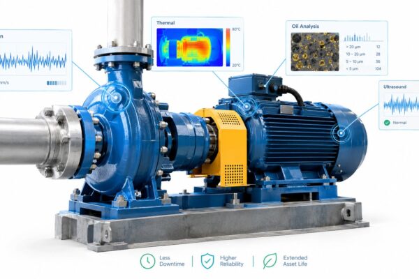
Oil analysis catches the slow story. Particle counting, wear debris, and ferrography show whether a gearbox is shedding material, running dirty, or losing its protective film. That makes it useful for abrasive wear and for confirming whether a surface problem is getting worse, even when vibration is still quiet.
Thermography and SCADA temperature trending help when surface distress is developing, especially pitting and scuffing. They do not replace vibration for crack-sensitive conditions, but they do give a useful load and lubrication clue when heat is climbing. Ultrasound adds value for lubrication state, early leakage, and some developing contact issues, especially when a route needs a fast screening check.
A practical way to sort the tools is direct.
- Vibration: strongest for mesh distress, misalignment, high-speed surface damage.
- Oil analysis: strongest for wear progression, contamination, debris confirmation.
- Thermography: strongest for heat rise linked to surface distress or lubrication shortfall.
- Ultrasound: strongest for early friction and lubrication-related changes.
Plant teams often want one monitor that finds everything. That expectation fails in service. Gear failure modes overlap, and the first useful clue changes with duty cycle, speed, load spikes, and whether the root problem is lubrication, alignment, or a tooth that was flawed from the start. For teams clarifying terminology around load response and dynamic loading, the Force Torque Sensing glossary helps connect mechanical load behavior to what the sensors are seeing.
When the question is whether a route-based setup is enough or whether the gearbox needs continuous coverage, the vibration analysis tools review is the better place to start.
A Simple Tool-to-Defect Match
| Gear Failure Mode | Best Detection Modality | Bandwidth or Sampling Need | Earliest Practical Detection |
|---|---|---|---|
| Surface distress on high-speed stages | Vibration analysis | Sensor bandwidth above 10 kHz | Early macropitting, scuffing |
| Lubricant degradation and wear | Oil analysis | Routine sampling and trending | Slow-progressing wear and contamination |
| Heat rise from surface distress | Thermography or temperature trending | Continuous or frequent trending | Pitting, scuffing, lubrication shortfall |
| Friction changes and lubrication state | Ultrasound | Route or portable screening | Early lubrication and contact change |
How the Same Gear Failure Plays Out Across Industries
A cement-kiln gearbox and a chemical plant pump-train gearbox can fail from the same broad mechanism, but the field story looks different. The difference usually comes from contamination exposure, operating duty, and how quickly the team reacts to the first clue.
Cement Kiln Gearbox
A kiln drive in a dusty environment often starts with contamination. Fine abrasive particles make their way into the oil, the flank finish degrades, and micropitting begins. Once the surface starts to break down, the distress can progress into macropitting and then into tooth fracture if the load stays on and the damage spreads. That sequence is especially painful because the early stage looks minor until the surface damage starts changing the tooth geometry.
The common mistake is to treat the visible damage as a one-off gear problem and swap parts without fixing the contamination path. The corrective action that works is usually more disciplined, seal control, oil cleanliness control, and a tighter inspection routine on the gearbox housing and breather path. In a kiln application, that is often the difference between a controlled shutdown and a repeat breakdown.
Chemical Plant Pump-Train Gearbox
A pump-train gearbox in a chemical facility can fail differently. If the lubrication system is upset, scuffing can appear first because the flank loses separation film under load. If operators then increase load to keep throughput up, the tooth sees higher stress and bending fatigue can follow. The failure becomes a mixed case, not because the metal changed, but because the operating response changed the loading path.
The common mistake here is to focus on the gear teeth after the fact while ignoring the process decision that increased load. The fix is not just a rebuild. It is restoring lubricant delivery, verifying the operating envelope, and making sure operations understands what happens when throughput is forced through a compromised drivetrain.
Gearboxes in harsh industries fail fastest when maintenance and operations solve different problems. The repair succeeds when both groups agree on the load, the oil, and the duty pattern.
For a wider rotating-equipment context, the gearbox in wind turbine topic is useful because it shows how high-speed stages make early surface distress harder to ignore once monitoring is tuned correctly.
Choosing the Right Monitoring Strategy for Critical Gearboxes
A gearbox can look healthy on a route round and still be on the edge of failure. I have seen units that stayed quiet on periodic checks, then tore themselves apart after a lubrication upset, a transient overload, or a material defect that only showed up once several stressors lined up on the same tooth. The monitoring strategy has to account for that field reality.
Use Criticality, Not Habit
Route-based vibration still works well for many gearboxes, but critical assets should not all sit in the same inspection bucket. A non-redundant gearbox on a production bottleneck, a safety-sensitive drive, or a unit with expensive restart consequences deserves more attention than a monthly walkdown. The question is whether the monitoring method matches the consequence of missing the first sign of damage.
Criticality should drive the choice. If a gearbox sits on a parallel-stage drivetrain with meaningful downtime exposure, and if bearing and gear distress tend to cluster in the same section, route checks alone may be too slow. For those assets, continuous monitoring, oil analysis, and temperature trending can catch a defect before the shutdown report does.
What to Match to the Asset
A practical decision set looks like this.
| Gear Failure Mode | Best Detection Modality | Bandwidth or Sampling Need | Earliest Practical Detection |
|---|---|---|---|
| High-speed macropitting | Continuous vibration | Sensor bandwidth above 10 kHz | Early surface distress |
| Scuffing from lubrication upset | Vibration plus temperature trending | Frequent trending or continuous coverage | Early heat and mesh change |
| Wear from contamination | Oil analysis | Routine trending | Particle growth and debris change |
| Mixed damage on critical drives | Hybrid monitoring | Combined sampling paths | Earlier than one modality alone |
The table only works if the failure mode is treated as a working hypothesis, not a label. In field cases, subsurface inclusions, poor heat treatment, grinding burn, lubrication shortfall, and transient overload can all appear in the same failure story. That is why a monitoring plan should be built to see more than one symptom at a time, especially on gearboxes that cannot afford a missed call. The root cause failure analysis approach matters here because the alarm stream has to feed a real investigation path, not just a maintenance report. Forge Reliability is one option that combines vibration, oil analysis, thermography, and reliability consulting for critical rotating assets, which is relevant when the gearbox has enough risk to justify a hybrid approach. In the same spirit, the guidance behind Intech Corporation gear durability reflects the practical point that durability depends on the whole operating picture, not one isolated test result.
Building a Mitigation Plan That Prevents Repeat Failures
A mitigation plan only works when it closes the loop from inspection to root cause to prevention. If a plant swaps a gear and never records why the old one failed, the same driver can return under a new part number. Cement kilns, pump trains, and conveyor drives all punish that kind of short memory.
The best plans start at the gearbox, but they do not stop at the tooth surface. A field failure often blends lubrication breakdown, transient overload, and a metallurgical flaw on the same member, so the first job is to separate what can be seen from what must be proven. That is the practical value of root cause failure analysis, it keeps the alarm stream tied to an investigation path instead of a loose maintenance note.
What the Inspection Sequence Should Look Like
Start with magnetic particle inspection to look for surface cracks. Check the tooth contact pattern under load or unloaded conditions, because the contact patch often shows alignment and load distribution before other tests do. Then verify surface hardness and roughness where needed, because a tooth that looks fine visually may still have a material or heat-treatment issue underneath.
Only after that should the team move to deeper metallurgical work such as microhardness surveys, microstructural etching, grain-size checks, and SEM fracture-surface microscopy. That order helps separate lubrication-related distress from material quality problems and avoids the common mistake of starting with destructive testing before the non-destructive clues are collected. Machinery Lubrication's gear-failure guidance makes the same practical point, inspection should begin with non-destructive checks before moving to harder metallurgical methods (gear failure inspection workflow).
The Control Points That Stop Recurrence
A durable mitigation plan usually rests on five controls.
- Inspection cadence. Set a schedule that reflects criticality, not just calendar habit.
- Lubrication discipline. Keep oil clean, verify the supply path, and track contamination.
- Alignment protocol. Confirm both static and dynamic alignment after assembly or repair.
- Load management. Make sure operations knows which changes increase tooth stress.
- Documentation. Record the defect, the primary mode, the likely root causes, and the corrective action.
That discipline matters even more when the failure mode is mixed. A rail-transit gearbox case with slag inclusions, heat-treatment issues, grinding burn, and insufficient lubrication shows how one surface symptom can hide several upstream causes at once. The same pattern shows up in refinery pump trains and cement mills, because the visible distress often appears long before the root cause is obvious.
For teams that need a durability reference point while designing prevention steps, the Intech Corporation gear durability discussion is a useful industry resource because it reinforces how design, material behavior, and operating discipline all contribute to life. It is a good reminder that the right fix depends on the full operating picture, not one isolated test result.
Your Next Step Toward Gearbox Reliability
The next walkdown should answer four questions fast. Is the monitoring setup capable of seeing the defect class that matters, especially on high-speed and intermediate-speed stages? Is lubricant cleanliness being checked with enough discipline to catch contamination before wear accelerates? Is the gearbox ranked correctly for criticality, or is it still being treated like a routine asset? And does the repair record point to a real root-cause process, not just a parts swap?
If the answer to any of those is unclear, the plant is still exposed. Gear failure modes are usually multi-causal in the field, which means a single fix rarely holds unless the investigation is structured. Apollo-style analysis, 5-Why, or fault tree analysis gives the team a better path than guesswork, especially after mixed failures with fatigue, lubrication, and loading all involved.
Forge Reliability offers a no-cost reliability assessment with a 24-hour response, and its plant-floor specialists work on predictive maintenance, condition monitoring, and root-cause failure analysis for gearboxes and other rotating assets. That kind of review is useful when the goal is to benchmark current gear health against documented outcomes and decide where monitoring, lubrication, or inspection discipline needs to change first.
If gearbox downtime is still showing up as a surprise, schedule a no-cost reliability assessment with Forge Reliability and have a plant-floor specialist review the gear train, monitoring coverage, and lubrication controls against the failure modes that drive repeat breakdowns.