A plant team usually notices load problems late. The first clue is often a hot bearing housing, a motor with rising axial vibration, or a pump that starts eating bearings after a process change that looked minor on paper. By then, the question isn't what radial vs axial load means. The question is why a bearing that looked acceptable in the storeroom doesn't survive in service.
That's where most guidance falls short. Definitions are easy. Reliable operation is harder. What matters on the plant floor is how load direction changes contact stress, what failure pattern that creates, which condition monitoring method sees it first, and what maintenance decision fixes it. In a gearbox, a compressor, or a centrifugal pump, the wrong call on load can turn a routine bearing replacement into a recurring downtime event.
Table of Contents
- Defining Radial and Axial Loads
- How Loads Impact Bearing Life and Failure Modes
- Diagnostic Signatures for Load-Related Faults
- Calculating and Estimating Load Components
- Bearing Selection and Mounting Implications
- Load Management in Key Industrial Applications
- Troubleshooting and Maintenance Actions
Defining Radial and Axial Loads
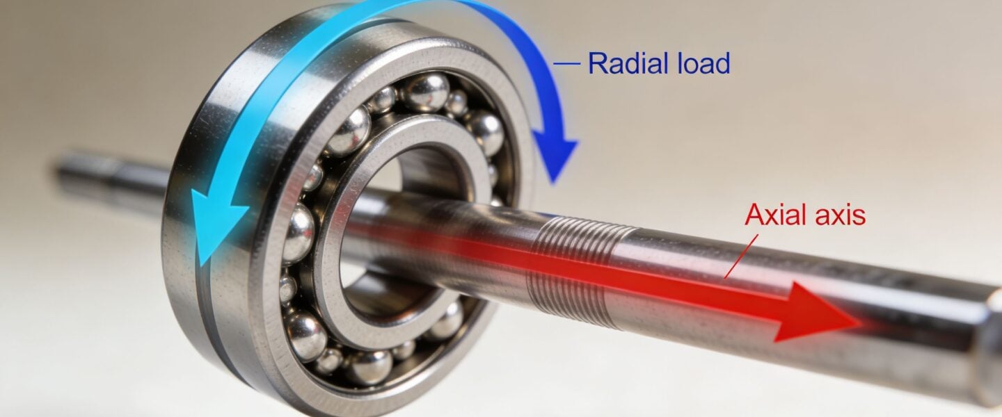
A rotating shaft only sees force in a few basic directions, but those directions change everything. Radial load acts perpendicular to the shaft centerline. Axial load, also called thrust load, acts parallel to the shaft centerline.
On a horizontal motor, the rotor weight pushing down on the bearings is a radial load. On a pump, the force trying to push the shaft lengthwise because of hydraulic imbalance is axial load. Same shaft. Different force direction. Different bearing response.
Thinking in shaft directions
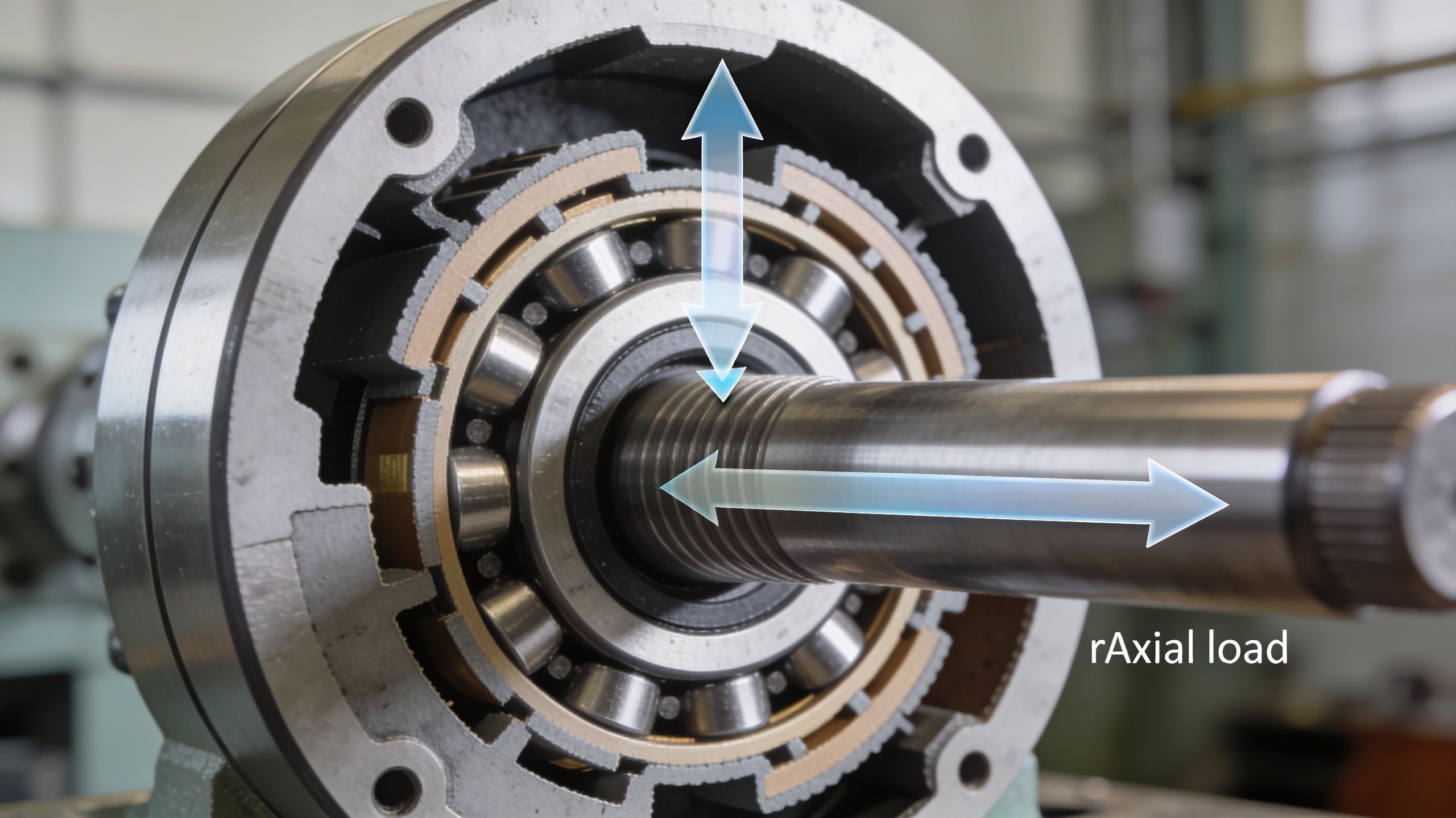
A practical way to visualize radial vs axial load is to look at the shaft as a line through the machine.
- Radial load: Pushes into the shaft from the side. Gravity, belt pull, gear mesh force, and rotor unbalance often create it.
- Axial load: Pushes or pulls along the shaft length. Helical gears, pump impellers, screw compressors, and thermal growth can create it.
- Combined load: Most real machines see both at the same time, which is why bearing selection gets tricky.
For a new plant engineer, the easiest mistake is assuming load is just “bearing load.” It isn't. Direction matters because the bearing geometry doesn't support every direction equally.
Why direction changes the bearing decision
Standard rolling element bearings usually carry radial load more effectively than axial load because of how the rolling elements contact the raceway. Bearing system fundamentals in rotating equipment matter here because the load path through the shaft, housing, and bearing seats determines whether the bearing uses its strongest contact zone or its weakest one.
A conveyor head pulley is a simple example. Belt tension creates a strong radial component on the shaft. If the pulley is also misaligned or the shaft moves axially because of thermal growth, the bearing may start seeing combined loading it wasn't selected to handle. The machine still turns, but the contact pattern inside the bearing changes immediately.
Radial vs axial load isn't a vocabulary issue. It's a load path issue.
That's the practical starting point. Before selecting a bearing, analyzing a failure, or setting alarm limits, the team needs to know which direction the machine is really pushing on the rolling elements.
How Loads Impact Bearing Life and Failure Modes
A bearing can survive years under a steady radial load and still fail early when a modest thrust load shows up after a process change, coupling shift, or thermal movement. That is why repeat failures often trace back to load direction, not just load magnitude.
Quick comparison for failure analysis
| Load factor | Radial load | Axial load |
|---|---|---|
| Force direction | Perpendicular to shaft | Parallel to shaft |
| Typical plant sources | Rotor weight, belt pull, gear mesh, imbalance | Impeller thrust, helical gears, screw compression, thermal movement |
| Contact pattern in standard ball bearings | Broader raceway engagement | More concentrated contact on one side |
| Common damage when overloaded | Fatigue, spalling, localized overstress | Ball skidding, cage damage, raceway scoring, overheating |
| Diagnostic clue | Higher response in radial measurements, load-zone wear, running-speed issues tied to support conditions | Higher axial response, thrust-related temperature rise, axial wear pattern |
| Maintenance risk if misread | Replacing bearings without fixing support or alignment | Replacing bearings without correcting thrust source or bearing type |
Why load direction changes bearing life so quickly
Bearing life is highly sensitive to equivalent dynamic load. For rolling bearings, the standard life relationship used in industry is the ISO 281 basic rating life model. In simplified form for ball bearings, life falls with the cube of the load ratio, so a relatively small increase in effective load can produce a large drop in calculated life.
The practical lesson is simple. A bearing that looks acceptable on a nameplate load basis can still lose life fast if the actual machine load shifts into a direction the bearing does not handle well.
That is what makes combined loading expensive.
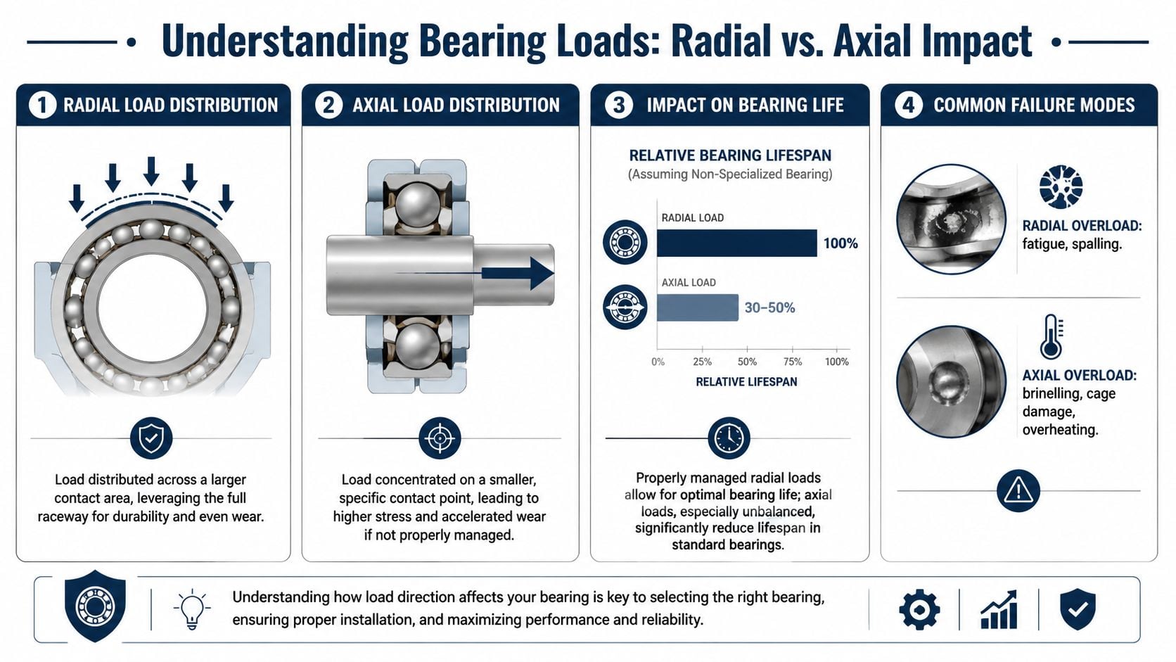
In a standard deep groove ball bearing, radial load usually spreads contact through the loaded zone more favorably than thrust does. As axial load rises, contact angle effects change, stress becomes less forgiving, lubricant film can be harder to maintain, and rolling motion is more likely to become sliding in spots. In the field, that shows up as heat, smearing, cage distress, and raceway damage long before anyone talks about formulas.
What overloaded bearings actually look like
Radial overload usually leaves a clear loaded-zone story. On belt-driven motors, fans, and conveyors, I expect to see fatigue damage or spalling concentrated where the bearing carries the steady external pull. If the lower half of the raceway is distressed and the support structure shows signs of soft foot, pipe strain, or over-tensioned belts, the bearing failure is often a machine loading problem wearing a bearing label.
Axial overload leaves a different fingerprint. Pumps, gearboxes, and screw machines often show smearing, scoring, cage wear, and discoloration from heat when thrust exceeds what the arrangement can control. Teams often call that a lubrication failure first. Sometimes lubrication is part of it, but the better question is why the rolling elements started sliding and overheating in the first place.
Thus, failure analysis becomes useful to operations. Damage location, wear pattern, temperature history, and vibration direction can tell you whether to change grease, reset alignment, reduce belt tension, inspect thrust balance, or replace the bearing arrangement entirely. A bearing teardown without that load context usually leads to another outage.
Practical rule: If a deep groove ball bearing keeps failing in equipment with measurable thrust, review the load path and bearing arrangement before ordering the same replacement again.
For teams working recurring failures, better bearing selection and installation practices for maximum life start with the same question reliability engineers ask on bad actors: what radial load, what axial load, and what changed in the machine when the failure rate went up?
Diagnostic Signatures for Load-Related Faults
A machine can run for months with the wrong load path and still avoid a hard failure. The warning usually shows up first in condition data. Teams miss it when they review vibration, oil, and temperature as separate symptoms instead of one load story.

Vibration patterns that point to load direction
Start with measurement direction. If the load problem is mainly radial, the first useful change usually appears in the horizontal or vertical readings, depending on machine construction and support stiffness. Common drivers include imbalance, belt pull, eccentric sheaves, bent shafts, and pipe strain that pushes the shaft sideways into the bearing load zone.
Axial problems show up differently. High 1x in the axial direction is one of the more useful field clues, especially on pumps, compressors, gearboxes, and coupled machines where thrust changes with process conditions. That does not prove a thrust bearing defect by itself. It does tell the engineer to check alignment, coupling condition, process pressure changes, rotor position, and whether the bearing arrangement is suited for the thrust it is seeing.
Speed matters. A machine that looks acceptable at one steady operating point can move into a harmful thrust condition during startup, low-speed operation, ramping, or process transitions. Variable-speed equipment deserves directional data at several operating states, not one snapshot from full speed.
Oil analysis and wear clues
Oil results become more useful when they are tied to likely contact behavior. Radial overload often leaves evidence of repeated stress in one loaded zone. Axial overload more often produces signs of sliding contact, scoring, smearing, fine metallic debris, and heat tinting when surfaces stop rolling cleanly and start rubbing.
The practical question is simple. Does the wear mode fit the machine's expected load path?
If a machine is supposed to carry mostly radial load but the teardown and oil condition point to thrust distress, check for alignment drift, hydraulic imbalance, thermal growth, assembly error, or a bearing arrangement that has little thrust margin. That line of thinking saves time. Otherwise the team changes grease, replaces the bearing, and puts the same failure back in service.
Load-related failures usually leave a consistent pattern across vibration direction, wear location, and temperature history. Normal fatigue usually does not show that same cause-and-effect trail.
Thermography and ultrasound for thrust problems
Thermography is a fast screening tool for friction that is building before the machine reaches alarm. A hotter housing on the thrust side after a speed or process change is worth immediate follow-up. Compare sides, compare similar machines, and compare the same machine at different loads. One thermal image by itself is rarely enough.
Ultrasound helps earlier in the sequence. It can pick up changes from skidding or surface distress before overall vibration rises enough to get attention on routine routes. That makes it useful on machines that cycle, machines with variable speed, and machines with known thrust sensitivity.
A refrigeration compressor is a good example. As pressure differential changes, thrust can move with it across the speed range. The same pattern shows up in pumps and screw machines where process changes shift the axial load without any visible change in the bearing from the outside. If the route only captures one speed and one operating condition, the data can miss the fault window entirely.
What normal versus abnormal looks like
A practical screen looks like this:
- Likely normal: Radial and axial vibration stay directionally consistent over time, housing temperatures are balanced for the machine design, and lubricant condition matches normal service.
- Possible radial overload: Radial vibration rises with machine load, temperature increases around the loaded bearing zone, and inspection points to localized stress or repeated loading in one area.
- Possible axial overload: Axial vibration becomes more prominent, thrust-side temperature runs higher, and wear evidence suggests sliding, smearing, or shifted contact patterns.
For tighter diagnosis, bearing fault detection with vibration analysis works best when the team reviews readings by direction, operating state, and process condition instead of relying on one overall number.
Calculating and Estimating Load Components
A plant engineer doesn't always need a full design package to make a useful load estimate. For troubleshooting, bearing review, or an FMEA discussion, a first-pass calculation is often enough to reveal whether the machine is operating in a reasonable range or asking the bearing to do the wrong job.
Estimating radial load from a belt drive
On a belt-driven motor, the dominant bearing load is often radial. The simplest estimate starts with belt pull acting on the shaft at the sheave. The radial bearing reaction depends on the tight-side tension, slack-side tension, sheave position between bearings, and overhung distance.
A practical field method works like this:
- Identify the drive-end sheave location relative to the nearest bearing.
- Estimate total belt pull from the tensioned belt condition or from drive data if available.
- Treat that belt pull as an external side load on the shaft.
- Resolve how much of that side load is carried by the drive-end bearing versus the opposite bearing based on shaft geometry.
If the sheave is heavily overhung, the drive-end bearing usually carries the larger share. That's why a motor on a conveyor or fan can show repeated radial-bearing distress even when the motor itself is healthy. The failure driver is the belt arrangement, not the bearing brand.
Estimating axial thrust in a pump
In a single-stage centrifugal pump, axial load often comes from pressure imbalance across the impeller. A field estimate usually starts by reviewing process conditions and the mechanical arrangement rather than trying to force precision where no design data exists.
The practical sequence is straightforward:
- Check operating pressure changes: If discharge pressure or internal clearances changed after a process modification, thrust may have changed with it.
- Review impeller and wear condition: Wear ring clearance, impeller damage, or recirculation can alter hydraulic balance.
- Assess shaft movement signs: End float, thrust-side heat, and axial vibration give clues that the calculated load case on paper no longer matches the machine in service.
Engineers don't need a perfect thrust calculation to make a good maintenance decision. They need enough evidence to decide whether the machine is seeing unexpected axial force.
A common mistake is focusing only on the replaced bearing. In pumps, the better question is whether process, internal clearances, or alignment changed the thrust load after the last outage. When that review points toward shaft movement or coupling-induced thrust, precision shaft alignment practices become part of the load calculation, not a separate task.
Bearing Selection and Mounting Implications
A bearing can be the right type on paper and still fail early in service because the load path in the machine is wrong. That shows up later as heat, axial vibration, fretting at the fits, or metal in the oil, but the problem usually started at selection or mounting.
Matching bearing type to the real load
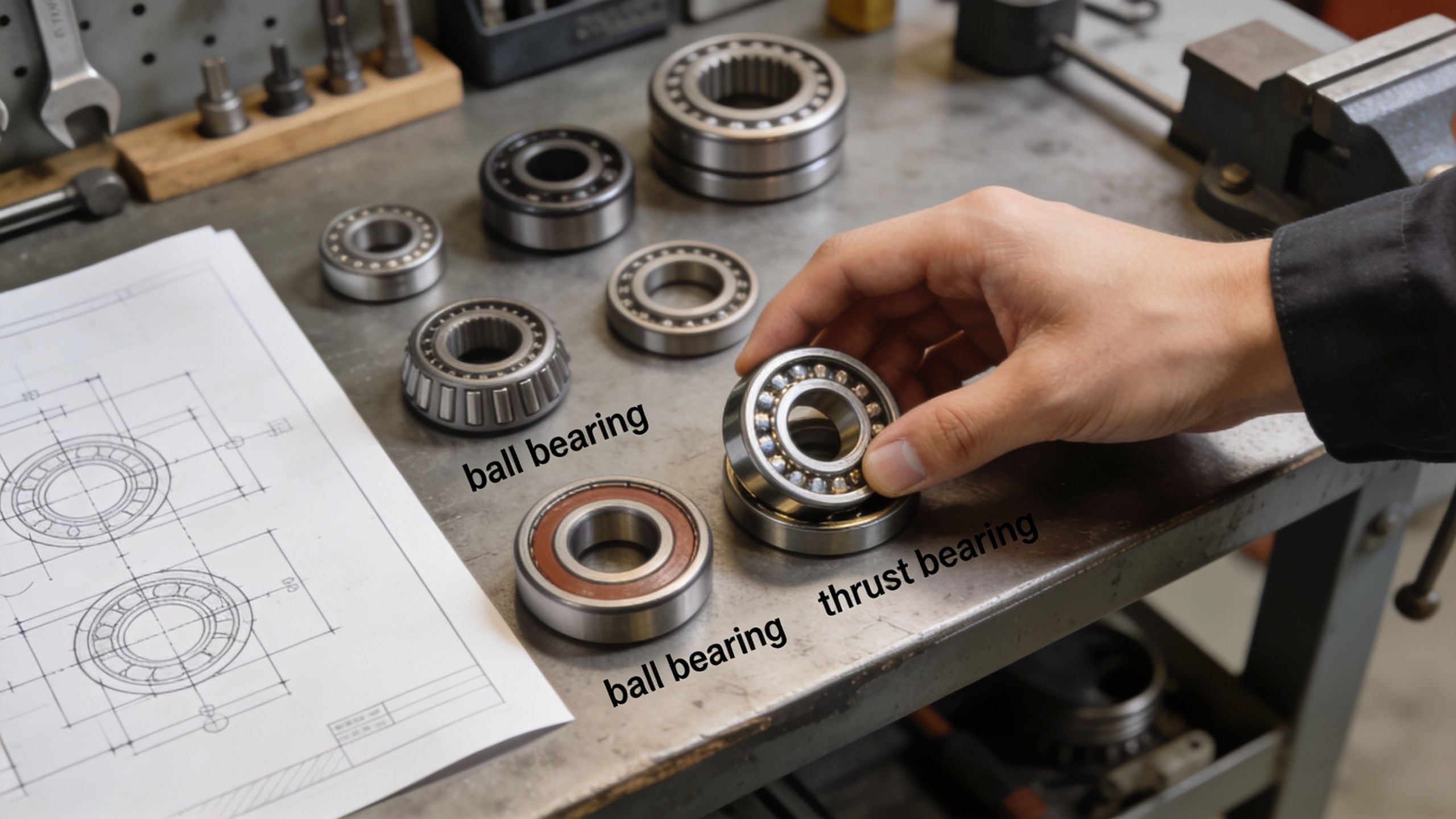
Start with the load the shaft sees, not the load everyone assumes it sees. Deep groove ball bearings fit positions where radial load carries the job and axial load stays limited or reverses direction. Cylindrical roller bearings handle high radial load well, but they are a poor choice if that same location also has to react meaningful thrust. Angular contact and tapered bearings belong in positions where combined loading is normal, predictable, and part of the design case.
The field mistake is familiar. A machine gets treated like a simple radial support problem because the shaft is horizontal and the speed looks ordinary. Then vibration shows a strong axial component, the outboard housing runs hotter than expected, or the coupling end starts showing wear patterns that point to thrust. In those cases, the bearing arrangement is telling you the load model was incomplete.
Geometry matters, but so does material. Corrosion-resistant bearing materials can solve an environmental problem and create a capacity problem if the selection team ignores the lower margin for the applied load. That trade-off may be acceptable in washdown, chemical, or wet process service, but it needs to be intentional.
Mounting arrangement changes performance
Mounting decides whether the bearing sees load the way the designer intended. The same bearing can run for years in one arrangement and fail quickly in another because fit, preload, shoulder support, and thermal growth changed the internal load distribution.
Paired angular contact bearings are a good example. Back-to-back arrangements usually give better moment stiffness and better control when the shaft sees bending plus thrust. Face-to-face arrangements tolerate some misalignment more gracefully, which can help on machines where housing accuracy or shaft deflection is harder to control.
The locating and floating arrangement is another point maintenance teams often inherit without reviewing. One position should hold axial location. The other should allow thermal movement where the design requires it. If both ends get locked by fit, mounting practice, or replacement changes, normal thermal growth turns into added thrust load. That often looks like a bearing problem even though the actual issue is the assembly strategy.
Selection mistakes that create repeat failures
Repeat bearing failures usually come from a short list of decisions:
- Using a radial-focused bearing where thrust is part of normal operation: The bearing may survive startup, then fail once the machine reaches full process load.
- Ignoring the support structure: A soft housing, worn shoulder, or damaged locknut can skew load across the rolling elements and create localized distress.
- Setting incorrect fits or preload: Too loose invites creep and fretting. Too tight raises heat and can shift the bearing into a different internal load condition.
- Replacing by part number only: If the original arrangement never handled the actual load well, installing the same bearing repeats the same failure.
These choices leave fingerprints. Axial overload often shows up as thrust-side heat, endplay changes, and vibration that shifts with process condition. Poor fit or internal preload problems are more likely to show fretting debris, ring creep, or temperature rise soon after startup. Good troubleshooting connects those signatures back to the selection and mounting decision, not just the failed component on the bench.
For plants building standard work around repairs, equipment maintenance decisions for bearing systems should tie bearing type, fits, mounting method, and expected diagnostic signatures into one job plan. That is how you stop repeat failures instead of documenting them better.
Load Management in Key Industrial Applications
A pump train runs fine for months, then operations opens a control valve, flow shifts, and the outboard bearing temperature starts climbing. Maintenance replaces the bearing. Two weeks later, the vibration is back. The problem was never the bearing alone. The load path changed, and the machine started telling you that through heat, vibration, and wear.
That is how load management shows up in a plant. The key question is not whether a machine sees radial or axial load. The key question is where that load goes, how the bearing arrangement reacts, and which condition signals appear first.
Pumps and motors on process lines
Centrifugal pumps regularly deal with both load directions. Radial force comes from hydraulic side loading on the impeller. Axial thrust comes from pressure difference across the impeller and changes with pump design, internal wear, and operating point. A pump that lives too far left or right of best efficiency point often shows that shift in bearing behavior before it shows it anywhere else.
The useful field check is to connect process changes to machine symptoms. If axial vibration rises with flow or pressure changes, and thrust-side temperature follows, investigate hydraulic thrust and internal clearances before blaming lubrication alone. If radial vibration increases after piping strain, base movement, or a coupling change, the shaft support condition may have changed enough to move load concentration across the rolling elements.
The driver matters too. Motors are often treated as radial-load machines, especially in direct-coupled service. In the field, that assumption causes missed diagnoses. Belted motors pick up radial load from belt pull. Direct-coupled motors can still show axial distress if the coupled equipment is pushing thrust back through the train, or if thermal growth changes shaft position during operation.
Review the pump and motor as one system. That cuts repeat failures.
Gearboxes in pulp and paper and bulk handling
Gearboxes rarely fail from a single clean load case. Spur and helical gear meshes create radial reactions at the shafts. Helical sets also create axial thrust that must be absorbed by the bearing arrangement, housing shoulders, shaft nuts, and the gearbox casing itself. If one part of that support chain is weak, the bearing becomes the visible failure point even when the actual problem started elsewhere.
Diagnostic discipline pays off. A gearbox with rising axial vibration, uneven housing temperatures, and wear concentrated on one side of a raceway is often dealing with thrust management problems, not just general bearing fatigue. A gearbox with strong radial vibration at gear mesh frequencies and repeated damage on overhung shafts may be carrying more bending load than the arrangement can tolerate. Oil analysis helps separate the two. Gear distress, bearing metal, and heavy debris after load changes point toward a system load problem, not a random bad bearing.
In pulp and paper, conveyors, and bulk handling, overhung sprockets, belt drives, and variable material loading can shift radial demand far enough to overload bearings that looked acceptable on paper. In those cases, the fix is usually mechanical and specific. Reduce overhang, correct shaft alignment, review gear contact, confirm housing fits, and check whether thermal growth is forcing the shafts into a different axial position than the design intended.
Compressors and turbines where axial load is critical
Compressors and turbines leave less room for guesswork. In these machines, axial load can change quickly with pressure ratio, internal clearance change, fouling, speed change, or process upsets. The first warning may be a small increase in axial vibration, a change in thrust position, or a temperature split that only appears at certain operating conditions.
That matters because axial problems escalate fast. A machine can run with moderate radial stress longer than it can run with rising thrust that is eating into internal clearance or overloading the thrust bearing. Once axial position starts moving, contact patterns inside the machine can change, seals can suffer, and damage can spread well beyond the bearing.
For variable-speed equipment, trend by operating state, not just by calendar date. Compare axial vibration, axial position, bearing temperature, and process conditions at similar loads and speeds. That is how teams catch a developing thrust problem before it becomes a trip, rotor contact event, or forced outage.
Good load management in these applications comes down to one habit. Match the machine symptom to the load direction, then check the parts of the system that create that load. That is the step that turns condition monitoring from alarm response into root-cause work.
Troubleshooting and Maintenance Actions
When a bearing issue hits the floor, the fastest path forward is a symptom-based check. Teams don't need a long theory review at that point. They need to connect machine behavior to likely load direction and take the first useful action.
Field checklist for radial vs axial load problems
High radial vibration on a motor or conveyor bearing
Possible cause: Belt pull, rotor imbalance, overhung load, or shaft support distortion.
First action: Check belt tension, inspect sheave position relative to the bearing, and review alignment and soft foot.High 1x axial vibration with rising temperature on a pump
Possible cause: Excessive thrust from hydraulic imbalance, internal wear, or coupling condition.
First action: Verify operating pressures, inspect for shaft movement, and review internal clearances at the next outage.Repeated cage damage or raceway scoring in a standard ball bearing
Possible cause: The bearing is carrying thrust it wasn't selected for.
First action: Review actual load direction during operation and confirm the bearing type matches the service.Bearing temperature split from one side of the housing to the other
Possible cause: Thrust-side friction, preload error, or axial misalignment.
First action: Compare axial and radial vibration data, then inspect mounting and axial location strategy.Gearbox bearing failures that return after replacement
Possible cause: Combined radial and axial loading with unresolved misalignment or shaft positioning error.
First action: Review gear arrangement, bearing orientation, and shaft alignment before changing bearing specification.
Good troubleshooting separates symptom from source. Replacing the bearing without correcting the load path usually buys time, not reliability.
Plants that keep seeing bearing failures in pumps, motors, compressors, gearboxes, or turbines usually don't need another generic PM checklist. They need a sharper view of load direction, failure mode, and diagnostic evidence. Forge Reliability helps industrial teams assess those problems with vibration analysis, oil analysis, thermography, ultrasound, motor current analysis, and reliability methods built for rotating equipment. Schedule a free reliability assessment to review critical assets, confirm where radial vs axial load is driving risk, and build a practical plan to reduce unplanned downtime.