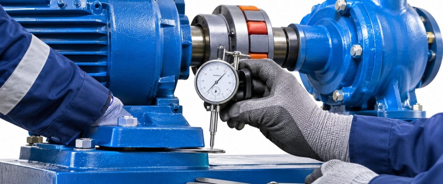
A cooling-water pump train goes back into service after a clean laser alignment. Six weeks later the 1x vibration is climbing again, the coupling element is wearing on one edge, and the outboard motor bearing runs warmer than its twin. The alignment is redone, comes in within tolerance, and the same pattern returns on the same schedule.
Nothing is wrong with the alignment technique. Something is wrong with how the machine sits on its base. When one foot rests on a burr, or a corner of a footpad has been pulled down by a hold-down bolt for years, the frame bends as the bolts come up to torque. The shaft centerline moves with it. Every reading taken in the slack state, and every alignment target calculated from those readings, describes a machine that does not exist at operating preload.
That condition is soft foot, and on a coupled motor and pump it decides whether the alignment work holds or evaporates within a few months.
Table of Contents
- What Soft Foot Does on a Coupled Train
- Limits and Foot Types to Decide the Fix
- How to Measure and Correct Soft Foot
- Field Habits That Keep Feet Stable
- Stop Shimming and Release or Escalate
What Soft Foot Does on a Coupled Train
The symptom usually arrives as a repeatability problem before anyone calls it a vibration problem. The laser head reads within tolerance with the hold-down bolts slack. Torque the bolts in sequence, take the same reading again, and the vertical offset at the coupling has moved a few hundredths of a millimeter. Re-torque and it moves again, in the same direction, by a similar amount.
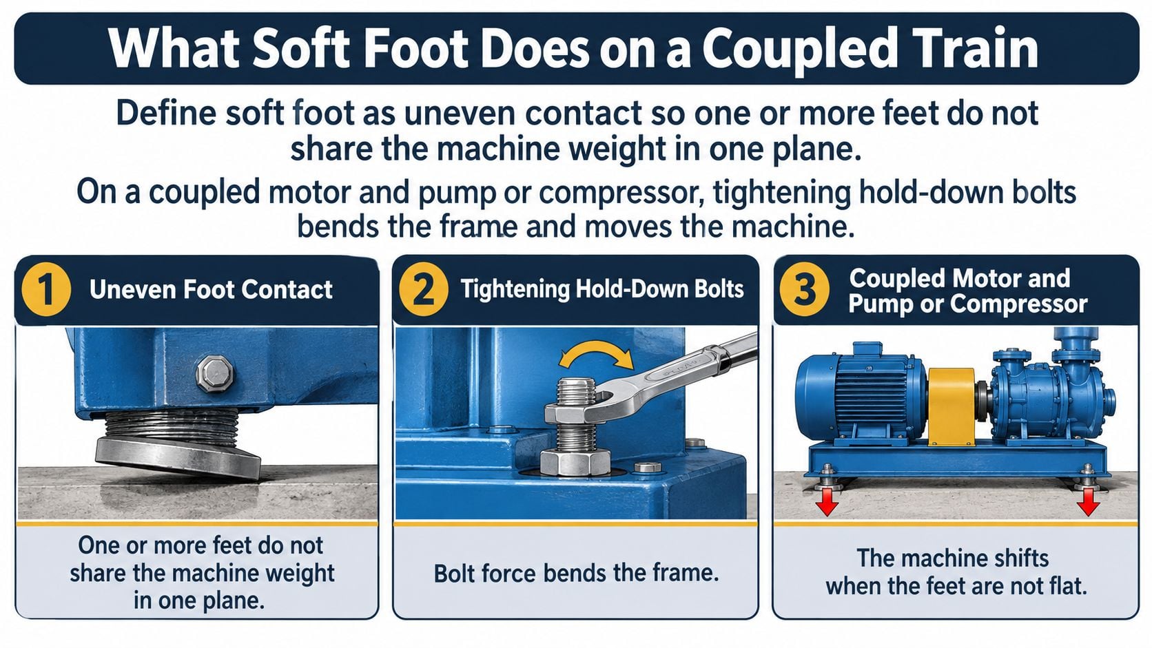
That behavior has a name. Soft foot is a foundation and mounting condition in which one or more machine feet do not sit in the same plane, or do not carry the machine's weight evenly, as the Cambridge case-history chapter on shaft misalignment and soft foot defines it. One mil is 0.001 in, so a figure like 2 mils describes a movement that is tiny by machining standards and enormous by alignment standards.
Where the distortion actually happens
A four-foot motor is a rigid body only in the drawing. Bring a hold-down bolt up to torque on a foot that sits 0.05 mm high, and the frame has to deflect to close the gap. That deflection moves the shaft centerline at the coupling, which is the reference every alignment method, dial indicator or laser, is trying to control.
On a coupled train the effect compounds. The driven machine's feet behave the same way at the other end of the coupling, so the final position of neither shaft matches the position that was aligned. This is why a clean laser reading can still hide a distorted frame: the instrument measured the loose condition accurately and reported it truthfully.
The control point is precision installation before final shaft alignment. Vibration trending tells a plant that something is wrong. It does not tell the millwright which foot is high.
The flag to work from
Loosen one bolt at a time with the others snug, put a dial indicator on that foot, and watch vertical movement. A widely used field diagnostic threshold is more than 0.05 mm, about 2 mils or 0.002 in, of movement while the bolts are loosened and retightened sequentially.
Practical rule: a machine that aligns easily with the bolts slack and fights every reading with them tight has already told you where the problem is.
Treat that as a mechanical forcing condition rather than an installation nicety. Soft foot ruins alignment repeatability, loads bearings and couplings beyond their design assumptions, and accelerates failures across motors, pumps, compressors, and gearboxes.
What the data says about the payoff
The Cambridge chapter quantifies why this deserves a mandatory hold point. After soft foot was removed and the drive train realigned to a maximum misalignment of 0.05 mm, overall RMS vibration velocity fell by factors of 2.0, 2.8, 2.2, and 3.7 at four measurement locations. A separate set of case histories in the same work reported RMS reductions ranging from 2.3 to 3.3 times after realignment and soft-foot correction.
Those are not marginal improvements in a trend line. They are the kind of change that separates a pump running to its next planned outage from one that eats a bearing every 18 months. A solid vibration analysis of motor faults can flag elevated 1x and foot-related structural peaks, which is useful for prioritizing the inspection. It cannot close the work order. The fix is mechanical, and the right first move depends on which of three foot conditions the indicator and feeler readings show.
Limits and Foot Types to Decide the Fix
An indicator reading of 0.04 mm is a number, not a diagnosis. Four mounting conditions produce that number, and only one of them is solved with a shim.
| Condition | How it shows | Test clue | First move |
|---|---|---|---|
| Parallel soft foot | Even gap under the whole foot | Feeler reading similar at three corners | One flat shim pack of the measured thickness |
| Angular soft foot | Gap on one side or corner only | Feeler changes corner to corner | Step shim, or correct the foot or soleplate |
| Squishy or induced soft foot | Indicator moves though the gap looks closed | Debris, paint, bent foot, or too many shims | Clean, deburr, and rebuild a short shim pack |
| External force | Movement returns after piping or final torque | Reading changes when pipes or neighbors are freed | Stop adding shims and investigate base or pipe strain |
What each row means in the field
Parallel soft foot is the straightforward case. The whole foot stands off its pad by a consistent amount, so a single flat pack of the measured thickness restores full contact and the correction verifies in one pass.
Angular soft foot is where most first attempts fail. The foot touches at one corner and lifts at the opposite one, so a flat pack leaves the foot supported on an edge and the bolt preload bends the frame anyway. The feeler tells the story because the reading changes from corner to corner. Correct it with a step shim, or better, dress the foot or soleplate flat.
Squishy or induced soft foot looks corrected and isn't. The gap reads closed, yet the indicator still moves when the bolt is loosened. Paint under a footpad, a burr, a bent foot flange, or a stack of six thin shims all behave this way.
External force is the row that ends the shimming conversation. If movement returns once the piping is bolted up or the neighboring machine is torqued, the foot was never the whole problem.
A reading under the acceptance line is not the same thing as a foot carrying its share of the load.
What the prevalence numbers are worth
The often-repeated figures need qualification. One industry source reports that approximately two-thirds of rotating machinery has a soft-foot problem contributing to premature asset failure, while a related poll of maintenance engineers found that 40% of respondents rarely checked for soft foot, according to the CBM Connect review of soft-foot practice. Read those as field observations rather than population statistics. Prevalence tracks equipment type, installation quality, baseplate condition, maintenance procedures, and technician training.
The same review carries a more useful finding for planning. Two highly methodical technicians completed alignment work in roughly 60% to 70% of the time required by less rigorous technicians, despite handling some of the most difficult jobs. The difference was attributed to systematic pre-alignment preparation, including checks for both parallel and angular soft foot. Thorough work is faster work when the alternative is redoing the job.
It also notes that NEMA publishes no dedicated soft-foot standard, though it specifies a 0.030 in, or 0.75 mm, tolerance for the dimension from motor shaft centerline to foot planes. That is a build dimension, not a movement limit. Many plants run with approximately 2 mils as the maximum acceptable measured movement, and that number belongs in the site precision-maintenance procedure, matched to the machine, base, coupling, and manufacturer requirements.
A pump that passed the screen and still ran rough
A documented cooling-water pump case shows why the limit is a screen and not a verdict. The unit used a 45 kW IEC 60034 motor at the Koto Panjang Hydroelectric Power Plant, and measurements at the four motor-foot locations came in at approximately 0.03 mm, 0.00 mm, 0.02 mm, and 0.04 mm, per the study of shaft alignment effects on cooling-water pump vibration.
Every foot sat under the 0.05 mm criterion the study used. The feet still did not share load equally, and the unequal support contributed to shaft misalignment. After alignment work, the reported vibration reduction included an 8.35 mm/s decrease in the highest axial vibration velocity and a 1 mm/s reduction in vertical vibration.
That is the argument for reading four numbers instead of one pass or fail.
Set the limit in the procedure, not the toolbox
Acceptance criteria belong in the plant's precision-maintenance procedure, tied to the machine, base, coupling, and OEM requirements, and cross-checked against the relevant ISO vibration standards when severity limits are used to judge the result. A crew that carries one universal number in its head will either over-shim a compressor or wave through a pump that needs correction. Write the number down, associate it with the asset class, and make the check a hold point on critical pumps, compressors, fans, and motor-driven process equipment.
How to Measure and Correct Soft Foot
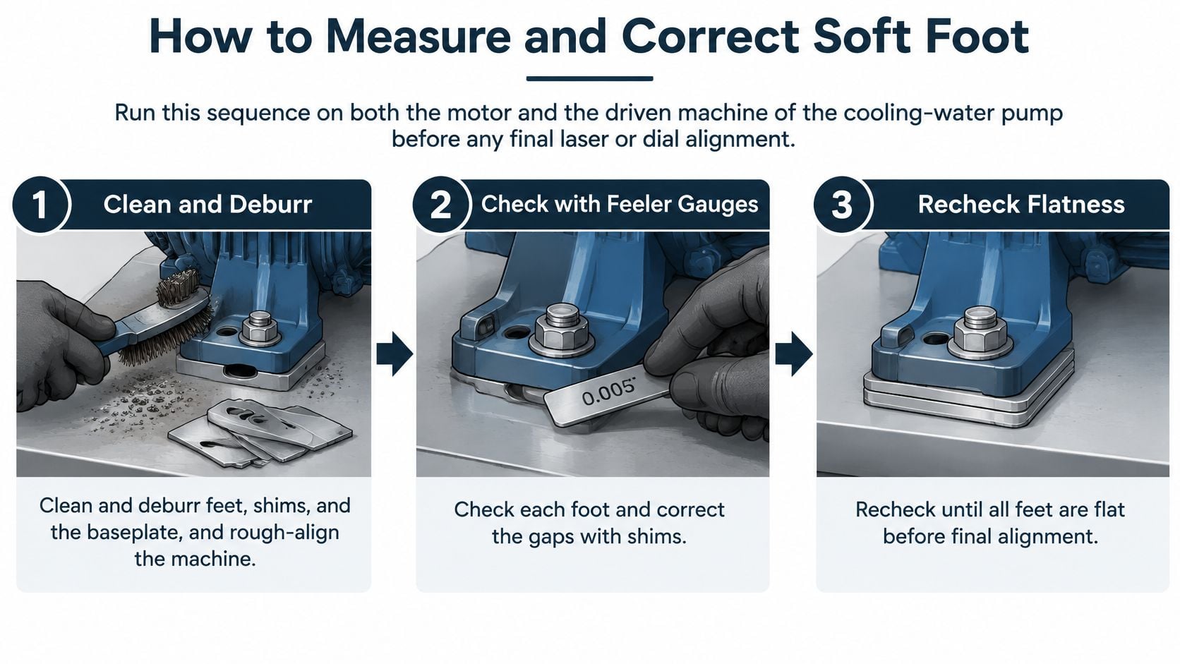
Run the sequence below on both the motor and the driven machine of that cooling-water pump train, before any final laser or dial alignment. Doing it afterward wastes the readings, because the machine moves when the bolts come up and the alignment numbers no longer describe the running condition.
The sequence, and why each step sits where it does
- Clean and deburr the feet, the shim surfaces, and the baseplate, then rough-align the machine. A burr of 0.05 mm consumes the entire acceptance budget before anyone starts measuring, and rough alignment keeps the indicator travel inside its range.
- Torque every hold-down bolt to the plant or OEM value in a cross pattern. Foot-to-foot comparisons only mean something at one consistent preload, so establish it before the first reading.
- Mount a dial indicator on the foot under test, loosen that one bolt, and record vertical movement, then repeat for each foot with the remaining bolts snug. One bolt at a time isolates the foot's contribution instead of averaging four errors together.
- Probe at least three corners of each foot with a 0.005 in feeler or shim. The pumps and systems alignment guide on soft foot recommends checking each foot at three corners, because a corner gap that never shows up at the center will survive a shim correction and re-create the problem. A feeler gauge is a calibrated strip used to determine clearance between contacting surfaces.
- Install the minimum clean, flat shim pack for a parallel gap, and a step shim only when the feeler proves an angle. The shim has to match the geometry the feeler measured, not the geometry the technician expected.
- Retorque in the same cross pattern and repeat the one-bolt check. A correction that does not survive retorque was not a correction.
- Record as-found and as-left movement for every foot with the foot ID, shim thickness added or removed, and final torque, then align and collect vibration with the bolts in the running condition. Pass or fail marks alone cannot support a root-cause review later.
Order matters more than the shims
The Acoem guide to minimizing soft foot sets the commonly cited correction threshold at 0.002 in, or 0.05 mm, of movement at any foot, tied to ANSI/ASA S2.75-2017, while some field procedures screen at 0.002 to 0.003 in before a tighter final target.
The sequence matters because checking soft foot only after shaft alignment can invalidate the alignment readings when the machine is subsequently bolted down. Pipe strain, baseplate distortion, burrs, and uneven foot geometry can also mimic or re-create soft foot, so the condition has to be rechecked after connected piping is assembled and again after final torque.
Two slips that undo a good correction
Correcting only the largest gap. A foot can appear seated at one corner and remain unsupported at the other, so the biggest number is not always the biggest problem. Chasing it leaves an angled foot open and the frame still bending.
Stacking thin shims. Every added layer is another interface, and a tall stack of thin shims reduces joint stiffness. Clean, flat shims in the fewest practical pieces hold preload better than a springy tower of 0.002 in stock.
Field note: a short, clean pack torques down and stays down. A tall stack measures well today and settles by the next outage.
What the record has to prove
The work order should carry the foot identification, the clearance or indicator movement, the shim thickness added or removed, the final bolt torque, and the repeatability of the measurement. Enter the numeric torque from the OEM or plant procedure on the work order and never estimate it on the floor, because an unrecorded value cannot be reproduced on the next alignment.
A stethoscope or an ultrasound probe can screen for uneven loading as a supporting check. Acceptance is decided only by the dial indicator and feeler readings. When the same train keeps drifting back out of tolerance, the causes behind recurring shaft misalignment run through the mounting condition first, before any coupling or bearing component.
Field Habits That Keep Feet Stable
The correction is the easy part. Keeping it stable for the next three years comes down to how the work is done and what gets written down.
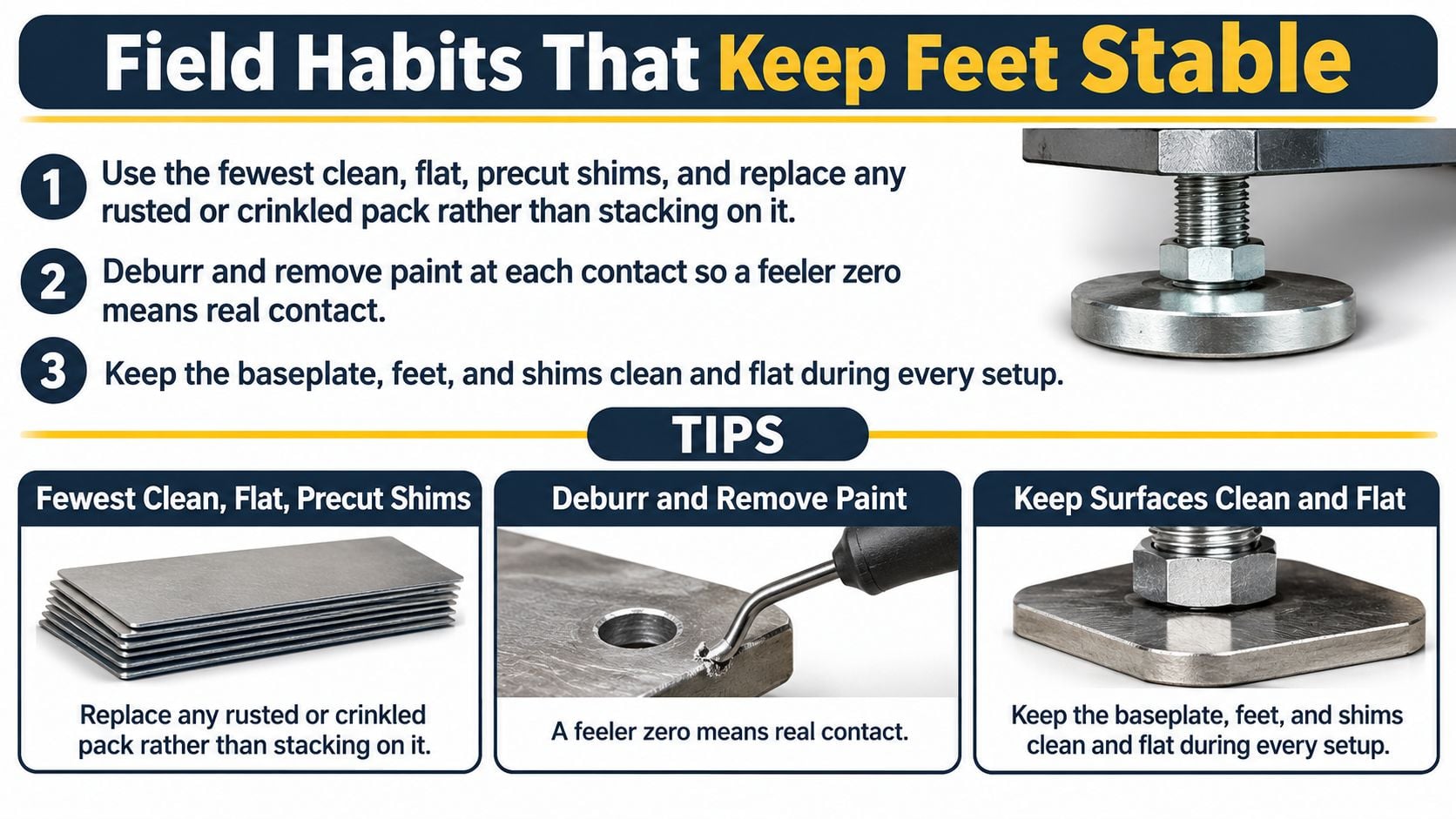
- Use the fewest clean, flat, precut shims. Replace a rusted or crinkled pack rather than stacking new shims on top of it, because a corroded layer is a future movement waiting for the next thermal cycle.
- Deburr and remove paint at every contact. A feeler zero only means real contact when the surfaces are bare and flat.
- Torque to the OEM or plant value in the same cross pattern every time, and put that number on the work order. Inconsistent preload between jobs is why two crews get two different readings from the same machine.
- Record foot ID, indicator movement, shim thickness added or removed, final torque, and repeatability. Documented numbers turn a mystery into a trend. A pass note with no as-found numbers cannot support a root-cause review two quarters later. A preventive upkeep plan for tradespeople is a practical way to keep these checks on a repeating schedule rather than waiting for a failure to prompt them.
The Cambridge induction-motor case history shows how fast corroded mounting hardware undoes a repair. A repaired motor was coupled to a pump and developed shaft misalignment because rusted shims under the motor feet and corrosion at the mounting surfaces prevented stable support. The corrective sequence was to clean the baseplate, inspect the motor base for corrosion, replace the shims, realign the drivetrain, and perform a coupled run. Overall vibration velocities fell to 3 mm/s and 5 mm/s at the drive-end and non-drive-end horizontal positions afterward, per the same motor and soft-foot case-history collection.
Recurring coupling, bearing, or seal failures should trigger an inspection of shims and mounting faces before another alignment is ordered. The one point lesson format is a useful way to capture that lesson for the next crew. Close the job with a short uncoupled vibration check, then a coupled check at the same torque used in the record.
Stop Shimming and Release or Escalate
There is a point where another shim pass stops being maintenance and becomes a way of avoiding the actual finding. That point arrives when a corrected foot moves again after final torque, when it moves after the piping is reconnected, or when the laser readings will not repeat in the bolted running state.
A measured gap does not prove that shimming is the remedy. As the Unitec review of precision coupling alignment methods puts it, excessive pipe strain, deteriorated grout, distorted soleplates, or a warped motor frame can recreate the symptom after correction. Adding a thicker pack to a dished soleplate preloads the distortion harder.
The release test
Work the cooling-water pump train in order. Loosen the connected piping and recheck foot movement. If the reading collapses, the load was coming down the pipe, so correct hangers, flange fit-up, and support condition instead of the feet. If the base rocks, the grout sounds hollow, or the soleplate is dished, escalate to baseplate repair. A warped motor frame or a corroded foot can align perfectly in the loose state and shift under preload, so a zero reading with the bolts slack proves nothing at all.
| What comes back | Likely cause | Next check |
|---|---|---|
| Foot movement changes when piping is bolted | Pipe strain | Loosen pipes and remeasure before any new shim |
| Reading returns after grout or soleplate is loaded | Deteriorated grout or distorted soleplate | Map the base and plan a base repair |
| Loose-state alignment moves at final torque | Warped frame or corroded foot | Clean surfaces and remeasure all four feet torqued |
| 1x stays high and bolts loosen in service | Soft joint or short preload | Fewer shims and a documented cross-pattern torque |
| Coupling, bearing, or seal failures repeat | Unequal foot load on driver or driven unit | Correct the larger mover first, then realign both |
Release the train only when every foot sits inside the site limit at final torque with the piping connected, the shims are recorded, and alignment and vibration have been repeated in that state. If movement returns or failures repeat, do not schedule another shim pass. Use the symptom table and the root cause failure analysis method to fix the largest mover first, then realign both machines. The same forcing shows up on compressors, fans, and gearbox-driven process machines, where the driven unit's base condition is checked just as carefully as the driver's.
Forge Reliability builds reliability programs around exactly this kind of question, using vibration analysis, precision alignment, and root cause failure analysis to determine whether soft foot is the initiating failure mode or one finding among several mounting and connected-equipment risks. Its engineers work through foot-by-foot soft-foot measurement, baseplate and shim condition, and alignment verification on pumps, compressors, motors, and gearboxes, then help plants prioritize the assets where unplanned downtime costs the most. Start with a no-cost reliability assessment by visiting Forge Reliability and putting the movement question in front of someone who can close it.