The most common advice about clamp on temperature measurement is to tighten the sensor, add insulation, and trust the reading. That's an installation shortcut, not a measurement strategy. A clean, repeatable surface reading can still be unsuitable for the alarm a maintenance team wants it to trigger.
The practical question isn't whether the sensor is accurate in isolation. It's whether the installed measurement uncertainty is small enough to distinguish a developing failure from normal operation. A gearbox oil warning, a chilled-water performance check, and a hot-oil shutdown shouldn't share the same acceptance criteria.
Table of Contents
- How Accurate Clamp-On Temperature Really Is
- Why a Pipe-Surface Reading Is Not Fluid Temperature
- Clamp-On Versus Thermowells, Immersion Probes and Thermography
- How to Install and Validate a Clamp-On Sensor
- Setting Alarm Limits by Failure Mode
- Diagnosing Drift, Lag and False Readings
- Confirm Your Measurement Plan Before Trusting an Alarm
How Accurate Clamp-On Temperature Really Is
| Pipe and fluid case | Stated accuracy | Condition behind the figure |
|---|---|---|
| Sanitary pipe, water-like fluid | ±0.5 °C | Omega HANI data, fluid thermal conductivity similar to or greater than water |
| Sanitary sensor, 0 °C to 100 °C | ±0.50 °C | Comhas sanitary sensor product data |
| Corrected system, turbulent flow | Below ±0.7 K at 2-sigma | AndaSol field study, Reynolds number above 30,000 and fluid temperatures up to 400 °C |
| Industrial pipe, water-like fluid | ±1.0 °C | Omega HANI data, fluid thermal conductivity similar to or greater than water |
| Sanitary pipe, oil or propylene glycol | ±1.0 °C | Omega HANI data, expected accuracy without user calibration |
| Industrial pipe, oil or propylene glycol | ±1.5 °C | Omega HANI data, expected accuracy without user calibration |
| Industrial plastic pipe | Approximately ±1.5 °C | Omega plastic-pipe sensor specifications; pipe tolerances, surface finish, and coatings affect accuracy |
| Conventional insulated surface sensor | At least 10% error | Omega HANI data, reported baseline relative to actual fluid temperature |
| Two-clamp non-invasive sensor, ABB | No accuracy figure published | Installation capability alone does not establish accuracy; request application-specific performance documentation |
Reading guide: Each figure holds under the conditions stated in its row: fluid conductivity, pipe construction, flow regime, and calibration state. Percentage error, absolute accuracy in degrees, and a 2-sigma statistical bound each describe a different quantity, so they are comparable only after their definitions are checked.
What the specification covers
Thermal conductivity describes how readily a material transfers heat. A fluid that moves heat readily into the pipe wall presents a different measurement problem from an oil circuit, where the wall-to-fluid temperature difference carries more weight.
Pipe construction matters just as much. A sanitary metal tube, a thick industrial pipe, and a plastic line give the sensing element three different heat paths. A more precise sensing element cannot fix poor contact geometry or an unrepresentative location, and the table's figures assume the stated pipe and fluid. A line that departs from those conditions departs from the stated accuracy with them.
The corrected solar-thermal result needs particular care. Reynolds number is a dimensionless measure used to characterize flow behavior; the stated result applies to a specified turbulent-flow regime. Kelvin, abbreviated K, expresses temperature differences of the same size as degrees Celsius, while 2-sigma identifies the statistical confidence convention used for the reported uncertainty.
Judge accuracy against the warning margin
Accuracy earns its keep only against a specific failure mode. Take a gearbox lubrication circuit where maintenance wants early warning before oil temperature reaches an intervention limit. When the gap between a healthy reading and that warning is narrow, a healthy condition and a developing fault sit inside the same error band, and the sensor cannot separate them.
The same logic assigns each failure mode its own budget. A hot-oil shutdown with a wide margin tolerates a larger installed error. An oil or glycol line already quoted at ±1.5 °C under favorable conditions resolves changes only a few times smaller than a tight warning margin demands. Set the required uncertainty per failure mode first, then check whether any clamp-on figure meets it.
A stable trend remains useful for catching change, yet decimal places on the display say nothing about installed error. The relevant comparison includes reference uncertainty, installation bias, and behavior under representative loads.
Selection rule: Identify the applicable pipe-and-fluid case, then confirm the alarm margin is wider than the installed uncertainty. If it falls short, change the measurement strategy before changing the alarm setting.
Why a Pipe-Surface Reading Is Not Fluid Temperature
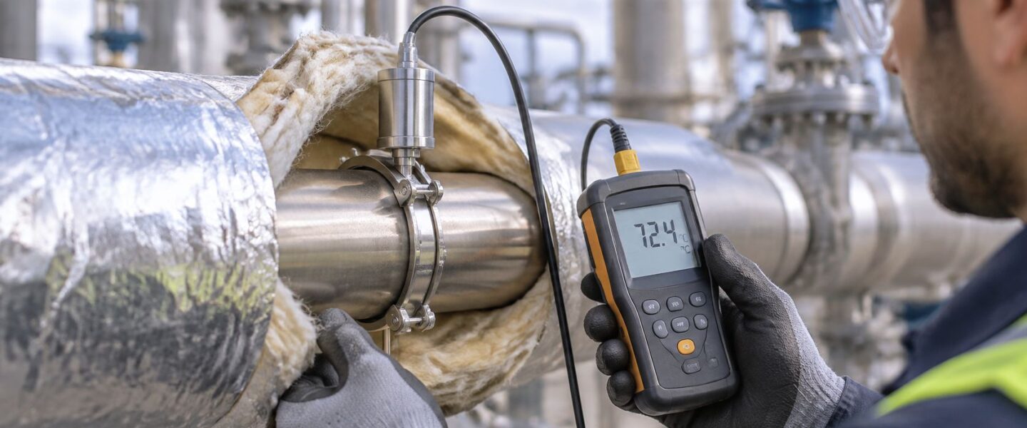
A pipe-surface sensor measures the outside of the pipe. The sensor responds to wall temperature, which is only a proxy for fluid temperature. A thermocouple, which generates an electrical signal from temperature differences, or an RTD, a resistance temperature detector, attaches externally without cutting the line, fitting a thermowell, or interrupting flow.
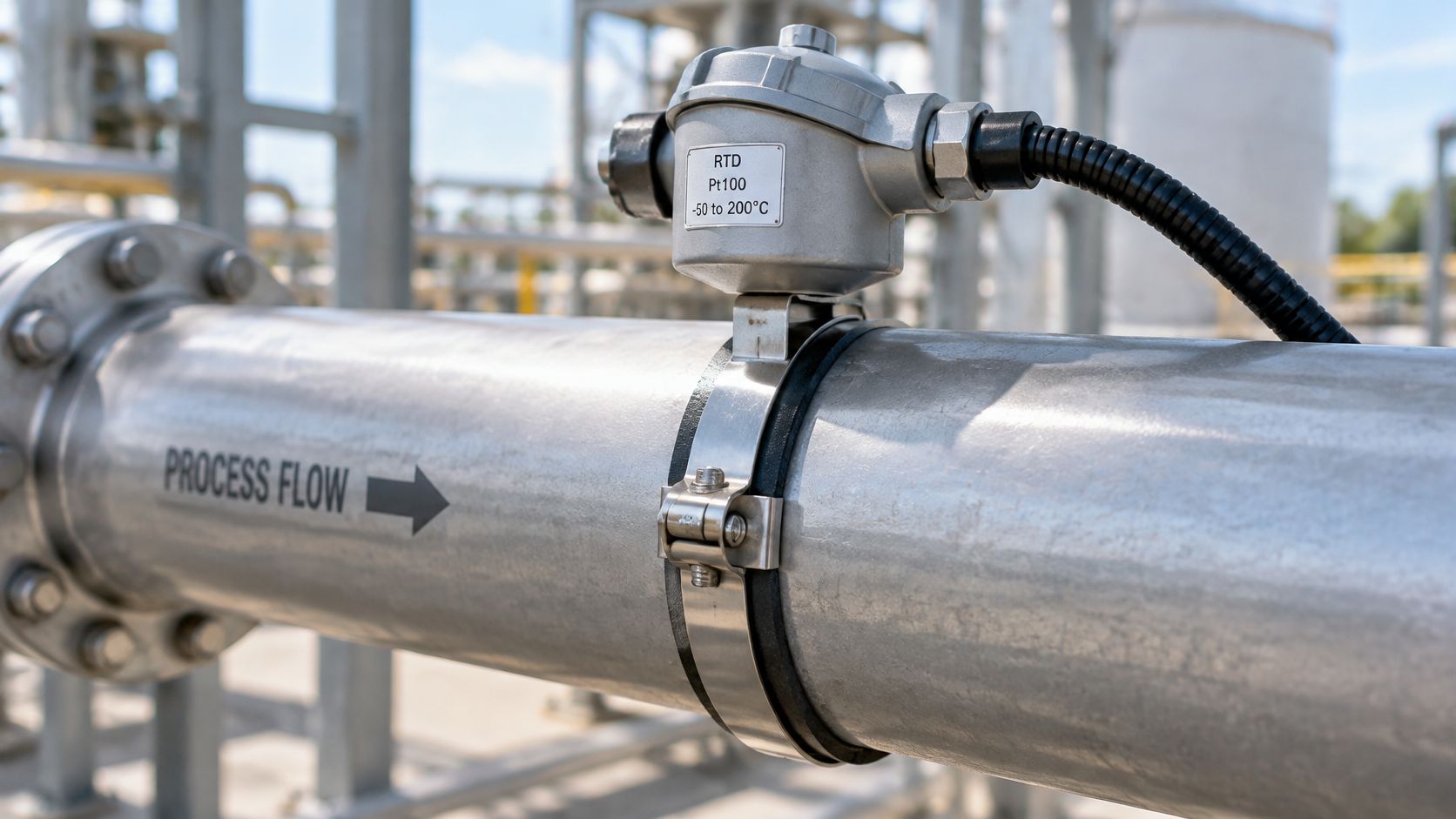
The sensing element follows heat conducted through the wall and exchanged with its surroundings. Thermal coupling, the effectiveness of heat transfer between the pipe and element, determines how closely the reading tracks the contact surface.
Air gaps and weak contact pressure interrupt that path. Coatings, wall thickness, and insulation add thermal resistance, while airflow, sunlight, and ambient swings change heat exchange on the outer surface. The ifm temperature application guide gives application-based selection guidance; the engineering distinction that matters is between a surface value and a value representative of the process.
A steady number can conceal a changing process
Stratification means fluid layers have different temperatures. Fouling means deposits have accumulated on a heat-transfer surface. Either condition can shift the relationship between the fluid inside and the wall outside while leaving the sensor itself healthy.
A condensate return line shows how this plays out. The clamp trace holds steady through a period when changing return flow alters the liquid distribution and heat transfer inside the pipe. An operator who treats that surface reading as a stand-in for an immersion RTD concludes the process is stable when only the outside of the pipe is stable.
The solar-thermal field work illustrates the same gap. Researchers applied a dimensionless correction function to compensate for the wall-to-fluid temperature difference across the collector loops. The corrected estimate came from the measurement system and its model working together; the raw wall reading alone could not supply it.
Non-invasive doesn't mean consequence-free
Skipping a pressure-boundary penetration removes a real installation hazard. The operational risk of a missed alarm or an unnecessary shutdown stays on the table.
A compensated temperature is also model-dependent. Changes to insulation, pipe construction, fluid service, or operating conditions can invalidate the assumptions behind it even when the electronics remain healthy.
Before selecting a location, the asset record should identify the objective:
- Pipe-skin protection: Detect an unacceptable temperature at the external wall.
- Equipment overheating: Identify a thermal condition associated with equipment distress.
- True process temperature: Estimate or measure the fluid condition needed for a process decision.
Each objective tolerates a different gap between wall and fluid temperature. Pipe-skin protection can tolerate a wide gap because the wall itself is the variable of interest, while a process-temperature estimate allows very little. I would size the acceptable measurement error against the specific failure mode before trusting the point. A mounting position chosen for convenience can sit far from the evidence the decision needs.
Clamp-On Versus Thermowells, Immersion Probes and Thermography
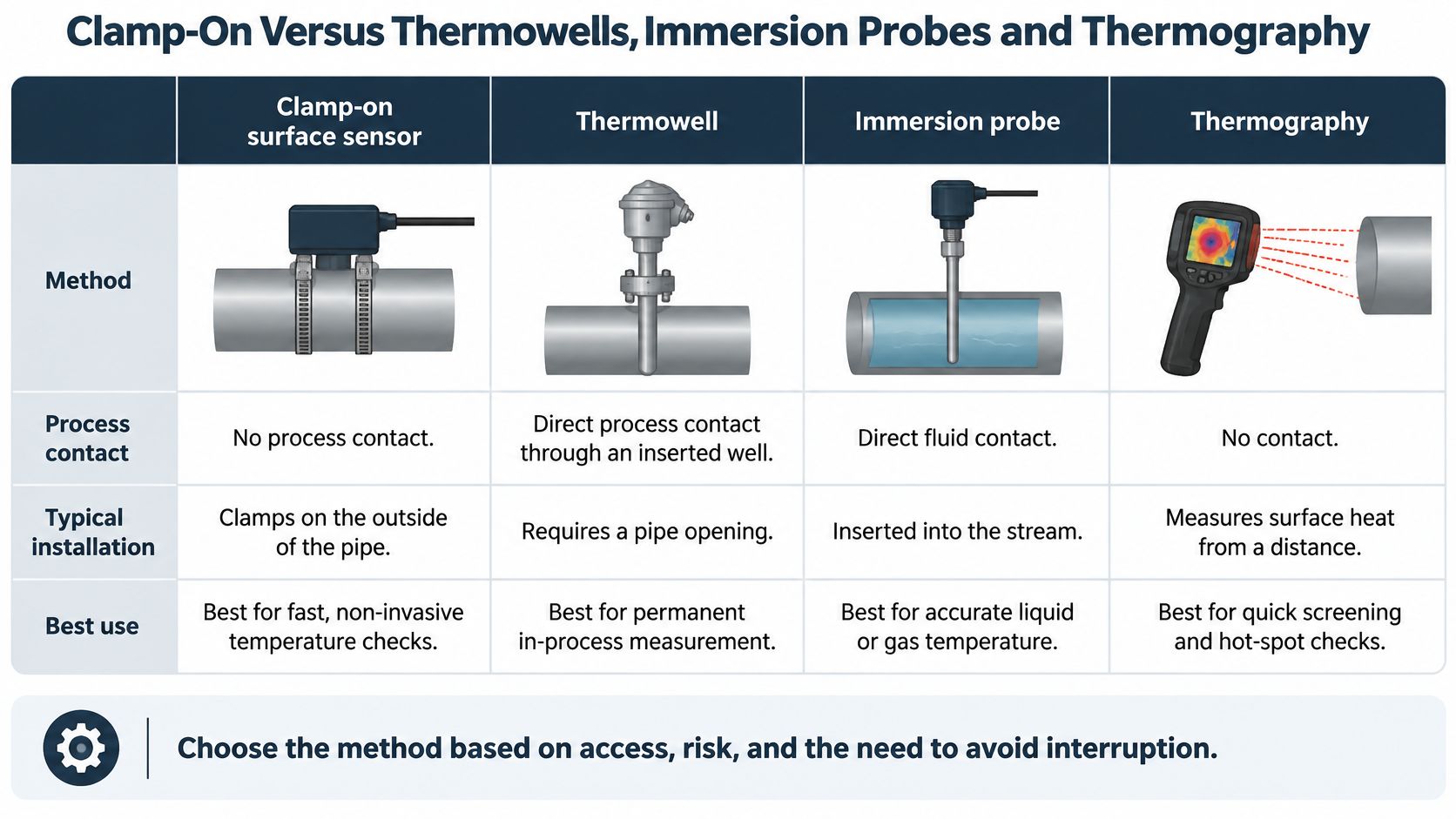
Choose the method around the decision and the consequence of being wrong. Every failure mode you protect against has a temperature excursion worth alarming on, and the method you pick has to resolve that excursion within its own uncertainty. External screening, permanent process control, and commissioning reference measurements are different jobs.
| Method | Process contact | Typical installation | Best use |
|---|---|---|---|
| Clamp-on surface sensor | None; attaches outside the pipe | Under 1 hour per point for the two-clamp system described by ABB | Trending, screening, and temporary checks |
| Thermowell with RTD | The well contacts the process; the sensor sits inside the well | Engineered pipe opening, often involving welding during an outage or a separately approved hot-tap procedure | Trips and control requiring representative fluid temperature |
| Immersion RTD in pipe | Direct fluid contact | Approved process connection with suitable insertion depth, sealing, and isolation | Commissioning reference and calibration |
| Infrared thermography | No physical contact; line of sight | Route-based inspection without a permanent fitting | Hot spots, insulation breakdown, and casing gradients |
The same ABB announcement reports installation-related savings up to 75% against thermowell-based measurement, along with support for HART 7, an industrial instrument communication protocol, and assessment against IEC 61508 SIL2, Safety Integrity Level 2. These are product-specific statements from one manufacturer, not generic properties of clamp-on sensors.
A SIL assessment does not approve a loop
SIL assessment makes a non-invasive instrument a candidate for safety-related architectures within its assessed scope. Any specific surface installation still has to demonstrate that it meets the plant's shutdown requirements.
The responsible engineer verifies the applicable safety documentation, application restrictions, diagnostic behavior, and complete loop design. A safety loop includes the sensing arrangement, logic, and final action, not just the temperature transmitter.
Thermowells also need engineering. They preserve a pressure boundary around a removable sensor, but insertion geometry, mechanical loading, and thermal response still affect performance. An intrusive fitting produces a representative reading only when that geometry is correct for the duty.
Match access to the diagnostic task
A temporary clamp-on point on a chemical oil-transfer line can answer whether a thermal trend follows load without draining or exposing the process. If that point becomes a permanent operating alarm, its validation requirements change.
For external thermal patterns, thermography inspections can identify casing gradients or damaged insulation that a single contact point would miss. Infrared measurements still concern surfaces and require attention to emissivity, a surface's effectiveness at emitting thermal radiation.
Use clamp-on measurement where its verified uncertainty stays small against the temperature rise that defines the failure mode. Retain an intrusive reference wherever the decision depends on fluid temperature that the external arrangement cannot adequately resolve.
How to Install and Validate a Clamp-On Sensor
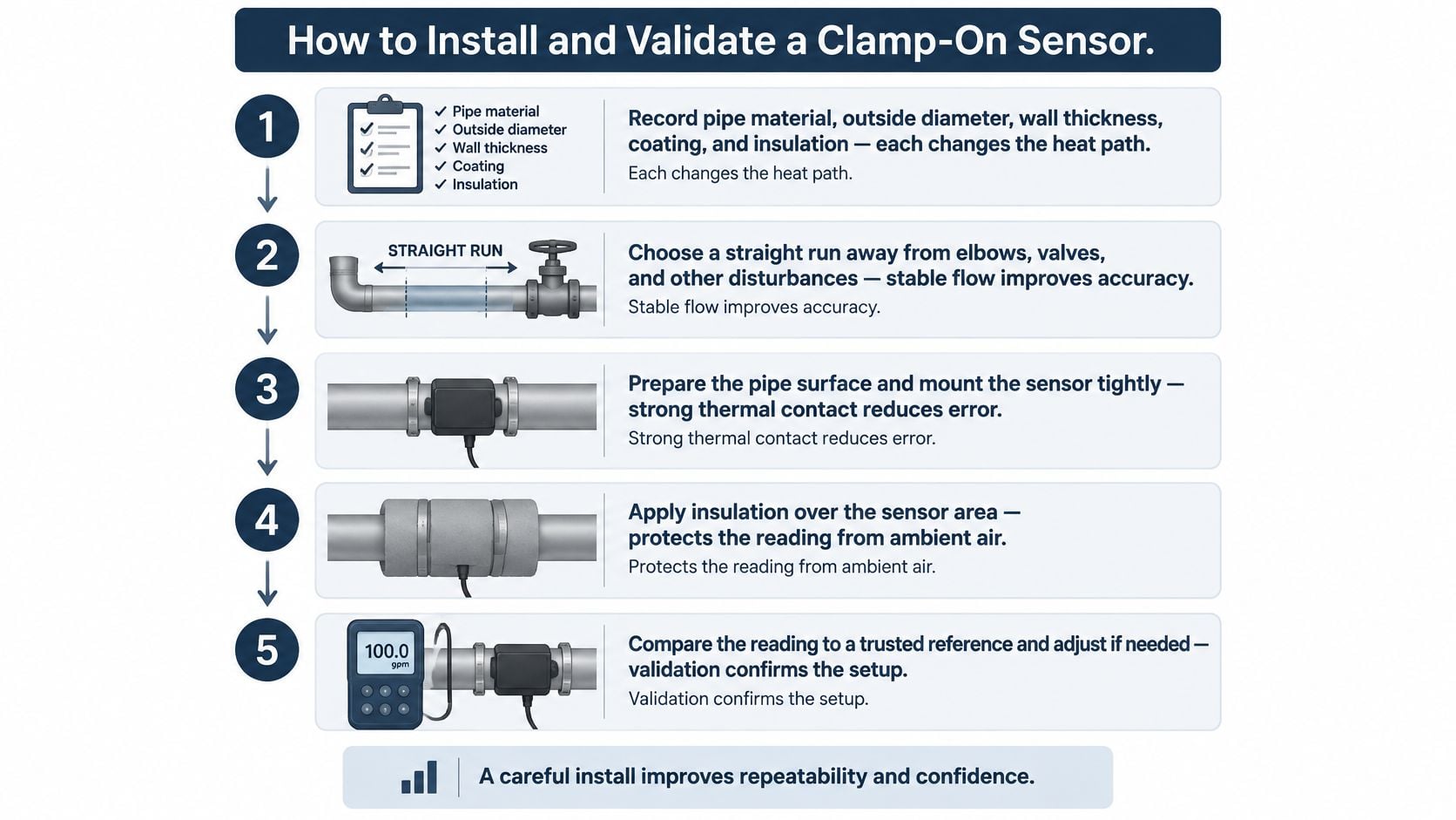
A good installation produces a repeatable heat path. Validation then establishes whether that heat path produces a measurement suitable for the intended decision.
Establish the physical installation
Record the pipe construction. Capture material, outside diameter, wall thickness, coating, and insulation in the asset record. Each affects the heat path or whether the selected clamp fits correctly.
Select a straight run away from elbows, valves, and pump discharge disturbances. The aim is stable, representative flow, not the elimination of turbulence; some compensated systems require turbulent flow to meet their stated performance.
Prepare the approved contact area. Remove loose scale and contamination, and achieve the surface condition specified for the sensor. Protective coatings shouldn't be removed without authorization, especially where they provide corrosion protection.
Apply the specified thermal interface material, which fills small contact voids, and secure the clamp with controlled, repeatable force. Excess compound or excessive tightening isn't a substitute for correct fit and can create another installation problem.
Insulate and protect the sensing area according to the approved sensor arrangement. Shielding against airflow and solar loading should preserve access and avoid creating an unapproved moisture trap beneath the insulation.
Validate the complete measurement
Log ambient temperature alongside the pipe reading and operating state. A useful commissioning record includes load, flow condition, and nearby heat sources so the engineer can distinguish a process response from environmental influence.
Compare against a trusted reference during stable operation, then observe a known process change. The reference should represent the same fluid condition, with timestamps aligned so location and transport delay aren't mistaken for sensor lag.
For surface measurements, Fluke's industrial temperature calibration guidance recommends a surface calibrator, rather than relying only on a fluid bath. Fluke also cautions that a pipe-surface reading doesn't necessarily indicate true fluid temperature and recommends internal measurement when possible.
A surface calibrator checks the sensor's response under surface-contact conditions. An installed reference comparison checks something different: whether the entire pipe, mounting, insulation, and compensation arrangement represents the process adequately.
Preserve the evidence
If the reference difference remains reproducible across the intended operating range, an in-situ calibration, meaning calibration in the installed location, may establish a useful correction. An offset that changes unpredictably with flow or ambient conditions needs investigation before correction.
The same distinction between calibration and process representativeness matters in other instrumentation, including a dissolved oxygen sensor. Passing a calibration check doesn't prove that the installed location represents the condition operators need to control.
Commissioning record: Store the reference offset, ambient conditions, operating state, mounting details, correction settings, and date with the asset. Without that baseline, the next technician can't distinguish process deterioration from a changed installation.
Setting Alarm Limits by Failure Mode
A universal temperature threshold fits no asset class. The acceptable uncertainty comes from the failure mechanism, the available warning margin, and the consequence of an incorrect decision.
| Application | Tolerance needed | Verification |
|---|---|---|
| Overtemperature trip on hot-oil or steam line | Tight; surface reading supports but doesn't replace the trip input without an approved design | Immersion reference at the operating point |
| Gearbox or hydraulic oil temperature rise | Tight; uncertainty can consume most of a small warning margin | Reference sensor at representative load |
| Sanitary or food process temperature | Tight; applicable sanitary sensor specifications must be demonstrated in service | Calibrated reference with documented records |
| Chilled-water or condenser loop | Moderate, provided uncertainty is small relative to the diagnostic temperature difference | Periodic reference check at a known load |
| Pump or motor thermal trend | Looser absolute accuracy; change from baseline may matter more | Baseline comparison with thermography |
The table gives engineering priorities, not acceptance limits. A plant's allowable error must follow the equipment requirement and alarm purpose, rather than a generic label such as tight or moderate.
For a hydraulic oil circuit, the engineer should compare the expected healthy operating range with the intervention temperature. If uncertainty leaves no reliable separation, a lower alarm setting may create nuisance work orders rather than earlier fault detection.
Separate process alarms from measurement alarms
Every clamp-on point needs distinct criteria for the process and for measurement health:
- Bias limit: Define the acceptable difference from the reference under matched conditions. A persistent offset beyond that limit triggers measurement review, not an automatic equipment diagnosis.
- Response-time limit: Define how long the installed point may take to reflect a known process change. Slow response can make an otherwise accurate reading unsuitable for a rapidly developing failure.
- Sensor-fault limit: Flag implausible flat-lining, discontinuities, communication faults, or changes inconsistent with the operating state. These require a defined fallback action.
Bias is a systematic offset. Response time describes how quickly the installed measurement follows a change. Neither should be hidden inside a single temperature alarm.
Connect the limit to the failure mechanism
A manufacturing failure mode and effects analysis can connect each measurement to the equipment failure it is intended to detect. For a pump, a rising casing temperature trend might justify checking operating point and vibration; it doesn't, by itself, prove bearing damage.
Trend alarms should consider deviation from a load-matched baseline and the rate of change, meaning how quickly temperature moves. Absolute alarms belong where uncertainty and response are known well enough to support the required action.
Before a clamp-on point generates a work order, the asset class needs its own limit set, confirmation method, and operator response. Automatic escalation without those definitions converts ambiguous measurements into maintenance demand.
Diagnosing Drift, Lag and False Readings
| Symptom | Likely cause | Fix |
|---|---|---|
| Reading lags process changes by minutes | Air gap or weak contact pressure | Clean contact area, renew interface material, and reclamp at controlled force |
| Reading stays steady while the process drifts | Moved insulation or cladding, or changed shading | Restore the intended arrangement and compare with an immersion reference |
| Reading tracks ambient temperature | Airflow or solar exposure | Shield and insulate, then compare against ambient |
| Stable offset from immersion reference | Unaccounted wall or coating effects | Apply a validated in-situ correction |
| Shift after repainting or reinsulation | Changed thermal path | Re-verify and update the record |
| Jumps without process change | Loose clamp, damaged cable, or connector | Check mechanical and electrical integrity before recalibration |
Each symptom raises the same question: is the shift larger than the uncertainty the alarm limit already assumes? A drift smaller than the alarm margin changes nothing operationally. A drift larger than what the installed sensor can resolve invalidates the limit itself.
Test before replacing
Compare the clamp and immersion reference at distinct operating points. An offset that grows with flow points to a changing wall-to-fluid relationship or a contact problem. An offset that stays constant across the range is a candidate for an in-situ correction.
A cooling-water return line that reads lower after its pipe is reclad tells the same story: the thermal path changed while the sensor stayed the same. Re-verify against the immersion reference and update the installation record before touching the instrument. Persistent discrepancies warrant root cause failure analysis, and Kagool's discussion of data-driven equipment maintenance shows how condition records support that kind of decision.
- Ambient coincidence: Treat a reading stuck at ambient on a known hot line as suspect until independently checked.
- Change history: Record every coating and insulation intervention, since each one alters the thermal path.
- Correction validity: Re-validate any in-situ correction after cladding is disturbed; the old correction described a different installation.
Recalibrate only when the offset is reproducible across operating points. Replace the sensor only when it or its connection shows a physical defect.
Confirm Your Measurement Plan Before Trusting an Alarm
A useful measurement plan can begin with an asset-record review rather than another sensor purchase. The maintenance and operations teams need agreement on what each point means and what happens when it alarms.
- Identify the objective for every candidate point: pipe-skin protection, equipment overheating, or true process temperature.
- Classify the consequence of an incorrect alarm using the application tolerance table under setting alarm limits. Include both missed faults and unnecessary intervention.
- Document the installation and uncertainty, including material, wall thickness, coating, insulation, and the basis for acceptance.
- Select the verification route: an immersion reference at operating conditions, thermography for casing gradients, or a surface-calibrator check.
- Define confirmation and fallback actions. Specify when vibration, ultrasound, or another independent measurement must support a temperature alarm, and what operators should do when confirmation isn't available.
Condition monitoring systems combine vibration, oil analysis, thermography, ultrasonics, and MCSA, motor current signature analysis, for unified equipment health surveillance. Forge Reliability assigns new monitoring tasks with defined points, thresholds, and frequencies tied to P-F intervals, the time between a detectable potential failure and functional failure, plus clear actions when thresholds are exceeded.
A clamp-on reading is only as trustworthy as its recorded uncertainty.
Forge Reliability offers a free reliability assessment to review existing temperature points, their measurement uncertainty, and their alarm margins. Visit Forge Reliability to request an assessment and identify where clamp-on monitoring is adequate, where reference checks are needed, and which alarms require a different measurement approach.