A line freezes, production slows, and the first reaction is usually to blame the heating cable. In many plants, that's the wrong starting point. The circuit may be intact while the controller is misapplied, badly commissioned, reading the wrong sensor value, or tripping on a wiring problem that looks like a heater failure.
That's why a heat tracing controller deserves attention as a reliability device, not just an accessory. The plant team that treats it as a simple thermostat usually ends up chasing nuisance alarms, replacing healthy cable, or discovering too late that a “protected” line had no effective control strategy behind it.
Table of Contents
- The Role of the Heat Tracing Controller in Plant Reliability
- Control Methods and Controller Types A Practical Comparison
- Key Selection Criteria for Industrial Applications
- Installation and Commissioning to Prevent Future Failures
- A Reliability Engineers Guide to Troubleshooting Failures
- Integrating Controllers for Predictive Maintenance and SCADA
- Your Actionable Heat Tracing Controller Maintenance Checklist
The Role of the Heat Tracing Controller in Plant Reliability
A refinery transfer line, a water treatment chemical feed line, or a food plant syrup header can all fail the same way. The pipe has heat trace installed, the breaker is on, and the process still loses temperature. In many of those cases, the problem isn't “no heat trace.” The problem is poor control, poor visibility, or no meaningful alarming.
The control layer matters more now because electric heat tracing is being used across more assets and more industries. The global electric heat tracing market was estimated at USD 2.96 billion in 2024 and is projected to reach USD 4.34 billion by 2029, with a stated 7.9% CAGR, according to electric heat tracing market projections from MarketsandMarkets. As installed tracing capacity grows, controller reliability becomes more important because every added circuit creates another point where a bad setpoint, failed sensor, or missed alarm can cause a process upset.
A basic thermostat can switch a circuit on and off. A true heat tracing controller does much more than that. It manages temperature, monitors current and voltage behavior, and gives maintenance teams alarms that point toward the actual failure mode before the line freezes or the product quality drifts.
Why the controller is the reliability pivot
A useful comparison is this. A simple thermostat is closer to cruise control. It reacts to one variable and does one thing. A modern controller acts more like the system that supervises the whole operating condition. That difference matters on long pipe racks, outdoor tanks, and process lines where the plant team can't rely on occasional walkdowns.
For industrial facilities that also manage broader building and site electrical reliability, this essential guide for property managers gives context on how electrical infrastructure discipline supports uptime outside the heat tracing system itself.
Practical rule: If a tracing circuit protects production, environmental compliance, or freeze-sensitive equipment, the plant team needs more than a powered cable. It needs feedback.
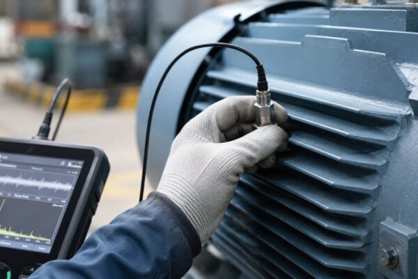
That feedback becomes part of a wider maintenance strategy. Teams that fold heat trace control into their broader operations and maintenance reliability practices usually diagnose failures earlier because they treat controller alarms, sensor integrity, and cable condition as connected issues instead of separate trades.
Where plants get this wrong
The common failure isn't always controller hardware damage. More often, it's one of these:
- Wrong application fit: A simple on off device is used for a process line that needs tighter temperature stability.
- No actionable alarming: The system can energize the circuit, but it can't tell operators whether temperature, current, or ground fault behavior is abnormal.
- Poor visibility: The circuit is physically distributed and no one knows it has failed until a valve sticks, product thickens, or a line plugs.
A chemical plant winterization program is a good example. Freeze protection on utility water may tolerate broad temperature swings. A caustic or viscous product line usually won't. The controller is the point where that difference gets translated into real operating reliability.
Control Methods and Controller Types A Practical Comparison
Not every heat tracing controller should be selected the same way. Some circuits only need a simple freeze-protection response. Others need stable product temperature, low relay wear, and diagnostic visibility. The wrong choice usually creates one of two problems. The plant either overbuys complexity it won't maintain, or underbuys control precision and pays for it later in process instability.
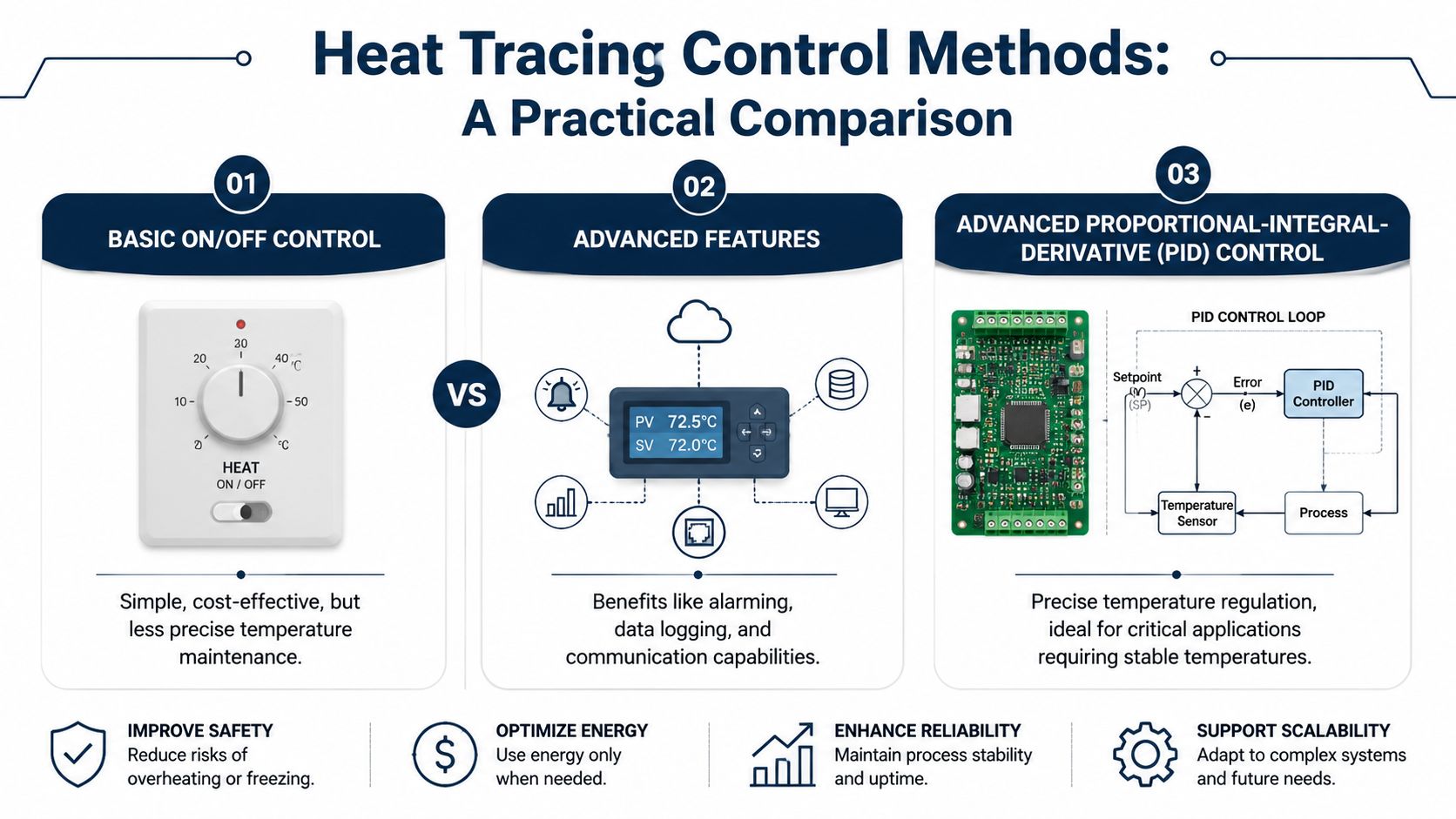
Industrial controllers commonly provide automatic, manual, and on/off modes, with either adjustable deadband control in the 1 to 10 range or PID control, according to industrial controller control mode specifications. That isn't a feature list for procurement. It's a reliability decision.
When basic on off control is enough
Deadband is the temperature range around the setpoint where the controller doesn't switch state. That small buffer matters because it reduces short cycling. Less cycling means less wear on relays and contactors.
For a simple freeze-protection application, on off control often works well.
| Application | Best-fit control approach | Why it works |
|---|---|---|
| Potable or service water line in a manufacturing plant | On off control with deadband | The line only needs to stay above a freeze-risk condition |
| Outdoor drain or washdown line | Basic automatic control | Temperature precision isn't the main risk |
| Intermittently used utility piping | Simple electronic single-point controller | Lower complexity and easier maintenance |
In these cases, a highly tuned loop can be wasted effort. The pipe doesn't need tight thermal stability. It needs dependable energization, sensible alarm limits, and hardware that maintenance can test quickly.
When advanced control earns its keep
Process maintenance is different. A food processing line carrying chocolate, syrup, or edible oil can lose viscosity control if temperature drifts too far. A terminal line carrying a heavy fluid can become difficult to move if heating is inconsistent. In those applications, PID control is worth the extra setup because it improves temperature stability and reduces overshoot.
A controller that is too simple for the process usually fails quietly. The pipe is “warm enough” until it isn't, and by then the quality loss or blockage has already happened.
The choice also depends on controller type:
- Mechanical thermostat: Low complexity, limited visibility, suitable only where consequences are low.
- Electronic single-point controller: Better alarm handling and tighter logic for one circuit or one localized asset.
- Multi-circuit electronic controller: Best where the plant needs centralized data, repeatable settings, and better diagnostic granularity across many circuits.
A common mistake is adding advanced hardware to a circuit that doesn't justify it. If the plant can't maintain sensor calibration, review alarms, and act on the data, the controller becomes expensive wiring. The reverse mistake is worse. Using bare minimum control on a quality-critical line creates hidden process risk.
Practical trade off for self-regulating cable systems
Many teams hesitate when considering a heat tracing controller, and for good reason. Self-regulating cable already adjusts heat output with ambient conditions. That means the controller has to earn its keep.
A controller is usually a reliability asset on self-regulating systems when the circuit is critical, physically remote, or expensive to inspect manually. It may be unnecessary complexity on a low-risk freeze-protection line where a simple protected power feed and periodic inspection are enough.
The deciding questions are practical:
- What happens if this circuit fails and no one knows for hours?
- Does the process need alarms for current, voltage, or ground fault behavior?
- Will centralized monitoring reduce unnecessary callouts?
- Can the maintenance team support another device, sensor, and alarm point?
If the plant can't answer those questions clearly, the controller decision is probably being made on habit rather than reliability need.
Key Selection Criteria for Industrial Applications
Controller selection failures usually start before installation. The specification sheet looks complete, but one missed requirement creates years of nuisance alarms, unstable temperature control, or unsafe application in the wrong area classification. In oil and gas, chemical processing, and power environments, that's not a minor purchasing error. It becomes an operating risk.
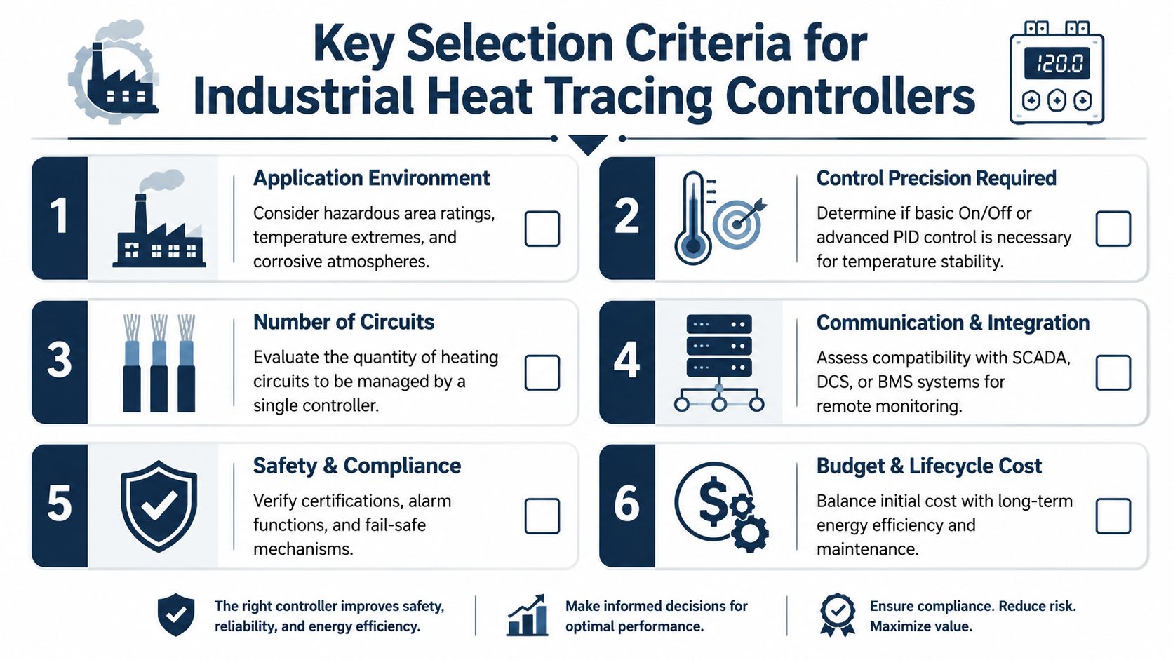
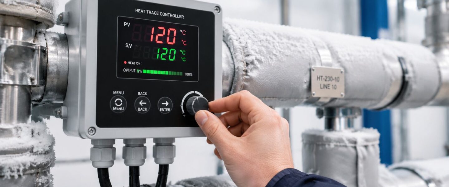
Modern industrial platforms are listed for -60 to +999°C and are designed with Ex-protection for hazardous areas, as described in industrial heat tracing control and monitoring specifications. That wide operating envelope matters because the controller has to survive the environment before it can control the process.
What must be specified before purchase
A plant engineer selecting a controller for a classified-area condensate line should work through these points in order.
Electrical load handling: Match the controller and switching device to the actual circuit load, including startup behavior. A controller that can command a circuit but not handle real field load conditions will fail early or create nuisance trips.
Hazardous area suitability: If the installation is in a classified area, the rating isn't optional. The enclosure, wiring practice, and installed accessories all need to support that classification.
Sensor compatibility: The controller input must match the installed sensor type. An RTD and a thermocouple don't behave the same way, and a mismatch can create believable but wrong readings. That's one of the most dangerous faults because the screen still shows a number.
Number of zones: Single-point control can be fine for a localized asset. For larger facilities, zoning matters because it improves fault isolation. If one tank nozzle circuit fails, the team should know which one, not just that “heat trace has alarmed.”
Reliability mistakes that start in specification
Selection isn't just about capability. It's about maintainability.
A controller with advanced communication features is useful only if the plant will connect it, trend it, and respond to alarms. A very basic device may look attractive until operators need temperature history or maintenance needs fault context. Both under-specifying and over-specifying have a cost.
A quick selection screen helps:
| Selection issue | What to ask in design review | Likely field consequence if missed |
|---|---|---|
| Environment | Will the controller live in weather, washdown, corrosive air, or classified space? | Moisture ingress, enclosure degradation, unsafe installation |
| Control precision | Is this freeze protection or process temperature maintenance? | Product drift, unnecessary cycling, poor stability |
| Circuit count | Does the plant need point-by-point fault visibility? | Slow diagnosis, broad shutdown scope |
| Integration | Will alarms stay local or feed a SCADA or DCS layer? | Missed failures on remote assets |
The best controller selection is the one the plant can actually maintain, test, and interpret under real operating conditions.
A wastewater plant offers a good example. A simple sludge transfer line may only need rugged local control and clear alarms. A chemical dosing skid with tightly managed fluid behavior may need more precise logic and better operator visibility. The selection difference isn't about technology preference. It's about consequence of failure.
Installation and Commissioning to Prevent Future Failures
Many controller failures are installed into the system on day one. The hardware is fine. The field execution isn't. A poorly located sensor, loose termination, or unsealed conduit entry can create intermittent problems that waste hours because the symptoms appear only in cold weather, wet weather, or during startup.
A chemical plant installation makes this obvious. If the sensor is strapped where it sees ambient air instead of true pipe temperature, the controller will react to the wrong condition. The circuit may energize aggressively while the process is already within range, or stay off while a cold spot develops downstream.
Sensor and wiring practices that prevent callbacks
Three field practices prevent a lot of repeat work:
- Place the sensor on the actual thermal reference point: For pipe freeze protection or process maintenance, that usually means firm contact with the pipe, under insulation where appropriate, and away from supports, flanges, and other thermal distortions.
- Protect every wiring transition: Moisture ingress at glands, junction boxes, and conduit entries creates intermittent ground faults that can look like random cable failure.
- Ground correctly and consistently: Good grounding supports personnel safety and reduces noise-related measurement problems that can confuse electronic inputs.
A pulp and paper environment is a common trap because moisture exposure is routine. If an installer leaves even one enclosure or entry point poorly sealed, the controller may run normally for a while and then begin alarming under wet conditions. The failure will appear seasonal or random when its cause is installation-driven.
Commissioning checks that catch hidden defects
Commissioning needs more than power-on verification. Before the system is released to operations, the team should complete a documented check and store it in a maintenance record or linked work package. A structured CMMS implementation guide for maintenance teams is useful here because these baseline values matter later during troubleshooting.
A practical commissioning checklist includes:
- Verify supply conditions: Confirm incoming voltage, breaker status, and basic controller configuration.
- Check sensor plausibility: The displayed temperature should make sense for the actual asset condition.
- Test cable insulation before energizing: Insulation resistance testing helps reveal hidden damage or moisture problems before the circuit is put into service.
- Confirm expected current draw: If the measured load is clearly wrong, stop and investigate before closing the job.
- Function-test alarms: High and low temperature logic, fault annunciation, and any trip functions should be proven, not assumed.
Commissioning isn't paperwork. It's the only time the plant knows the controller, sensor, wiring, and cable were verified together before operations starts changing conditions.
Plants that skip this step usually end up troubleshooting blind because they have no baseline for temperature reading, insulation condition, or normal current behavior.
A Reliability Engineers Guide to Troubleshooting Failures
Troubleshooting usually comes down to one question. Is it the controller or the cable? That's the right question, but it still isn't complete. The failed part might be the sensor, a current transducer, a field splice, an input wiring run, or a configuration error that creates a nuisance alarm. As noted in heat tracing fault-finding guidance focused on resistance and insulation testing, a structured approach should start at the controller and work outward so healthy components aren't replaced by guesswork.
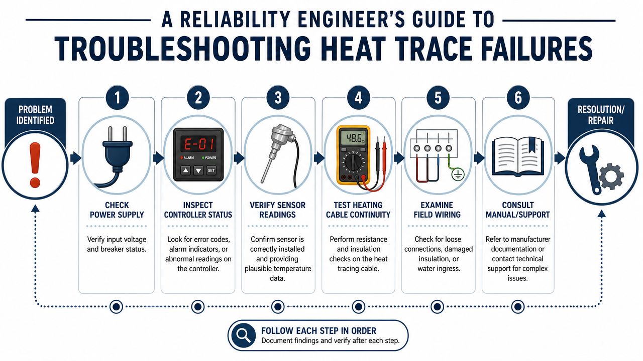
Start at the controller and work outward
A good diagnostic sequence is narrow at the beginning and broader only when needed.
- First, check what the controller thinks is happening. Is it calling for heat? Is there an alarm condition? Is the displayed temperature plausible?
- Second, verify that the output state matches the display. A controller can show a heating demand while the switching device or output path isn't energizing the circuit.
- Third, test the input side. A failed or drifting sensor can make the controller behave perfectly according to bad data.
- Fourth, isolate field components. Once the logic side is checked, test cable continuity, insulation resistance, and field wiring integrity.
This sequence matters because replacing the cable first is expensive and often wrong. A water treatment plant with recurring low-temperature alarms may have a healthy heating circuit and a damaged sensor lead that opens when the conduit contracts in cold weather.
Decision paths for common symptoms
Ground fault alarm with no obvious cable damage
Start local. Inspect field junction boxes, glands, and exposed cable transitions for moisture or mechanical damage. If nothing is visible, isolate the controller from the field circuit as much as practical and test the cable separately with insulation resistance methods.
Then ask whether the alarm is repeatable under the same conditions. If the alarm appears only after washdown, rainfall, or thaw-freeze cycling, the likely suspect is wiring or termination ingress rather than an immediate controller failure.
Low temperature alarm but circuit appears energized
This symptom often sends teams toward the wrong part. If the circuit is energized and the pipe is still cold, one of several things may be true:
- Sensor is reading the wrong location
- Heating cable output is insufficient for actual heat loss
- Insulation is damaged, missing, or wet
- Only part of the circuit is heating
- Controller output indication is misleading because the power path is incomplete
In a long outdoor pipe run, damaged insulation can create a “controller problem” symptom because the control system keeps responding to persistent heat loss it can't overcome.
Repeated trip on one circuit only
When one circuit fails repeatedly and adjacent circuits stay healthy, look for a local issue before blaming the panel or master control logic.
| Symptom | First checks | Most likely fault categories |
|---|---|---|
| Repeated single-circuit trip | Field splice, junction box, cable insulation test | Local wiring damage, moisture ingress, cable fault |
| Alarm with stable process temperature | Sensor reading, setpoint logic, alarm thresholds | Nuisance alarm, sensor drift, configuration issue |
| Controller says heat on but no warming | Output verification, breaker path, contactor state | Failed switching path, wiring open, partial circuit failure |
Don't replace the controller because it generated the alarm. First confirm whether it is detecting a real fault, misreading an input, or failing to drive the output.
Alarm but no freeze event
Nuisance alarms undermine maintenance discipline. If operators see repeated alarms with no process consequence, they stop trusting the system.
A structured root-cause process helps separate bad settings from hardware failure. This is exactly the kind of problem where a formal root cause analysis approach for equipment failures prevents the plant from normalizing alarm noise instead of fixing it.
Common causes include:
- Alarm setpoint too tight for the application
- Sensor mounted where it sees transient cold spots
- Intermittent wiring issue causing unstable readings
- Current measurement problem rather than actual heating loss
The right response is to preserve evidence, compare alarm timing with weather or operating conditions, and test the inputs before changing hardware.
Integrating Controllers for Predictive Maintenance and SCADA
A standalone heat tracing controller protects one circuit. A networked controller architecture changes how the whole plant manages thermal assets. Instead of dispatching technicians to walk pipe racks looking for failed indicators, operations can see alarms, status, and performance data from one location and act before a freeze event or process upset develops.
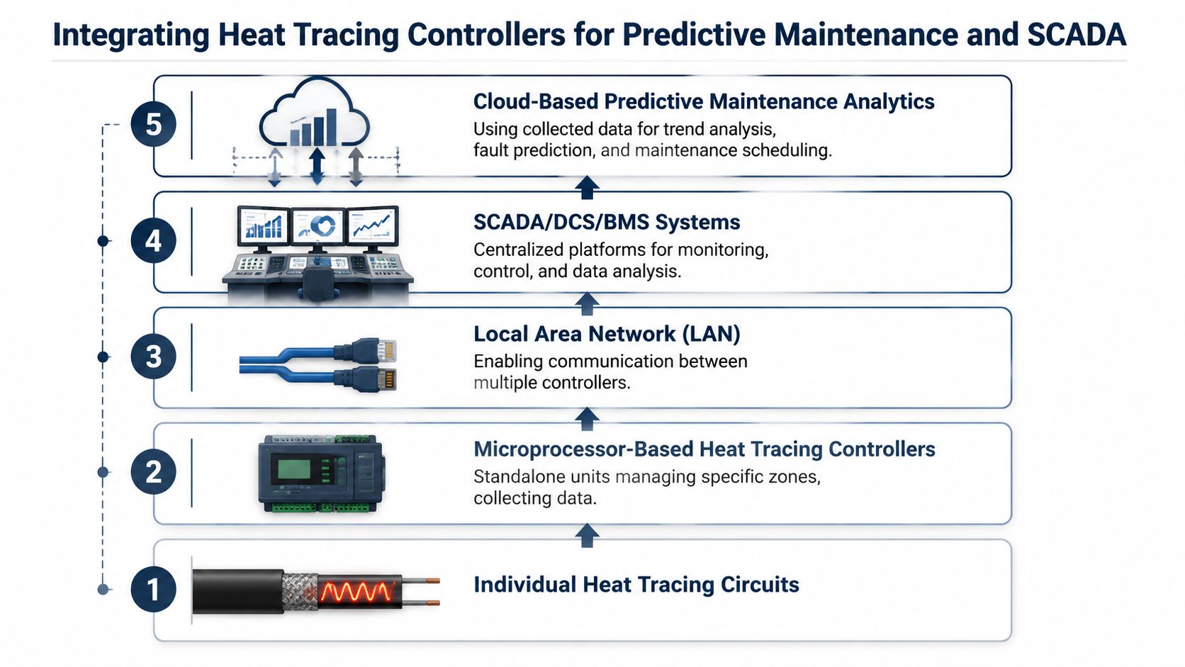
A single-point controller architecture can support centralized supervision. For example, one master unit can supervise up to 32 controllers on an RS485 data highway, according to RS485 heat trace supervision details in the TraceMaster manual. In large facilities, that matters because tracing circuits are distributed across tanks, valves, outdoor pipe racks, and remote process areas.
What centralized visibility changes
A power generation plant is a good example. Auxiliary lines, sampling systems, and weather-exposed piping may all depend on heat trace, but they aren't all equally visible to maintenance staff during a shift. Centralized supervision improves response in three ways:
- Operators can see alarm location quickly: That shortens the time between detection and field action.
- Maintenance can prioritize by asset criticality: A failed circuit on a safety-sensitive or production-critical line gets immediate attention.
- Supervisors gain historical context: Repeated alarms on the same zone often indicate degradation, not random bad luck.
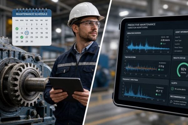
This turns heat trace maintenance from route-based inspection into condition-based response. Plants that are pushing more of their reliability work into connected workflows often connect this data to broader predictive maintenance and machine learning programs so recurring failure patterns don't stay hidden in separate systems.
Which signals actually matter
Not every available data point deserves equal attention. For predictive value, the best signals are usually the ones that drift before failure:
- Ground fault behavior over time: A worsening trend can indicate insulation breakdown or moisture ingress.
- Circuit current behavior: Changes can suggest partial circuit damage or degraded performance.
- Temperature trend stability: If the controller works harder to maintain the same result, the problem may be heat loss, insulation condition, or sensor placement.
A food and beverage site with many short circuits may care most about rapid fault localization. A large outdoor tank farm may care more about trend visibility across widely distributed assets. The point isn't to collect more data. It's to collect the signals that change maintenance decisions.
Your Actionable Heat Tracing Controller Maintenance Checklist
Heat tracing reliability isn't a set-and-forget activity. Controllers drift out of alignment with field reality when sensors loosen, terminals back off, alarm limits are changed without review, or wet insulation masks the actual thermal load. A maintenance checklist keeps the control layer from becoming the blind spot in an otherwise well-managed plant.
Before winter and during routine rounds
For seasonal freeze-protection programs and year-round process tracing, these checks should be standard:
- Inspect enclosure condition: Look for cracked covers, failed seals, corrosion, and signs of moisture.
- Verify status indication: Confirm that displays, LEDs, and local alarm indications are readable and behaving normally.
- Review alarm settings: Make sure high and low temperature alarms still match the process need and haven't been altered casually.
- Check sensor attachment and location: A loose sensor can make a healthy circuit look unstable.
- Confirm field housekeeping: Damaged insulation cladding, open boxes, and unsupported conduit often precede control problems.
A utility water line in a manufacturing plant may only need a concise pre-winter verification. A process-maintenance loop carrying viscous product needs closer review because a small drift in temperature control can create operational consequences long before a freeze occurs.
During shutdowns and turnarounds
Planned outages are the time to do the work that operating conditions make difficult.
Tighten terminations and inspect internal wiring
Thermal cycling and vibration can loosen connections over time.Test alarm functions deliberately
Don't assume that a configured alarm still annunciates properly at the local panel and in the control room.Check cable and wiring insulation condition
Hidden moisture ingress and physical damage are often found during this step.Review recurring fault history
Repeated alarms on the same circuit deserve investigation, not reset-and-run treatment.Compare preventive work against asset criticality
A low-consequence line and a production-critical process loop shouldn't receive the same maintenance depth.
Plants also benefit from deciding whether each circuit should remain on a preventive schedule or move toward a more condition-based strategy. This broader comparison of predictive vs preventive maintenance is useful when heat tracing starts generating enough operating data to support better planning.
A controller becomes a reliability asset only when the plant uses its information to make better maintenance decisions. Otherwise it's just more hardware in the loop.
The practical takeaway is simple. Select the controller to match the consequence of failure. Install it like a measurement device, not just a switch. Troubleshoot from the controller outward instead of replacing parts by instinct. And treat alarm history as evidence, not noise.
If a plant isn't sure whether its heat tracing controllers are improving reliability or adding unnecessary complexity, Forge Reliability can help. A free reliability assessment can identify hidden control-layer risks, weak commissioning practices, recurring fault patterns, and missed opportunities for condition-based monitoring before they turn into unplanned downtime.