A compressor room can sound normal while a compressed-air leak steadily wastes capacity, or a motor bearing can continue turning while its lubrication film begins to fail. By the time a problem becomes obvious through heat, vibration, or production disruption, the maintenance window may already be narrow. Ultrasound condition monitoring gives plant teams an earlier listening point, but only when technicians collect repeatable readings, control for operating conditions, and connect findings to a broader reliability process.
Table of Contents
- Why Ultrasound Matters on the Plant Floor
- How Ultrasound Condition Monitoring Works
- Sensors Couplants and Decibel Scales Explained
- Key Applications From Bearings to Electrical Discharge
- Scanning Procedures Baselines and Signal Interpretation
- Integrating Ultrasound With Vibration Oil Analysis and CMMS
- Build a Reliable Ultrasound Program Starting Today
Why Ultrasound Matters on the Plant Floor
A technician walking a production line may find no visible defect at a pipe joint, valve, or bearing housing. Yet a focused ultrasonic inspection can reveal turbulence from escaping air, a steam trap that isn't seating correctly, or friction caused by inadequate lubrication. These signals are useful because they often appear while equipment is still operating, so the team can inspect assets without waiting for a shutdown.

For example, a food and beverage plant may hear no obvious change from a steam distribution line, even though a passing valve or leaking trap is reducing utility performance. An ultrasound route can help the maintenance planner locate the abnormal point, rank the repair by operational consequence, and verify the condition after work is completed. The same principle applies to a conveyor motor whose bearing is beginning to run dry. The instrument may identify a change in friction before a conventional temperature check becomes decisive.
The method is passive, meaning the instrument listens to naturally occurring high-frequency energy rather than injecting a test signal into the machine. It can support inspections under operating conditions, which makes it practical for compressed-air systems, vacuum equipment, steam systems, rotating machinery, and selected electrical assets. Teams can also use ultrasonic leak detection services when route development, interpretation, or verification requires specialist support.
Practical rule: Ultrasound should answer, “Where has the condition changed, and what should be checked next?” It shouldn't be treated as proof of root cause or remaining life by itself.
That distinction matters. Ultrasound can flag friction, turbulence, impact, or discharge, but the signal may not identify the exact failure mechanism. Vibration, oil analysis, thermography, process information, and visual inspection may be needed to confirm severity and cause.
A decision-grade program therefore depends less on owning an advanced detector and more on controlling the measurement process. The technician needs a defined point, documented settings, comparable machine state, and a clear action path when the trend moves.
How Ultrasound Condition Monitoring Works
Human hearing generally stops at frequencies below 20 kHz, while industrial ultrasound instruments commonly work above that range. Friction between rolling elements and raceways, turbulence through a restriction, and electrical discharge can create high-frequency energy that people can't hear directly. The detector receives that energy and converts it into information the technician can interpret.

A simple field workflow looks like this:
- Choose the failure mode. A leak, bearing lubrication issue, steam trap fault, or electrical discharge calls for a different inspection approach.
- Select the measurement path. Airborne inspection listens through the atmosphere. Contact inspection transfers vibration from the machine surface through a probe or waveguide.
- Control the test conditions. The technician records the asset, point, operating state, sensitivity, and frequency setting.
- Compare the result. The current signal is assessed against a healthy baseline, route history, or a nearby comparable point.
- Verify the action. After lubrication, tightening, valve work, or leak repair, the technician repeats the measurement under comparable conditions.
Airborne ultrasound is especially useful for compressed-air, vacuum, and steam leaks because escaping fluid creates turbulence. It can also support electrical inspection where corona, tracking, or arcing produces detectable high-frequency discharge. A technician scans around fittings, flanges, valve bodies, trap outlets, and electrical enclosures while moving toward the strongest signal.
Structure-borne ultrasound uses a contact probe against a bearing housing, gearbox casing, valve body, or other solid surface. The probe couples with the equipment and receives high-frequency mechanical energy. This approach is useful when airborne noise would make a leak difficult to isolate or when the target is internal friction rather than escaping fluid.
International practice has developed beyond informal listening. ISO 29821:2018 formalized guidance for anomaly severity assessment, examination procedures, safety recommendations, error sources, data interpretation, assessment criteria, and reporting for airborne and structure-borne ultrasound methods. The standard superseded ISO 29821-1:2011, and ISO notes that standards are reviewed every five years. That maintenance cycle signals a mature, maintained practice rather than an improvised technique.
The personnel side matters too. ISO 18436-8:2013 defines qualification and assessment requirements for personnel performing machinery condition monitoring and diagnostics using ultrasound. Plants with multiple sites can use that competence framework to align training, route execution, and audit expectations.
For practical equipment selection, teams can review ultrasound testing equipment according to the failure modes, access limitations, and reporting needs of the plant rather than choosing a device based only on display features.
Sensors Couplants and Decibel Scales Explained
The instrument chain starts at the sensor. A sensor receives ultrasonic energy, a contact probe transfers that energy from the machine surface, and a waveguide helps reach points that are obstructed or unsafe to access directly. For rotating equipment, a technician usually needs a stable contact point on the bearing housing. For leaks, the instrument may use an airborne sensor that scans the surrounding area.
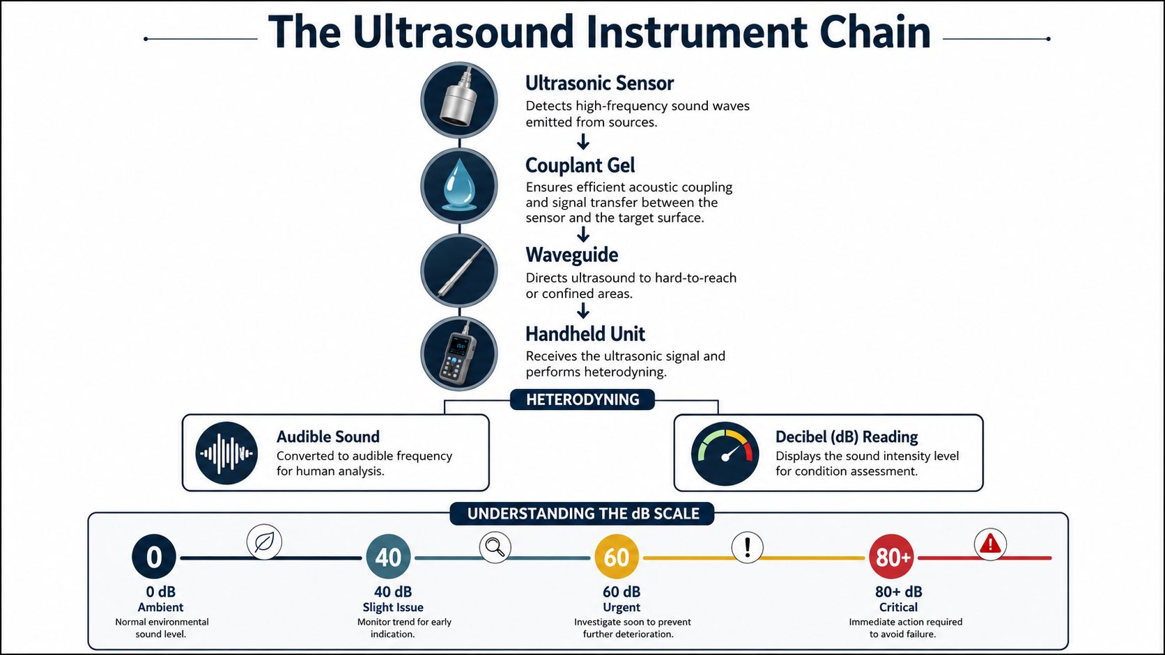
A couplant is a gel or similar material placed between a contact probe and the machine surface. It fills small air gaps, allowing ultrasonic energy to transfer more consistently. Without good coupling, a technician can mistake poor signal transmission for a healthy or changing machine condition. The contact pressure, probe angle, and exact point should remain consistent from one inspection to the next.
Many instruments use heterodyning, a signal-processing method that shifts ultrasonic energy into an audible range. The technician can hear a translated version of the signal through headphones while also reviewing a numerical reading. The sound can help distinguish a smooth, steady condition from a rough, crackling, or irregular one, but the audio impression shouldn't replace recorded measurements.
Industrial ultrasound systems commonly target the 20 kHz to 100 kHz band, while many handheld leak and bearing instruments use a narrower window around 35 kHz to 42 kHz. Technical guidance on airborne ultrasound condition monitoring describes how heterodyning supports interpretation and how trend metrics such as RMS, peak value, and crest factor can reveal changes in high-frequency activity.
Reading decibels as a trend
A decibel, or dB, is a logarithmic way to express signal level. In plant work, the most useful question usually isn't whether a reading is high in isolation. It's whether the reading has changed from the same asset's healthy baseline under a comparable operating state.
A bearing on a lightly loaded motor may naturally produce a different signal from a bearing on a heavily loaded conveyor. A leak reading can also change with pressure, background noise, sensor distance, and the angle of approach. Settings that improve sensitivity can make a small procedural difference look like a real equipment change.
Technicians should therefore record:
- Measurement point: Mark the housing, valve position, fitting, or inspection location.
- Instrument setting: Keep frequency, sensitivity, and mode consistent.
- Operating state: Note speed, load, pressure, flow, and process condition where relevant.
- Signal features: Capture the dB value and, where available, RMS, peak, crest factor, and audio notes.
- Follow-up status: Connect the reading to a work order, inspection, lubrication task, or verification check.
A structured acoustic monitoring approach helps the team preserve this context. The instrument produces the reading, but the maintenance process determines whether that reading becomes useful evidence.
Key Applications From Bearings to Electrical Discharge
Ultrasound earns the fastest operational value where a small change can create energy waste, lubrication damage, process instability, or electrical risk. The best route isn't the one that covers every component equally. It focuses on assets whose failure modes match the strengths of the method.
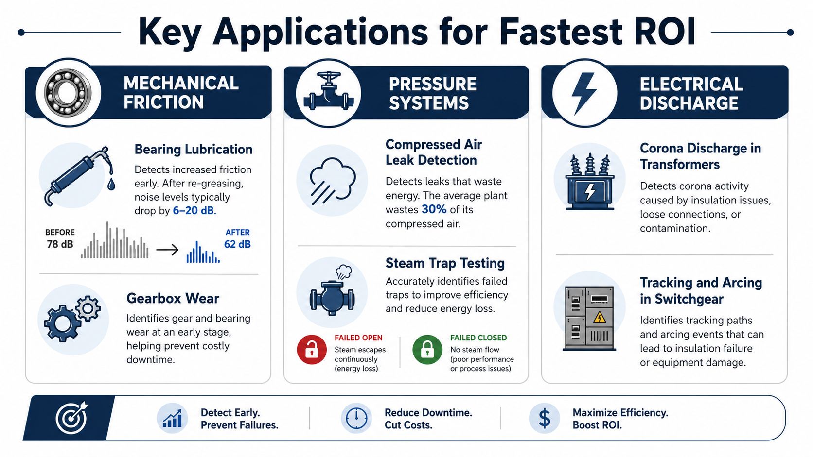
A bearing inspection illustrates the decision logic. A rising friction signal can prompt a lubrication review, while a rough or unstable sound may justify vibration analysis and a planned repair. A technician inspecting a paper mill fan bearing, for example, should compare the signal with the established route history rather than make a replacement decision from one isolated value.
Steam systems require a different interpretation. A healthy steam trap has an operating pattern that differs from a trap stuck open or a trap that fails closed. Ultrasound can help identify abnormal flow and support a decision about whether the repair priority is energy loss, condensate management, process quality, or equipment protection. The same method can assess valve seating, including a valve that passes when it should isolate flow.
Compressed-air and vacuum leaks are airborne targets. The technician scans connections, hoses, regulators, flanges, and fittings, then confirms the location before repair. In a packaging area, isolating a small leak at a quick-connect fitting can be more valuable than inspecting a remote low-criticality branch, especially when the leak affects pressure stability or production equipment.
Electrical inspection requires strict safety controls and qualified personnel. Ultrasound can detect corona, tracking, and arcing around switchgear, transformers, and other energized equipment where access procedures permit inspection. The finding should be escalated through the plant's electrical safety process, not treated as a routine mechanical work order.
| Application | Technique | Typical Signal Cue | Example Asset |
|---|---|---|---|
| Bearing lubrication | Structure-borne contact probe | Rising or rough friction signal compared with baseline | Conveyor motor bearing |
| Steam trap testing | Airborne or contact inspection | Abnormal flow pattern or persistent passing signal | Food and beverage steam trap |
| Valve seating | Contact or airborne inspection | Flow where isolation should occur | Process isolation valve |
| Compressed-air leak detection | Airborne scanning | Localized turbulent hiss after directional scanning | Packaging-line fitting |
| Electrical discharge | Airborne inspection from a safe position | Irregular discharge associated with corona, tracking, or arcing | Switchgear enclosure |
Industrial standards material explicitly includes compressed-air, vacuum, and steam leaks, along with steam trap and valve faults, among practical ultrasound targets. The ISO-related technical material on ultrasound personnel competence reinforces the need to connect the technique to competent examination and interpretation.
For electrical findings, ultrasonic electrical fault detection can provide a focused pathway for plants that need to screen discharge-related conditions while coordinating maintenance and safety requirements.
Scanning Procedures Baselines and Signal Interpretation
A route becomes useful when two technicians can measure the same point and reach comparable conclusions. That requires more than walking past the asset with a detector. It requires a defined measurement location, a repeatable technique, and enough operating context to explain why the signal changed.
Establishing a trustworthy route
The technician should begin with a healthy reference condition. The asset identification, point location, probe type, frequency, sensitivity, speed, load, pressure, and process state belong in the route record. A photograph or marked point can help prevent a later measurement from drifting to a more convenient but acoustically different location.
The first pass should capture the condition before any intervention. If a bearing is suspected of under-lubrication, the technician records the signal before applying grease, performs the lubrication according to the equipment procedure, and captures the post-lubrication result. Guidance for ultrasonic bearing monitoring and acoustic lubrication emphasizes the importance of before-and-after readings and using the post-lubrication value as the baseline when the point was under-lubricated.
A reset baseline isn't a way to hide a worsening condition. It reflects a verified change in machine state. The work order should explain why the baseline moved, what lubricant was applied, and whether the signal stabilized afterward.
Interpreting changes without overreacting
A widely used rule of thumb treats a rise of about +8 dB above baseline as a possible indication of insufficient lubrication or an early bearing problem, about +16 dB as a possible sign of bearing damage, and about +35 dB as a critical failure signal. Mechanical condition-monitoring guidance makes clear that these are relative changes, not universal absolute limits.
A peer-reviewed ultrasound emission bearing assessment uses three condition bands, 0 to 7.5 as good, 7.5 to 17 as acceptable, and greater than 17 as unacceptable. The published bearing assessment study provides a severity scale that can support escalation alongside vibration and operational evidence.
Those thresholds should trigger a decision pathway, not an automatic part replacement:
- Confirm the reading: Repeat the measurement at the same point and check the instrument setup.
- Check the operating state: Look for speed, load, pressure, flow, or process changes.
- Review recent work: Confirm lubrication, alignment, tension, valve operation, or electrical activity.
- Select the next test: Use vibration, thermography, oil analysis, visual inspection, or process data to narrow the diagnosis.
- Document the action: Create or update the CMMS record and schedule verification.
Variable-speed drives and intermittent process loads create special risk. A bearing measured during acceleration shouldn't be compared casually with one measured at steady speed. If the plant can't hold a stable condition, the route should capture the range of normal states and classify readings by state instead of forcing them into one misleading trend.
Integrating Ultrasound With Vibration Oil Analysis and CMMS
Ultrasound works best as an early warning and verification layer inside a larger condition-monitoring architecture. It can flag friction, leakage, turbulence, or discharge, then direct attention to the test most likely to confirm severity. Vibration can help characterize rotating faults, oil analysis can reveal lubricant and wear conditions, and thermography can show heat associated with developing problems.
A motor-driven pump provides a practical example. An ultrasound trend may indicate increased bearing friction. The reliability engineer can then review vibration for bearing defect patterns, check lubrication history, examine temperature, and inspect process conditions such as cavitation risk. If the evidence points to under-lubrication, the team can lubricate according to the procedure and use ultrasound for immediate verification, while vibration confirms whether the mechanical condition remains stable.
Choosing route-based or continuous monitoring
Handheld route inspection fits assets where access is easy, failure progression is understood, and periodic coverage provides enough warning. It also works well for broad screening of leaks, traps, valves, and bearings across a plant.
Permanent or continuous sensing deserves consideration when a critical asset changes rapidly, operates intermittently, is difficult to access, or has a failure consequence that justifies immediate notification. A compressor bearing, high-consequence process pump, or inaccessible motor may warrant continuous observation, while a low-criticality utility fitting may remain on a route.
The market is moving toward integrated ultrasound-based machine maintenance and condition monitoring. One 2026 market estimate placed the market at USD 805.15 million in 2025, USD 869.40 million in 2026, and projected USD 1.40 billion by 2032 at an 8.24% CAGR. The market estimate also distinguishes handheld inspection from permanently mounted and continuously monitored sensing.
Turning findings into work
A CMMS should contain the asset, measurement point, baseline, current reading, operating state, severity, recommended action, owner, and due date. The work order should also preserve before-and-after evidence so the team can verify whether a repair or lubrication task changed the condition.
Personnel competence must remain part of the design. The international qualification framework described earlier gives plants a basis for training and assessment, especially when multiple sites need consistent inspection quality. A provider such as Forge Reliability can support condition monitoring that includes ultrasonic emissions, along with vibration, oil analysis, thermography, and related reliability methods, when a plant needs external engineering capacity.
Build a Reliable Ultrasound Program Starting Today
A plant doesn't need to instrument every asset before ultrasound becomes useful. The practical starting point is a criticality review that identifies where leakage, lubrication failure, valve passing, steam loss, cavitation, or electrical discharge could create disproportionate downtime, safety exposure, product loss, or energy waste.
A maintenance manager can build the first route around a focused asset group:
- Rank the assets: Use failure consequence, detectability, access, and operating criticality.
- Match failure modes: Assign airborne or structure-borne inspection according to the condition being sought.
- Mark measurement points: Define the probe position, settings, and operating state.
- Capture healthy baselines: Record readings before intervention and preserve the context.
- Set escalation rules: Use relative changes, condition bands, and engineering judgment.
- Connect the CMMS: Convert confirmed findings into owned work, then verify the result.
- Review route quality: Remove points that produce inconsistent data and improve training where repeatability is weak.
A mining conveyor motor demonstrates the value of this sequence. A small increase above baseline may prompt a lubrication review and closer follow-up, while a larger change can justify vibration confirmation and planned repair. The maintenance team gains time to choose the intervention instead of discovering the problem after a seized bearing stops material movement.
The strongest program treats ultrasound as triage and verification, not as a standalone diagnostic. It finds where attention belongs, confirms whether an intervention helped, and supplies an early signal that other technologies can investigate in greater depth. Consistent baselines, controlled operating states, competent personnel, and disciplined CMMS follow-through turn that signal into a reliability decision.
Forge Reliability's free reliability assessment can help plant teams identify suitable ultrasound applications, review critical assets and failure modes, evaluate route or continuous-monitoring needs, and connect findings with broader predictive maintenance and CMMS practices.
Forge Reliability offers a free reliability assessment focused on critical equipment, ultrasound and other condition-monitoring opportunities, baseline quality, and maintenance workflow integration. Visit Forge Reliability to request an assessment and discuss practical steps for prioritizing assets, improving inspection decisions, and reducing unplanned downtime.