
A maintenance team knows the pattern. A compressed air leak keeps showing up on the utility bill but not on the work order list. A bearing passes vibration on the last route and still fails before the next shutdown. A steam trap looks normal from a distance while energy loss keeps climbing. Those problems aren't rare, and they usually don't start with heat or low-frequency motion. They start with friction, impacting, and turbulence that operators can't hear unaided.
That's where ultrasound testing equipment earns its place. In practical terms, it works like a stethoscope for machines. It lets technicians hear the high-frequency signatures of early mechanical wear, leaking gas, unstable valves, and electrical discharge before those conditions become obvious to other tools or to the human ear.
Most plants already understand that part. The bigger miss is what happens after purchase. Teams debate handheld versus mounted sensors, airborne versus contact probes, and route design, but many never put the same discipline into maintaining the ultrasound device itself. In harsh plant environments, that gap matters. A dirty probe face, damaged cable, loose connector, or contaminated transducer can turn a good program into a misleading one.
Table of Contents
- Introduction: The Hidden Failures Costing You Uptime
- How Industrial Ultrasound Detects Failures
- Selecting the Right Ultrasound Testing Equipment
- Matching Probes and Sensors to Your Assets
- Mastering Data Collection and Diagnosis Techniques
- The Critical Need for Industrial Calibration and Verification
- Integrating Ultrasound into Your Reliability Strategy
- Conclusion: Start Hearing Your Next Failure Before It Happens
Introduction: The Hidden Failures Costing You Uptime
Ultrasound finds failures that stay invisible to many standard inspections because it targets the earliest high-frequency energy released by a defect. Friction shows up when surfaces begin to run dry or rough. Impacting appears when looseness, cracked gear teeth, or defected rolling elements start striking rather than rolling smoothly. Turbulence develops when gas or steam escapes through a restriction, or when a valve or trap no longer behaves as intended.
For reliability engineers and plant managers, that makes ultrasound one of the few tools that can cover mechanical, leak, valve, and electrical work with one platform. A food and beverage site might use it one hour to check washdown-area bearings, then switch to compressed air leak detection in packaging, then inspect a suspect valve in a utility corridor. That flexibility is exactly why so many teams buy the equipment and expect quick results.
Practical rule: Ultrasound works best when the team treats it as a decision tool, not just a listening gadget.
The first decision is always failure mode. If the plant is chasing early bearing distress, the goal isn't just to collect a number. The goal is to hear and trend a change in friction before heat rises or vibration broadens. If the plant is losing steam, the task isn't just “survey the line.” The task is to separate normal flow sounds from abnormal turbulence.
Why the stethoscope analogy fits
A stethoscope doesn't repair a patient. It helps a skilled person detect patterns that point to the next action. Industrial ultrasound works the same way. The sensor translates ultrasonic activity into a form the technician can hear and trend. The value comes from connecting that sound to machine behavior.
Three examples make the point quickly:
- Bearing on a process pump: Rising friction often appears before temperature alarms.
- Check valve on a condensate line: Irregular internal flow can create a rough, unstable signature.
- Compressed air leak in a plastics plant: Turbulence creates a sharp airborne leak sound even in a noisy area when the right sensor is used.
The plants that get the best return don't stop at buying an instrument. They match the device to the asset, train technicians to collect repeatable readings, and verify the health of the ultrasound equipment itself. That last step is where many programs lose credibility without realizing it.
How Industrial Ultrasound Detects Failures
A technician can walk past the same pump for months and miss the first signs of trouble because nothing looks wrong yet. Ultrasound helps catch the change that comes before heat, before visible damage, and often before vibration gives a clear warning on slower or lightly loaded assets.
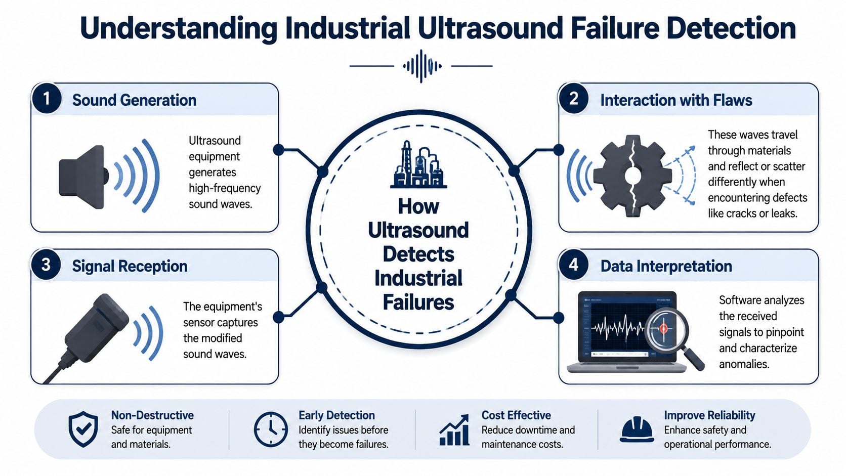
Ultrasound instruments detect high-frequency sound produced by friction, impacting, and turbulence, then convert it into a signal the technician can hear, trend, and compare over time. That matters because many failure modes start with a small increase in surface contact or unstable flow long before they create a large temperature rise or a strong low-frequency vibration signature.
Friction, impacting, and turbulence
Friction is the pattern behind many bearing findings. As lubrication film breaks down or metal surfaces start interacting more directly, ultrasonic activity rises. In the field, that often shows up first as a sharper sound quality or a steady increase in the measured level at the same test point. If readings are taken consistently, the team gets time to relubricate, inspect, or plan a changeout before the asset degrades into a forced outage.
Impacting points to intermittent contact. A damaged rolling element, a cracked gear tooth, or mechanical looseness can create repeating bursts instead of a steady friction signature. In heterodyned audio, those defects usually sound rough, clicking, or pulsed. The pattern matters as much as the number.
Turbulence drives leak and valve applications. Gas or steam moving through a small opening produces ultrasonic noise because the flow becomes unstable at the restriction. That is why ultrasound is so effective for compressed air surveys, steam trap work, and valve seat checks. Teams that want a practical breakdown of leak use cases can review these industrial ultrasonic leak detection methods.
The hard part is not hearing sound. The hard part is knowing whether the sound is abnormal for that asset, at that load, in that process state.
Why ultrasound often finds problems early
Ultrasound responds well to the first physical changes in a failure sequence. A bearing does not need to run hot before friction increases. A leak does not need to be large before turbulence becomes detectable. That gives reliability teams a useful lead time, especially on assets where monthly routes are realistic but continuous vibration coverage is not.
It also has a practical advantage on busy plant floors. High-frequency sound is directional. That helps the technician isolate a source in areas where background mechanical noise would make other methods harder to interpret.
Detection quality depends on the condition of the instrument
Weak programs lose trust when a technician may do everything right, use the correct test point, keep contact pressure consistent, and still collect misleading data if the ultrasound testing equipment itself has drifted, taken water ingress, developed cable damage, or has a worn sensor face.
In harsh industrial environments, that is not a side issue. It is part of detection. A contaminated contact probe can dull response. A damaged headset or loose connector can distort what the technician hears. A sensor knocked out of tolerance can make trend data look stable when the machine is changing, or look worse when the asset is fine. If the instrument is not maintained and checked routinely, the failure is in the inspection process, not just in the machine.
Handheld route tools and continuous monitoring detect different risk profiles
Handheld instruments fit route-based work where the team can revisit assets at a defined interval and compare readings against a baseline. That covers a large share of pumps, motors, bearings, valves, and utility systems.
Continuous monitoring earns its place on assets with poor access, rapid failure progression, or high production consequence. A critical compressor, an enclosed drive, or equipment in a hazardous or remote area may need permanent sensing because missing a short degradation window costs more than the hardware.
Start with the failure speed and the consequence of missing it. That sets the monitoring method faster than any feature sheet.
What to verify before trusting a reading
Before acting on an ultrasound finding, check four things:
- The signal matches the expected failure mode. Friction, impacting, and turbulence do not sound the same.
- The reading was taken at a repeatable location. A good instrument still gives bad trends if test points drift.
- Operating conditions are comparable. Load, speed, and process state change the signature.
- The instrument and sensor are known to be in good condition. Verification and calibration protect the credibility of the diagnosis.
That last point gets skipped too often. Teams focus on machine defects and forget that ultrasound equipment also lives in heat, moisture, dust, vibration, and rough handling. If the tool is not checked, cleaned, and calibrated on schedule, the plant can end up making maintenance decisions from bad input.
Selecting the Right Ultrasound Testing Equipment
Buying ultrasound testing equipment without tying it to actual plant tasks is how budgets get wasted. The right instrument for a route technician in a food and beverage plant isn't automatically the right instrument for a reliability engineer supporting outdoor utilities, nor for a team inspecting inaccessible process assets in a chemical unit.
Start with use cases, not feature lists
A team should begin with the applications that will justify the purchase in the first year of use. Common high-value categories include:
- Bearing monitoring: Best when early lubrication and wear decisions matter.
- Leak detection: Strong fit for compressed air, vacuum, gas, and some steam loss work.
- Valve and steam trap inspection: Useful where process inefficiency and hidden failure create operating losses.
- Electrical inspection from a safe distance: Valuable for detecting discharge-related conditions where direct contact isn't appropriate.
A maintenance manager in a food and beverage facility usually faces a clear trade-off. A standard handheld unit may cover mechanical and utility work, but washdown areas change the selection logic. If water exposure, frequent sanitation, and harsh cleaning are routine, a more rugged environmental design often protects the investment better than replacing damaged gear later.
Handheld and mounted systems serve different jobs
Portable tools dominate route-based reliability because technicians can carry one instrument through multiple asset classes in a single shift. That market position reflects real plant behavior, not just product preference. The broader equipment market numbers support that trend, with portable equipment leading at USD 1.215 billion inside the USD 2.20 billion 2024 market, as detailed in this market outlook for ultrasonic testing equipment.
Mounted systems should be reserved for conditions like these:
- Critical assets with fast failure progression
- Unsafe or difficult access points
- Machines where route intervals leave too much risk
- Locations where the plant already reviews continuous condition data
Key Specifications for Ultrasound Testing Equipment
| Specification | What It Means | Look For In Reliability Applications |
|---|---|---|
| Frequency range | The range the instrument can tune for different applications | Flexible settings that support bearings, gears, valves, steam traps, and leak work |
| Sensitivity | How well the device detects weak ultrasonic signals | Stable response for early leak detection and low-energy mechanical changes |
| Data storage capacity | How much route data, audio, and trend history the unit can retain | Enough onboard storage for route collection and later review |
| Environmental rating | How well the device tolerates dust, moisture, chemicals, and harsh handling | Durable construction suited to plant floor contamination and cleaning exposure |
| Display and interface | How readings, trends, and settings appear to the user | Clear screens and simple navigation that reduce field errors |
| Sensor compatibility | Which probe types the instrument can accept | Support for airborne, contact, magnetic, and specialty probes |
| Audio quality | How clearly heterodyned sound can be heard and compared | Crisp audio that helps technicians separate rough from clean signatures |
Scenario-based selection
Different jobs call for different front-end hardware and technique.
- Suspected compressed air leak in a noisy production area: Use an airborne sensor that helps isolate directional sound. The goal is to separate leak turbulence from background plant noise.
- Slow-speed bearing on a critical pump: Use a contact sensor, preferably with a repeatable mounting method. Consistent point placement matters more than convenience.
- Valve survey in a utility corridor: Use a contact approach that lets the technician hear internal flow character rather than ambient noise.
- Electrical survey on enclosed gear: Use a sensor that allows safe stand-off distance where plant procedures permit.
A team comparing route hardware and broader condition-monitoring choices can also review ultrasonic testing and vibration monitoring equipment selection guidance to fit ultrasound into a wider predictive program.
The best instrument isn't the one with the longest feature sheet. It's the one the team can use consistently on the assets that create the most downtime risk.
Matching Probes and Sensors to Your Assets
A plant can buy a capable instrument and still get weak results if the probe does not fit the asset or the route. Probe choice sets the signal path, the amount of background noise you fight, and how repeatable the reading will be six months from now after the equipment has been dropped, wiped down, and carried through heat, dust, and washdown areas.
The first question is simple. Is the sound traveling through air, or through the machine structure? Get that wrong and the route becomes noisy, slow, and hard to trust.
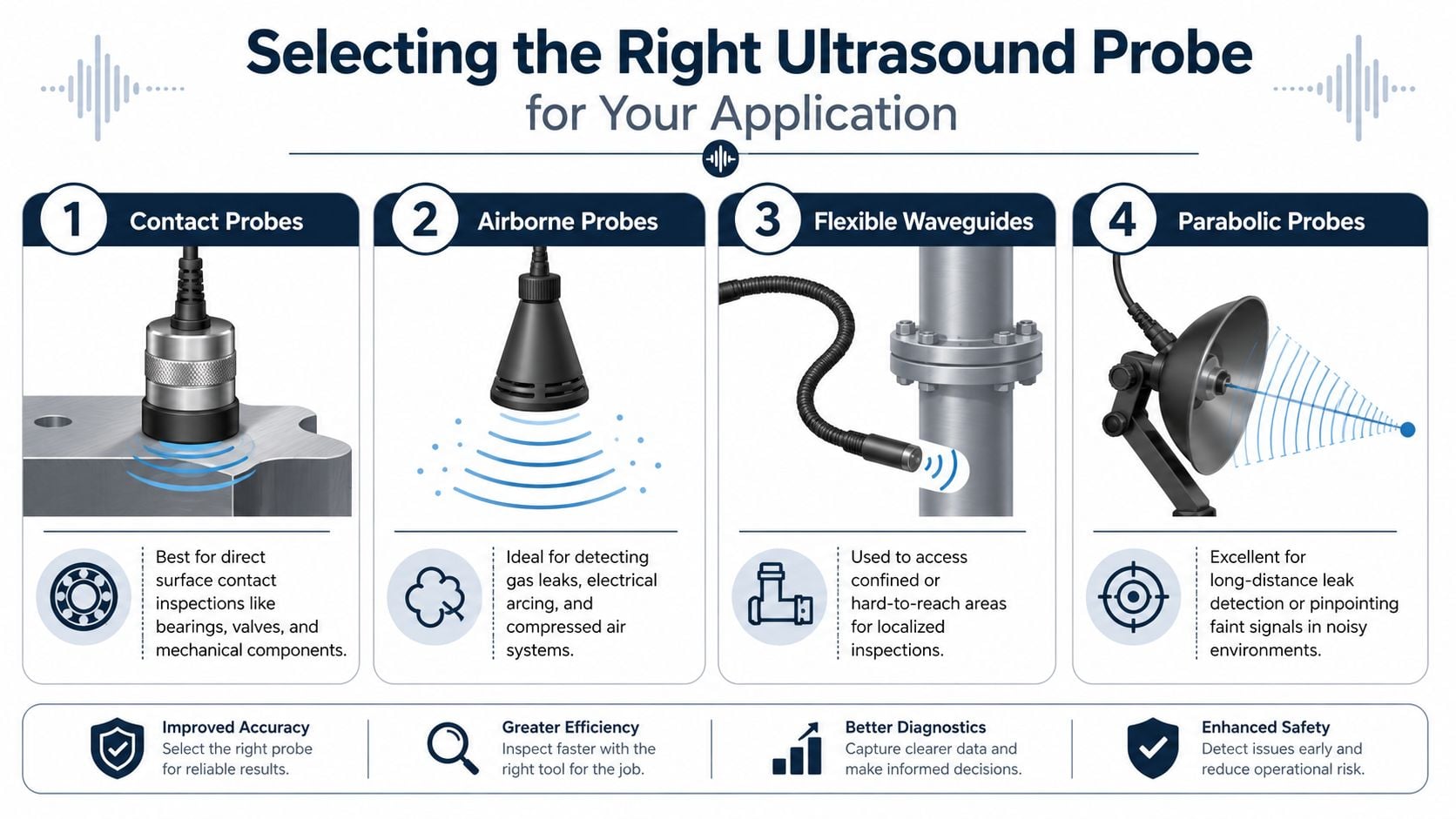
Airborne sensors for leaks and electrical work
Airborne probes fit problems that radiate into open space. Compressed air leaks, vacuum leaks, gas leaks, and many electrical inspections fall into that group. They let the technician scan quickly and stay off the asset, which matters around energized equipment and hard-to-reach piping.
Directionality is the advantage. In a loud plant, an airborne probe can still isolate turbulence from a leak or the distinct character of electrical activity, while audible noise bounces around the area and confuses the search. For switchgear and overhead assets, stand-off accessories or parabolic attachments can help narrow the target without forcing close exposure.
That convenience has limits. Airborne work is sensitive to distance, line of sight, reflective surfaces, and operator technique. If the sensor grill is dirty, the windscreen is damaged, or the front end has taken a few hits in the tool bag, the technician may blame the process when the problem is the condition of the probe itself.
Contact sensors for mechanical condition
Contact probes fit assets where the fault energy travels through metal before it reaches the sensor. Bearings, gearboxes, valve bodies, steam traps, and many low-speed mechanical assets are better checked this way because contact transmission cuts ambient interference and gives more repeatable results.
Repeatability matters more than speed on a route. A magnetic mount, threaded stud, or other fixed contact method usually outperforms hand pressure because it controls placement and coupling. On critical bearings, that consistency is what turns a reading into a trend instead of a guess.
For lubrication programs, contact ultrasound works best when the team ties the probe style, mounting method, and grease procedure together. Plants refining that workflow can use ultrasonic bearing monitoring and acoustic lubrication guidance to standardize decisions and cut over-greasing.
Match the sensor to the failure mode and the environment
Probe selection is not only about the asset. It is also about the inspection environment and how well the sensor will hold calibration and sensitivity between checks.
- Compressed air header in a noisy production bay: Use a directional airborne sensor that can isolate the leak path from surrounding noise and keep scan time short.
- Motor or pump bearing on a repeat route: Use a contact sensor with a fixed or repeatable mount. Stable coupling beats convenience.
- Steam trap or valve body in a hot utility area: Use a contact probe rated for the temperature and protect the cable from hard bends and jacket damage.
- Electrical cabinet or overhead line hardware: Use an airborne or stand-off sensor that supports safe distance and clear targeting.
- Remote or harsh installations with broader condition monitoring needs: Review how ultrasound fits alongside other predictive maintenance sensors so the sensing method matches the failure physics.
In harsh plants, probe care is part of asset care. Dirty threads, worn tips, loose connectors, cracked strain reliefs, and magnets packed with fines all change the quality of the signal. Teams often spend weeks questioning technician technique when the actual issue is a damaged contact point or a sensor that has drifted after repeated exposure to heat, moisture, and impact.
A probe does not just collect sound. It shapes what the technician can hear, and if you do not maintain and verify that front-end hardware, even a disciplined route will drift into bad decisions.
Mastering Data Collection and Diagnosis Techniques
Most ultrasound mistakes aren't hardware failures. They're method failures. The route point isn't repeatable. The frequency setting doesn't match the asset. The baseline was never established. Or the technician trusts the instrument reading while ignoring what the sound says.

Build the route around baselines
For mechanical condition monitoring, each machine needs its own normal reference. A pulp and paper mill with large roller bearings is a good example. One bearing housing may naturally run at a very different ultrasonic level than another because load, speed, mounting, and lubrication state differ. Without a baseline, teams compare unrelated assets and draw weak conclusions.
A sound route includes:
- Fixed measurement points on housings, valve bodies, or access locations
- Repeatable sensor placement using the same contact style each time
- Operating-state awareness so readings are taken under comparable load and process conditions
- Trend review, not single-point reaction
Use the right frequency and listen for a clean cycle
Frequency selection should follow the asset type. According to application guidance on mechanical ultrasound analysis, analysts typically set the contact probe to 30 kHz for bearings and gears and 25 kHz for valves and steam traps, then listen through 3 to 4 cycles to confirm a clean cycle. If the signature becomes loud or rough at any point, the pattern can indicate adhesive wear, abrasive wear, or fatigue.
That listening step is where experienced technicians separate useful data from false confidence. A clean, repeatable cycle sounds orderly. A dirty cycle sounds unstable. Numbers trend the severity. Audio often explains the mechanism.
"If the route only records dB and nobody reviews the sound, the team is using half the instrument."
Turn dB changes into maintenance action
For bearing condition, thresholds are only useful when they trigger a specific response. The practical interpretation from SDT's mechanical condition monitoring reference is straightforward:
- Above +8 dB from baseline: Check lubrication condition, lubrication amount, and early failure indicators.
- At 12 to 16 dB: Treat the bearing as degrading. Plan inspection or replacement based on criticality.
- Above 30 dB: Escalate immediately. The condition warns of imminent catastrophic failure.
For a process pump bearing, that might mean adding controlled lubrication only after confirming the sound pattern supports it. For a gearbox bearing already showing rough audio and increased gain, adding grease alone may waste time and hide damage.
Don't assume the instrument stays accurate on its own
A common plant-floor assumption is that ultrasound devices are rugged enough to trust unless they stop powering on. That assumption causes bad calls. The neglected issue is the health of the testing equipment itself. In industrial environments, probes get dropped, cables get kinked, connectors loosen, and residue builds up on contact surfaces.
A simple field verification checklist helps reduce that risk:
- Inspect cable strain points: Look for cuts, hard bends, and intermittent connections.
- Clean probe faces: Remove couplant residue, oil, and embedded dirt before routes.
- Check connector fit: Loose connectors often create unstable or misleading readings.
- Verify repeat response: Compare a known reference point or known stable asset over time.
- Review audio quality: Distorted or inconsistent sound may indicate probe or cable issues.
Plants expanding into broader connected condition monitoring sometimes pair route ultrasound with other predictive maintenance sensors so the team can compare friction, temperature, vibration, and process context before making a maintenance call.
For teams formalizing route design and reporting, ultrasonic testing maintenance applications can serve as a useful operating framework.
The Critical Need for Industrial Calibration and Verification
A technician finishes a leak route on night shift and reports a sharp increase in compressed air loss in one production area. Maintenance burns half a day chasing leaks that are not there. Ultimately, the problem was a damaged sensor cable that started cutting out whenever the probe was held at a certain angle.
That failure pattern is common in plants. Ultrasound teams spend a lot of time training people to hear bad bearings, arcing, and leaks, but far less time checking whether the instrument itself is still telling the truth. In a mill, refinery, or chemical unit, probes get knocked off carts, connectors collect grime, cable jackets harden, and reference response drifts. The device may still power on and pass a quick function check. That is not the same as being fit for diagnosis.
Why verification affects diagnosis quality
The weak point is rarely software. It is the sensor chain: probe face, cable, connector, headset, and the way the instrument responds to a known condition. ASNT's overview of ultrasonic testing explains the method, but the plant-floor lesson is simpler. Small defects in the instrument create bad maintenance calls long before total failure shows up.
I have seen a contaminated contact probe push a lubrication route toward over-greasing. I have also seen airborne surveys get written off as inconsistent when the actual issue was a loose connector at the sensor. Both cases waste labor. The worse outcome is false confidence. A team trusts the reading, schedules the wrong work, and leaves the actual defect in service.
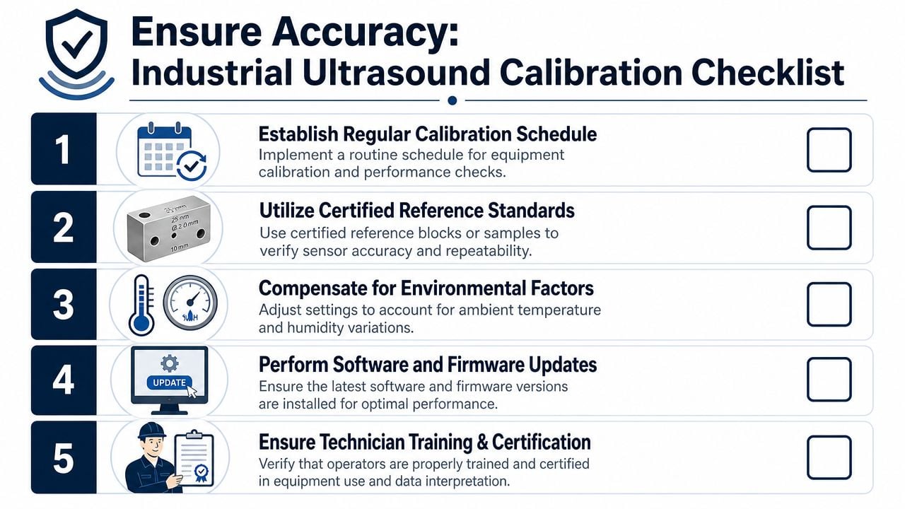
Set a verification routine that matches the environment
Harsh service changes the inspection interval. A lab-style annual calibration mindset is too loose for route instruments that live around dust, washdown, heat, oil mist, and vibration. Plants need two levels of control: quick field verification before use, and formal calibration or performance confirmation on a defined schedule.
A practical weekly routine should include:
- Probe face inspection: Remove residue, oxidation, dried couplant, and embedded dirt.
- Cable integrity check: Flex the cable near strain points and watch for unstable response.
- Connector inspection: Check fit, corrosion, thread damage, and contamination.
- Reference response check: Compare against a known stable condition, reference block, or designated asset point.
- Battery and headset check: Low power and poor audio output can mimic weak or inconsistent signal quality.
- Storage review: Keep sensors protected from crushing, heat, moisture, and loose-toolbox damage.
Plants with formal PdM programs usually document these checks the same way they document route completion. That matters. If a reading looks suspicious two weeks later, the team can determine whether the machine changed or the instrument did.
The broader framework is familiar to any reliability group that already manages instrumentation. These sensor calibration best practices adapt well to ultrasound, especially for defining reference checks, handling out-of-tolerance tools, and keeping records tight enough to trust trend data.
Calibration discipline protects ROI
The return on ultrasound does not come from owning the instrument. It comes from correct decisions. If the tool is drifting, every route, grease recommendation, leak estimate, and screening result becomes harder to trust. That drives repeat inspections, unnecessary work orders, and missed defects.
A disciplined program sets acceptance limits, names who can verify equipment, and removes questionable probes from service fast. Teams that need help building that structure often use outside support for industrial ultrasonic testing services to standardize reference checks, route repeatability, and instrument care in the same workflow.
Treat the ultrasound kit like any other production-critical asset. Inspect it. Verify it. Calibrate it on purpose. That is how plants keep diagnostic accuracy from degrading in the background.
Integrating Ultrasound into Your Reliability Strategy
Ultrasound creates the most value when the plant stops treating it as a specialty tool and starts using it as part of the normal reliability system. The strongest programs don't build separate worlds for vibration, lubrication, thermography, and route inspection. They use each method where it sees the failure mode earliest and most clearly.
Add ultrasound where other methods have blind spots
In an existing predictive program, ultrasound often fits in three places first:
- Lubrication routes: Use contact ultrasound to guide condition-based grease decisions.
- Utility loss surveys: Add airborne leak checks to compressed air and vacuum systems.
- Electrical and valve screening: Use ultrasound as an early warning before intrusive work or shutdown planning.
A process plant may already have vibration routes on pumps and motors. Adding ultrasound at the same points can help the team distinguish between early friction, poor lubrication, and a defect that's already progressing. That's especially useful when the vibration trend changes slowly or remains ambiguous.
Build around criticality and consequence
North America holds 38.9% of the global ultrasonic testing market and was valued at USD 893.7 million in 2025, while the market is projected to grow at a 9.2% CAGR through 2035, according to Fortune Business Insights' regional ultrasonic testing market data. That adoption reflects practical value in sectors where reliability consequences are high, including oil and gas, power generation, and chemical processing.
For plant operations leaders, that matters because ultrasound supports more than one business objective at once:
| Reliability objective | How ultrasound helps |
|---|---|
| Reduce unplanned downtime | Detect early friction, impacting, and leak-related failure modes |
| Lower energy waste | Find compressed air and steam losses that don't show up on rounds |
| Improve safety | Screen some electrical and pressurized-system issues from safer positions |
| Prioritize maintenance labor | Separate assets that need immediate action from those that can wait |
A team rolling out or maturing this capability can use industrial ultrasonic testing services to support route design, inspections, or program development where in-house bandwidth is limited.
One disciplined program beats isolated inspections
A plastics plant gives a good example of the integrated model. Contact ultrasound on extruder bearings can support lubrication and bearing health decisions. Airborne ultrasound can find compressed air losses around molding cells. Valve and steam trap checks can support utility efficiency. Those are different tasks, but they all use the same core capability: hearing high-frequency evidence before the process creates a larger cost.
The strategic point is simple. Ultrasound isn't just another instrument in the cabinet. Used correctly, it helps the plant decide where to spend labor, what to fix first, and which assets need closer surveillance.
Conclusion: Start Hearing Your Next Failure Before It Happens
Ultrasound testing equipment becomes valuable when a plant applies it with discipline. That means understanding what the technology is detecting, selecting the right instrument for the route, matching probes to the failure mode, and collecting data in a repeatable way that supports real maintenance decisions.
It also means rejecting the idea that the device itself can be ignored. In industrial environments, verification and basic care matter just as much as technician skill. A dirty probe, damaged cable, or unstable connector can undermine a bearing route, leak survey, or valve inspection.
For reliability engineers, maintenance managers, and plant operations leaders, ultrasound fills an important gap. It can detect early mechanical friction, isolate leak-related turbulence, support safer electrical screening, and strengthen lubrication and inspection routes across a wide range of assets. When it's integrated into a broader reliability strategy, it helps teams protect uptime and spend maintenance labor where it changes risk.
A no-cost reliability assessment from Forge Reliability can help identify where ultrasound will have the biggest impact in a facility, whether the immediate need is bearing monitoring, leak detection, route development, or improving confidence in existing condition data.