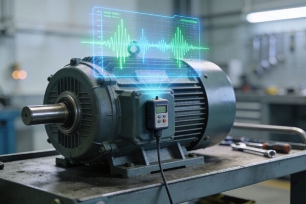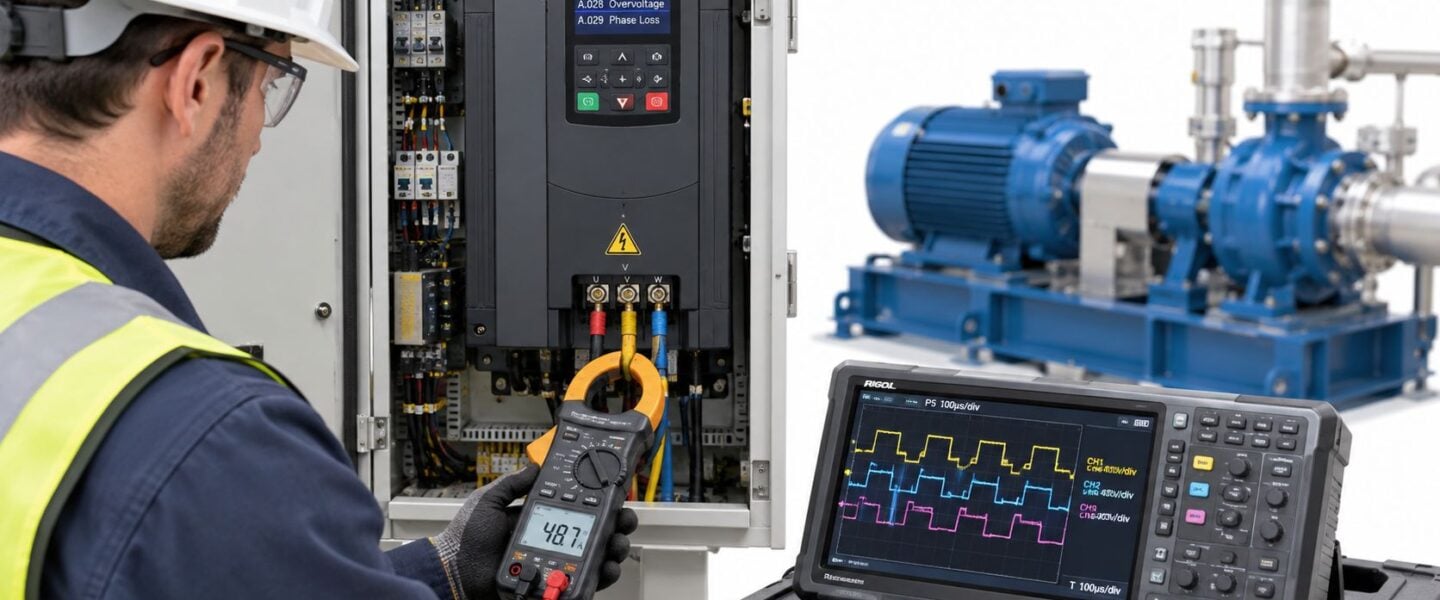
At 05:42, during a shift handover, a 75 kW variable frequency drive (VFD) on a cooling-water pump skid in a chemical plant trips on overcurrent. The pump supports a downstream reactor, and the production team estimates the outage at roughly $9,000 per hour. The night operator sees a red fault screen, reaches for reset, and waits for the motor to start again.
That reaction is understandable, but it can turn one trip into a damaged motor, failed output stage, or a longer outage. A VFD alarm usually identifies the symptom, not the cause. In a field engineer guide, about 60% of post-installation VFD faults were attributed to incorrect parameter settings rather than hardware failure, while overcurrent represented 35% to 45% of all VFD trips (field guidance on VFD troubleshooting). The practical response is a sequence, not a reset: capture evidence, isolate the system, test the supply and motor path, verify the configuration, and prove the corrective action under controlled conditions.
Table of Contents
- When the Drive Trips and the Shift Needs It Back
- Lock Out, Capture, and Read the Drive Before You Touch Anything
- Matching Fault Codes to the System That Actually Caused the Trip
- Electrical and Control Checks in the Right Order
- Instrumentation Tests That Separate Motor From Drive
- Root Causes That Keep Coming Back After the Reset
- Verify, Document, and Know When to Escalate
When the Drive Trips and the Shift Needs It Back
The first sixty seconds determine whether the team preserves useful evidence or loses it. The reliability technician confirms the trip on the HMI, records the exact fault code and timestamp, and notes whether the pump was starting, accelerating, running steadily, or stopping. The technician also checks the pump, coupling, motor, valves, and skid for obvious damage, abnormal noise, leakage, blockage, or signs that the driven equipment has seized.
The reset button stays untouched.
A cooling-water pump that trips on overcurrent might have incorrect motor data, an acceleration ramp that demands too much torque, a blocked impeller, a failing bearing, damaged output insulation, or an internal drive fault. A code such as OC narrows the search, but it doesn't tell the team which subsystem caused the current to rise. That distinction matters when the pump is process-critical and every restart attempt adds stress without improving the diagnosis.

The first response protects the investigation
The technician should preserve the drive display, fault history, operating values, and operator observations before power is removed. A useful log entry includes:
- Fault identity: Record the code exactly, including any suffix or operating-state detail.
- Event timing: Note when the trip occurred and what the pump was doing.
- Process context: Capture flow demand, valve position, suction and discharge conditions, and any recent process change.
- Physical condition: Check for mechanical binding, hot bearings, damaged cables, contaminated enclosures, and unusual sound.
- Restart decision: Document why the drive was or wasn't reset.
A systematic approach matters because field guidance reports that disciplined isolation with a megohmmeter, multimeter, and built-in diagnostics can resolve 90% of field failures without replacing the VFD (industrial VFD troubleshooting guidance). That doesn't mean every drive is healthy. It means replacement should be the conclusion of testing, not the opening move.
Treat the pump skid as a system
The pump, motor, cable, VFD, instrumentation, process piping, and control logic form one operating system. A pump can draw excessive current because the impeller is obstructed. A drive can report overcurrent because the motor parameters are wrong. A healthy motor can trip because a loose terminal creates voltage imbalance or because a control signal commands an abrupt acceleration.
A plant team can use a broader variable-speed-drive plant optimization approach to connect drive behavior with asset condition, process demand, and maintenance history. The immediate job remains narrower: identify what changed, isolate the fault path, and return the pump only after the cause has been cleared.
Lock Out, Capture, and Read the Drive Before You Touch Anything
A VFD, or variable frequency drive, converts incoming AC power into controlled-frequency power for a motor. Its DC bus is the internal energy link that stores electrical charge in capacitors after the incoming supply is disconnected. LOTO, or lockout/tagout, is the controlled process used to isolate hazardous energy, apply personal locks and tags, and verify that the equipment can't unexpectedly energize.
The safe sequence begins before anyone opens the cabinet or disconnects a motor lead. Site procedures, the drive manufacturer's instructions, and the electrical safety program govern the work. The DC bus can remain dangerous after isolation, so the technician must never treat a dark keypad as proof of zero energy.
Isolate and prove the energy state
- Open the disconnect. Isolate the VFD at the designated source, not only through a software stop command or local keypad.
- Apply personal LOTO. Each person working on the equipment applies a personal lock and tag according to site procedure.
- Test the tester. Confirm that the properly rated voltage tester works on a known live source before testing the isolated circuit.
- Verify the line side. Test the incoming terminals for absence of voltage using the approved method.
- Check the DC bus. Test the DC bus terminals with a properly rated instrument and follow the manufacturer's discharge time.
- Prove the instrument again. Recheck the tester on a known source after the measurement.
The technician shouldn't short the bus, bypass an interlock, or assume a timer has discharged the capacitors. Field guidance identifies safety isolation, fault capture, DC bus discharge verification, line conditions, grounding, and wiring integrity as the correct opening sequence (VFD safety and troubleshooting workflow).
Capture evidence during the discharge period
While the bus discharges, the team records the information that disappears after a reset or parameter change. A fault log stores recorded drive faults. Trip history adds operating context, such as current, frequency, temperature, or bus voltage, when the event occurred. A parameter set is the drive's stored configuration for the motor, ramps, limits, control mode, and protection functions.
The capture checklist should include:
- Photograph the keypad, HMI, cabinet condition, terminal area, and visible fault screen.
- Scroll through the stored history and save the available trips, timestamps, and operating values.
- Record motor nameplate voltage, current, frequency, speed, and connection details.
- Note ambient temperature, enclosure condition, fan operation, and operator comments.
- Download the parameter file if the drive supports export.
- Save the file with the asset number, date, and fault reference.
Practical rule: A reset removes symptoms from the screen. It doesn't restore the evidence that explains why the trip occurred.
A ten-minute capture phase often separates a one-trip correction from a recurring nuisance. The saved baseline also supports motor current signature analysis for fault detection when the team needs to compare electrical behavior with later condition-monitoring results.
Matching Fault Codes to the System That Actually Caused the Trip
Fault-code triage works best when the technician adds two questions to every alarm. When did the trip occur in the operating cycle, and which subsystem could create that electrical symptom? A power-up fault, acceleration fault, steady-run fault, and deceleration fault point toward different suspects.
Industrial troubleshooting guidance associates power-up faults with input-supply problems, acceleration faults with mechanical load or output-stage conditions, steady-run faults with thermal, motor, or cable problems, and deceleration faults with DC-bus overvoltage or braking-energy management (operating-phase fault guidance). That timing can rank the investigation before the cabinet is opened.
Build a ranked shortlist
Overcurrent and ground faults during startup raise suspicion of a jammed load, shorted output cable, winding insulation damage, or an incorrect motor configuration. An overvoltage event during deceleration makes the ramp, inertia, and regenerative energy path more relevant than the motor nameplate. Undervoltage and input phase loss require attention to the supply under load, not just a no-load voltage reading.
Overtemperature in a hot or contaminated cabinet points first to airflow, heatsink condition, fan operation, and loading. Communication loss points toward the control network, signal wiring, shielding, or configuration rather than the power stage. A motor overload that develops during steady operation can reflect process loading, pump condition, coupling problems, or a parameter mismatch.
| Fault Code / Family | When It Typically Trips | Most Likely Subsystem | First Check to Run |
|---|---|---|---|
| Overcurrent, OC | Startup or acceleration | Motor, cable, driven load, or parameters | Review motor data, ramp settings, fault context, and mechanical freedom |
| Ground fault, GF | Startup or under load | Output cable, motor insulation, or moisture | Isolate the output and test phase-to-ground insulation |
| DC bus overvoltage, OV | Deceleration or rapid load change | Braking path, inertia, or input supply | Review deceleration behavior and bus trend |
| Undervoltage, UV | Power-up or loaded acceleration | Incoming supply, phase loss, or connection | Measure all phases at the drive terminals under load |
| Overtemperature, OT | Extended operation | Cooling system, enclosure, or excessive load | Inspect fan, heatsink, airflow, ambient condition, and current |
| Communication fault | Command or control transition | PLC, network, control wiring, or settings | Check controller status, physical connections, and matching settings |
| Motor overload, OL | Sustained loaded operation | Motor, driven equipment, or process | Compare current with motor data and inspect the mechanical load |
| Output phase loss | Startup or operation | Terminal, cable, motor winding, or inverter stage | Check connections, phase currents, and winding balance |
The table is a triage tool, not a repair instruction. The code should produce a ranked list of tests. A drive replacement before those tests risks installing a second drive into the same failed motor, cable route, grounding system, or process condition.
A structured electrical fault detection program helps preserve that distinction by connecting fault events with measurements and asset history. For the pump skid, the most useful question isn't “Which drive failed?” It is “Which part of the pump system created the condition the drive detected?”
Electrical and Control Checks in the Right Order
Electrical troubleshooting becomes inefficient when technicians jump between input voltage, motor insulation, and control signals without an isolation strategy. The reliable order is line side, DC bus, motor side, then control wiring. Each stage either excludes a failure family or gives the next test a more precise target.
Start at the incoming terminals
The first measurement is a true RMS reading of all three phases at the VFD input terminals. Testing only at the panel can miss a loose termination, voltage drop, or heat-damaged connection between the panel and drive. The technician checks phase balance, voltage sag during acceleration, and harmonic distortion against the facility's power-quality requirements.
Line-voltage deviation greater than 5% is identified in field guidance as a contributor to failures and nuisance trips (field VFD troubleshooting checks). The team should also inspect fuses, disconnects, lugs, and conductors for discoloration or heat damage. A no-load reading that looks acceptable doesn't clear the supply if the fault appears only when the pump loads the feeder.
Protective-earth continuity comes next. The technician verifies the path from the drive chassis to the facility grounding grid with an approved fall-of-potential or clamp-on ground tester. The inspection should include paint between panels and backplates, loose bonding jumpers, and termination points that rely on mechanical contact rather than a deliberate bonding path.
Examine the DC bus without guessing
Once the cabinet is safe to access, the technician compares measured capacitor voltage with the drive display. A disagreement can indicate a sensing problem, measurement error, or DC-bus condition that needs specialist attention. The inspection also covers bulging or leaking capacitors, the pre-charge resistor, and the pre-charge contactor.
The pre-charge circuit limits the initial charging current into the DC-bus capacitors. A failed resistor or contactor can create power-up behavior that looks like a supply fault. The team records the result rather than changing components based solely on appearance.
Move from output conductors to the motor
The motor cable is isolated from the drive before insulation testing. A megohmmeter applies a controlled DC test voltage to evaluate insulation resistance phase-to-phase and phase-to-ground. Testing the cable separately from the motor helps locate the defect, while comparing motor-winding results with historical baseline shows whether condition has changed.
The technician then checks output terminals, motor terminals, gland seals, junction boxes, and cable routing. A loose connection, chemical contamination, moisture, or physical abrasion can create intermittent faults that a quick continuity test misses.
Finish with control wiring
Control wiring is checked after the power path is understood. Shielded twisted pairs should have a deliberate shield-termination strategy, sensitive signal wiring should remain separated from power conductors, and the 24 V DC supply should be clean at the drive terminals. Analog reference signals, permissives, run commands, feedback circuits, and network conductors each need a specific point-to-point check.
This order prevents instrumentation noise from being blamed for a motor fault and prevents a damaged motor cable from being mistaken for a failed controller.
Instrumentation Tests That Separate Motor From Drive
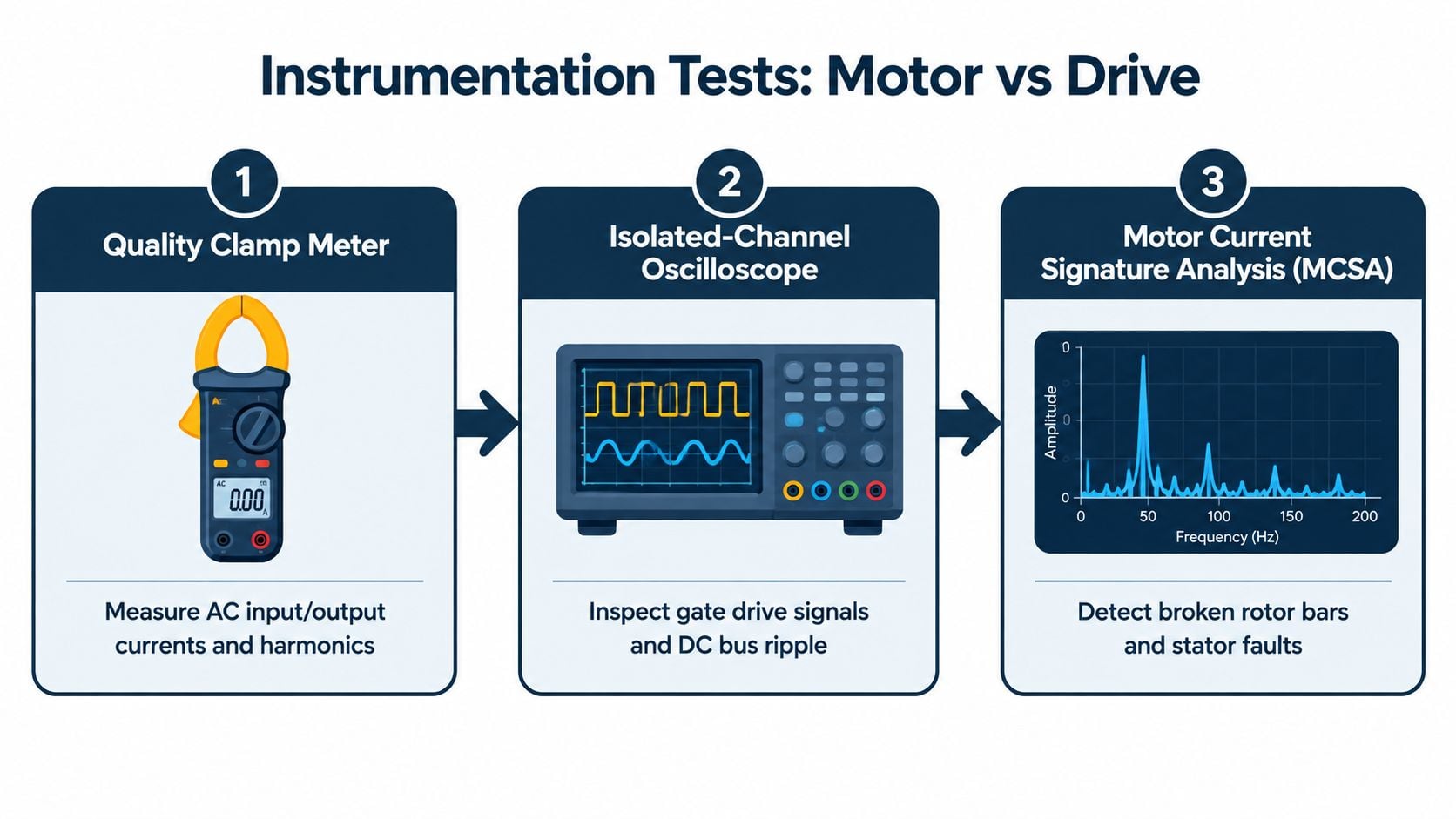
A drive keypad provides useful context, but it rarely proves the fault path. Three instruments add that proof: a quality clamp meter, an isolated-channel oscilloscope, and motor current signature analysis (MCSA). MCSA is a condition-monitoring method that examines motor current patterns for electrical and mechanical signatures.
Use current balance as an isolation test
The clamp meter starts with the DC bus in DC mode, using the measurement points and safety rating specified for the drive. It then measures each output phase in true RMS AC mode while the pump runs in a controlled state. Output current should remain balanced within 5% for the comparison described in the field workflow.
If one phase diverges, the investigation moves downstream toward the motor, coupling, cable, or driven load. Balanced output current doesn't prove the drive is healthy, but imbalance is a strong reason to stop treating the drive as the primary suspect. The technician records speed, process load, current, and temperature together because a single current value lacks operating context.
Use the oscilloscope for switching behavior
An isolated-channel oscilloscope allows the technician to inspect PWM, or pulse-width modulation, without creating an unsafe ground path through the instrument. The output waveform should be examined for abnormal ringing, switching irregularity, DC-bus ripple, and evidence of a failing power switch.
The test also captures line-to-line voltage at the motor terminals. Long cable effects, reflected waves, and dV/dt, the rate at which voltage changes over time, become visible here. PWM output creates high-frequency harmonics that can increase motor heating, particularly at low speed when the motor's own fan moves less air. Mitigation can include an inverter-duty motor, a dV/dt or sinewave filter, a lower carrier frequency, or forced external cooling (PWM motor-stress guidance).
Use MCSA for condition evidence
MCSA is most useful when the drive operates in a stable window with steady load. The analyst examines sideband patterns around the electrical supply frequency for broken rotor-bar indications and stator-current slot harmonics for air-gap eccentricity or related motor conditions.
NEMA MG 1 addresses VFD-fed motor stress by requiring motors rated 600 V or lower to withstand a 3,000 V, 0.1 microsecond spike at the motor terminals (NEMA MG 1 motor-stress guidance). That requirement doesn't eliminate cable or installation concerns. Long motor leads, reflected waves, and poor termination can still increase insulation stress and bearing-current risk.
A specialist motor insulation resistance testing process complements the live measurements by showing whether the motor and cable insulation can withstand continued service. The combination of current, waveform, and insulation evidence is far stronger than swapping the drive and waiting for the next trip.
Root Causes That Keep Coming Back After the Reset
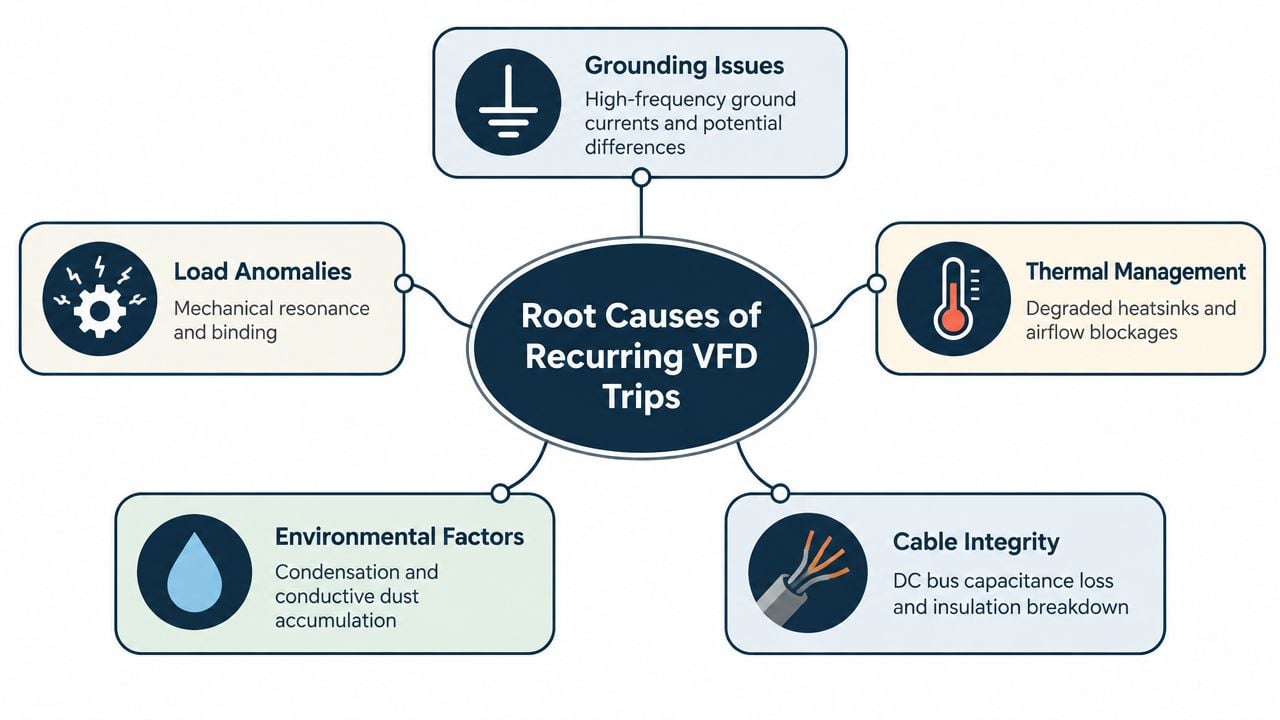
A reset that holds for an hour isn't a repair. It only proves that the fault condition wasn't active at that exact moment. Recurring VFD trips usually belong to one of five investigation families, and each family requires a different corrective action.
Grounding and EMC problems
Grounding and bonding faults often produce intermittent behavior. Daisy-chained grounds, paint between panels and backplates, and missing single-point references can create common-mode noise, which is unwanted high-frequency voltage shared across conductors and ground paths. The drive may interpret that noise as a current, feedback, or communication problem.
The corrective action is a physical inspection and measurement of the bonding network. The team removes accidental parallel paths, repairs loose connections, and confirms that shield terminations follow the engineered design rather than whatever arrangement was easiest during installation.
Electromagnetic compatibility (EMC) concerns the ability of equipment to operate without disturbing, or being disturbed by, other equipment. VFD-rated symmetrical cables, continuous shields, deliberate shield termination, and separation from sensitive signal wiring reduce nuisance trips and bearing-current exposure. A shield that is interrupted by a casual splice or grounded inconsistently can perform worse than an unshielded cable installed correctly.
Configuration and motor condition
Parameter mismatch remains a high-yield check after installation work, motor replacement, or control changes. Incorrect motor nameplate data, an unsuitable control mode, or a skipped auto-tune can make a healthy pump appear overloaded. The corrective action is to verify the stored parameter file against the actual motor and application, then perform the manufacturer's approved identification procedure where applicable.
Motor health requires a separate path. Degraded insulation, contaminated windings, and developing rotor-bar damage can remain hidden during light loading and appear only when the pump reaches process demand. Insulation testing, current comparison, vibration, and MCSA should be selected according to the suspected failure mode.
Thermal, environmental, and mechanical causes
Blocked heatsinks, failed fans, high ambient temperature, conductive dust, moisture, vibration, and a changed process load all deserve inspection. A pump may experience higher torque because of altered fluid properties, restricted flow, bearing wear, or a coupling problem. The drive reports the electrical consequence, while the mechanical inspection identifies the reason.
A recurring-trip record should map each event to one family and one corrective action:
- Grounding: Repair bonding, remove unintended ground paths, and verify continuity.
- EMC and cabling: Correct cable construction, shield termination, routing, and separation.
- Parameters: Validate motor data, control mode, ramps, limits, and auto-tune status.
- Motor health: Test insulation, current balance, vibration, and electrical signatures.
- Environment and load: Restore airflow, control contamination, inspect mechanics, and confirm process conditions.
Maintenance record standard: The corrective action should state what was measured, what failed the expected condition, what changed, and how the team verified the result.
The action belongs in the CMMS with the asset, fault family, evidence, and follow-up task. A formal root cause failure analysis process turns the fifth reset into a permanent change instead of another temporary restart.
Verify, Document, and Know When to Escalate
A successful restart is only the midpoint of the job. The pump must demonstrate stable behavior under controlled conditions before operations receives it back, and the record must preserve the reasoning for the next shift.
Prove the correction under load
The technician begins with the drive unloaded where the equipment design allows it, then ramps gradually to the intended setpoint. Current waveform, output balance, DC-bus ripple, speed feedback, and active alarms are compared with the captured baseline. The team doesn't accept a green HMI as proof of reliability.
The asset then runs under its normal operating condition while the technician monitors bearing temperature and vibration for 30 minutes. The duration is useful only when paired with the actual failure context. A pump that trips after thermal soak, process loading, or a specific control transition needs to be observed through that same condition.
Release criteria should be explicit:
- Electrical stability: No abnormal current imbalance, bus behavior, or recurring alarm.
- Mechanical response: No abnormal vibration, bearing temperature, coupling noise, or pump restriction.
- Control behavior: Commands, feedback, permissives, and interlocks operate as intended.
- Process performance: Flow, pressure, and reactor-support requirements remain within the operating target.
- Evidence quality: Measurements and parameter changes are saved with the work order.
Document the failure so it stays solved
The CMMS entry should capture the trip context, exact fault history, operating phase, measurements, suspected root cause, confirmed cause, corrective action, parameter changes, and verification results. Photographs, exported parameter files, waveform captures, insulation results, and current readings should be attached to the asset record when the system supports them.
That documentation prevents the next technician from repeating the same tests without learning from the first event. It also lets maintenance managers identify whether a fault belongs in a preventive task, a condition-monitoring route, a spare-parts decision, or a capital project.
Escalate at the right boundary
Some conditions exceed routine field troubleshooting. Escalation is appropriate for:
- IGBT module damage: Burn marks, abnormal switching, or a fault that persists with the motor path isolated.
- Encoder feedback loss: Especially after cable replacement or termination work.
- Regenerative DC-bus faults: Where braking energy, shared buses, or stopping requirements need engineering review.
- Firmware mismatch: Drive, communication module, or control-system versions that don't align.
- Repeated unexplained trips: Events that continue after supply, motor, cable, parameter, environmental, and mechanical checks.
Forge Reliability provides VFD reliability work that can include capacitor health assessment, thermal monitoring, power-quality analysis, and condition-monitoring support. For a cooling-water pump skid, a free reliability assessment can connect the trip history with electrical testing, motor condition, CMMS records, and a practical preventive or predictive-maintenance route.
A free reliability assessment from Forge Reliability can review a recurring VFD trip, its motor and cable path, power-quality conditions, parameter evidence, and maintenance history. Visit Forge Reliability to identify the highest-value diagnostic checks for the plant's critical drives and turn repeated resets into documented corrective actions.