A maintenance technician is walking past a stamping press when a faint hiss appears near a fitting downstream of the aftercooler. The sound is easy to miss under production noise, yet the compressor is loading more often, receiver pressure is harder to hold, and pneumatic actuators are beginning to respond inconsistently. The leak tag alone won't solve the problem. The plant needs a controlled process that connects detection, quantification, repair ownership, and verification.
Compressed air leak detection works best when treated as a closed-loop reliability control. A running survey identifies where air escapes, plant-level measurements show how much the system is losing, and disciplined repair governance ensures that findings become completed work rather than forgotten tags. The sections below follow that chain from survey preparation through verified closure.
Table of Contents
- Why Compressed Air Leak Detection Needs a Reliability Program
- Plan the Survey Before Equipment Enters the Plant
- Choose Detection Methods for Each Plant Condition
- Set Up, Calibrate, and Record Field Data
- Quantify Leak Rate and Energy Loss
- Prioritize Repairs and Sustain the Results
- Apply the Workflow and Verify the Outcome
Why Compressed Air Leak Detection Needs a Reliability Program
During a walk-down in a metal-stamping plant, a technician may find a leak that looks minor at the outlet of a filter-regulator-lubricator assembly. The practical consequence can be much larger. Continuous leakage makes the compressor load more often, increases specific energy use, accelerates wear on seals and bearings, and can contribute to pressure drops at distant pneumatic actuators.
Poorly maintained compressed-air systems commonly lose 20% to 30% of compressor output through leaks, while proactive detection and repair programs can reduce leakage to below 10%, according to U.S. Department of Energy-derived compressed-air efficiency guidance. Those losses affect more than the utility bill. Pressure instability can slow tools, interrupt clamping, and create unreliable actuation. In cold conditions, increased air movement and moisture-management demands can also contribute to frozen lines where drainage and dryer performance are already marginal.
Detection and quantification serve different purposes
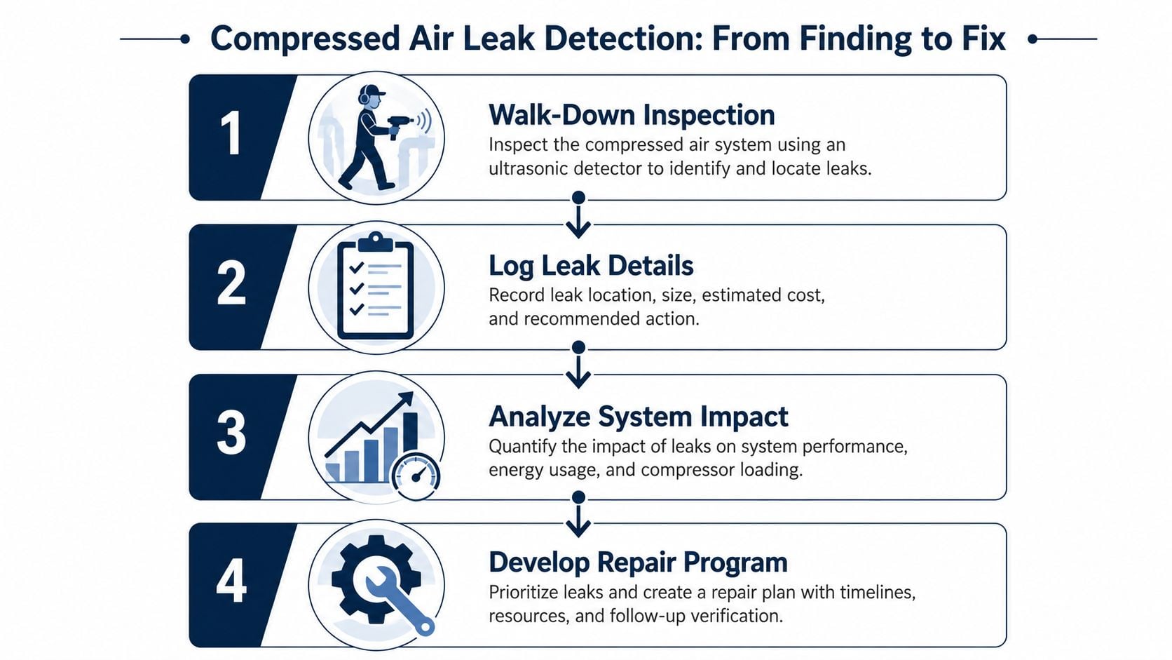
A handheld ultrasonic instrument is valuable for localization, meaning it helps a technician find the fitting, coupling, valve, hose, or drain point where turbulent air is escaping. It doesn't, by itself, provide a defensible plant-wide loss figure. For system-level quantification, compressor duty-cycle analysis, totalizer flow data, or controlled no-load testing provides stronger evidence about the total leakage burden.
That distinction changes how the maintenance team manages the work. A detector reading should support a tagged finding, not stand alone as the financial case. The record also needs line pressure, suspected orifice size, equipment criticality, accessibility, and the operating state under which the reading was taken.
Practical rule: Treat every leak tag as the beginning of a work order and every repair as incomplete until a follow-up measurement confirms closure.
A mature program also needs clear roles. Operations controls production conditions and access, maintenance owns repair execution, engineering validates system impact, and safety defines acceptable exposure. Teams that are formalizing those responsibilities may find a useful reference in plant maintenance roles at Intech Corporation. For a broader maintenance structure, the 12-month reliability program roadmap provides a framework for connecting condition data with planning and accountability.
Plan the Survey Before Equipment Enters the Plant
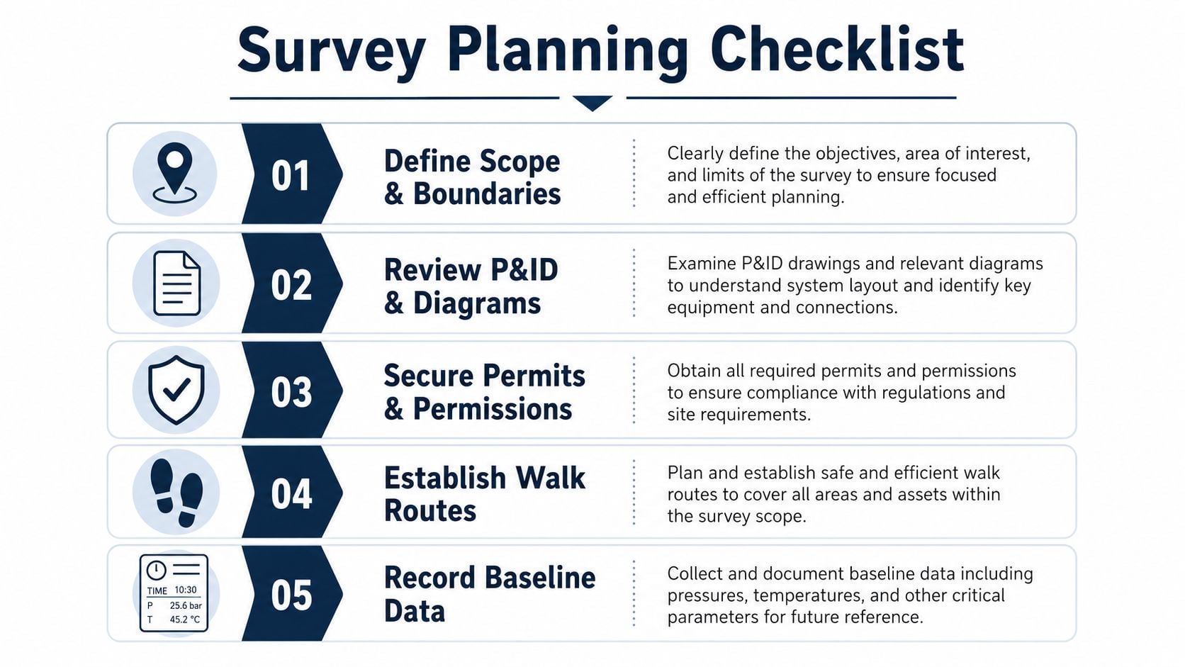
A reliable survey starts with a boundary, not a detector. The survey leader should mark the compressors, aftercoolers, dryers, receivers, filters, distribution headers, branch drops, point-of-use equipment, drains, and temporary connections included in the work. A current P&ID, or piping and instrumentation diagram, and a single-line air diagram should be reviewed before routes are assigned.
The planning meeting should settle four questions:
- What is included: Identify production areas, utility rooms, roof-level headers, maintenance shops, and isolated branches.
- What is excluded: Document inaccessible equipment, out-of-service lines, and areas requiring a separate permit.
- Who controls access: Name the operations contact, maintenance lead, safety representative, and survey coordinator.
- What operating state is required: Record whether the survey will run under normal production, reduced load, or a controlled shutdown.
Capture the operating baseline
Detector results only make sense when paired with plant conditions. Before the walk-down, the team should capture compressor start and stop times, receiver pressure trends, dryer dew point, ambient temperature, production schedule, and any energized equipment that can't be isolated.
The baseline should also identify operating changes likely to distort the findings. A food-processing line may be washing down while a survey is in progress. A press shop may be running only one shift. A chemical plant may have a normally closed branch temporarily open for maintenance. These details belong in the survey record because they affect both leak visibility and later comparison.
Define safety controls and stop-work conditions
Compressed air remains hazardous even when the leak is small. The team should confirm required PPE, hearing-protection zones, lockout and tagout points, hot-work permit requirements, high-access controls, and safe approach distances. A survey must stop when a line is unstable, a fitting is moving, a confined-space entry would be required, or isolation cannot be verified.
The field kit should include:
- Ultrasonic detector: Use the appropriate transducer and contact probe for airborne or structure-borne signals.
- Tagging materials: Assign a unique ID that can follow the finding into the CMMS.
- Pressure instruments: Carry a manometer or approved pressure gauge for local confirmation.
- Location tools: Use a distance meter, plant drawing, and consistent location strings.
- Records: Prepare paper or mobile data sheets that can be consolidated into one auditable dataset.
The pre-survey meeting should end with a route map, contact list, permit status, baseline timestamp, and escalation path for critical findings. That preparation prevents technicians from collecting isolated acoustic observations that operations can't interpret later.
Choose Detection Methods for Each Plant Condition
No detection method is universally reliable. The right choice depends on whether the system is running, whether the branch can be isolated, how noisy the area is, and whether the decision requires a location or a plant-level loss estimate.
Ultrasonic detection is usually effective on an operating compressed-air system because escaping air generates high-frequency turbulence. Guidance commonly places detectable leak ultrasound in the 25 to 150 kHz band, which is outside normal operator hearing but accessible to handheld instruments and acoustic imaging systems, as described in this compressed-air leak detection audit guide. The method is fast and nonintrusive, but readings depend on distance, pressure, background noise, surface reflections, and technician technique.
Acoustic imaging adds spatial context. A camera-based system can screen a noisy header run or high-bay pipe rack from a safer distance and help distinguish a likely leak location from surrounding machinery noise. It can accelerate coverage, but the image still requires confirmation under known pressure and a repair record that identifies the actual component.
Soap solution remains useful for close confirmation on accessible fittings, especially during a planned outage. It is inexpensive and visually clear, but it requires physical access, can create housekeeping concerns, and isn't suitable for every energized or raised location. A commercial ultrasonic device specification states that certain instruments can identify leaks smaller than 0.1 mm, with recommended pressure conditions varying by leak size, illustrating why pressure and instrument capability must be recorded rather than assumed. The specification is documented by this ultrasonic leak detector manufacturer reference.
Pressure-decay testing is different. It isolates a receiver or branch, closes known outlets, and observes pressure behavior over a controlled interval. It can verify branch integrity, but an undocumented valve passing internally or an active actuator can invalidate the result.
Flow metering is the strongest option for establishing a whole-plant baseline. It measures the supply required to maintain the system under defined conditions, while localization methods identify individual repair targets. The methods should be selected by decision role, as shown below.
| Method | Best Operating Condition | Primary Decision Role |
|---|---|---|
| Ultrasonic detection | Running plant with accessible or moderately difficult-to-access components | Locate and rank individual leaks |
| Acoustic imaging | Noisy production floor, high-bay routing, or broad header screening | Screen large areas and guide close inspection |
| Soap-bubble or visual inspection | Depressurized or safely accessible components during maintenance | Confirm suspected point leaks |
| Pressure decay | Isolated branch, receiver, or header with controlled boundaries | Verify integrity of a defined section |
| Flow metering | Stable plant operation or controlled no-load test | Quantify total system leakage |
| Contact-probe inspection | Suspected structure-borne transmission through piping or fittings | Separate component vibration from airborne leak signals |
For teams extending ultrasound into broader condition monitoring, acoustic monitoring for industrial reliability provides relevant program context. The key decision is simple: use localization data to find work, and use pressure or flow data to defend the size of the work.
Set Up, Calibrate, and Record Field Data
The detector should be treated as a measurement instrument, not a listening aid. Before each shift, the survey team should charge the battery, install the correct transducer, inspect the probe, and verify response against a controlled leak source or known orifice at regulated pressure. The purpose isn't to create laboratory precision. It is to confirm that the instrument responds consistently before field conditions introduce uncertainty.
The expected frequency range should also be checked. Turbulent compressed-air leaks are commonly surveyed in the 20 to 80 kHz range, depending on the instrument and application. The technician should establish a repeatable inspection distance, record the background reading away from the suspected leak, and note whether nearby machines are operating.
Make every finding auditable
A finding that says “leak near press three” won't support repair planning. The record should identify the exact component and the conditions under which it was detected.
| Field | Data Captured | Purpose |
|---|---|---|
| Asset ID | Equipment or branch identifier | Connect the finding to the asset hierarchy |
| Location string | Area, line, elevation, and component position | Let another technician find it without the original surveyor |
| Line pressure | Local pressure at inspection | Provide context for leak severity |
| Ambient temperature | Temperature at the time of inspection | Explain changes in signal behavior and operating state |
| Signal reading | Detector response and background comparison | Support consistent ranking |
| Distance | Probe or camera distance from the target | Make readings more comparable |
| Suspect fitting type | Coupling, valve, hose, drain, FRL, or threaded joint | Guide parts planning and failure analysis |
| Photograph | Component and surrounding reference points | Preserve visual evidence |
| Severity class | Agreed priority code | Drive CMMS scheduling and escalation |
| Accessibility code | Safe access, elevated access, isolation required, or restricted | Estimate execution difficulty |
Teams can use a structured ultrasound testing equipment resource when defining an instrument strategy, but the field process matters more than the device category alone.
Control measurement bias
A high detector response doesn't automatically mean a high flow loss. A nearby vent, pneumatic exhaust, steam source, or reflective metal surface can create a misleading signal. The technician should move toward the source, shield the probe where practical, compare readings from multiple angles, and confirm the exact fitting before assigning a severity class.
The survey database should use fixed codes for severity, accessibility, operating state, and verification status. A single dataset prevents duplicate tags and allows the same record to feed a leak-quantification worksheet, a CMMS work order, and the post-repair verification log.
Quantify Leak Rate and Energy Loss
Leak economics require two separate calculations. The first estimates the impact of an individual point leak. The second measures the total loss from the plant or a defined system boundary. Confusing those levels is one of the fastest ways to overstate savings or approve repairs on weak evidence.
At the point level, the team can use an orifice-style estimate based on line pressure and an estimated opening diameter. Ultrasonic conversion tables may help translate signal characteristics into approximate flow, but background noise, distance, surface reflections, and operator technique affect the result. A 1/4-inch-equivalent leak at 100 psig has been estimated at about $8,382 per year in electricity cost at $0.05 per kWh under continuous operation, while 1/8-inch and 1/16-inch equivalents are commonly benchmarked at about $2,095 and $523 respectively in the same DOE-derived guidance, available in this compressed-air leak cost reference.
Those benchmarks are prioritization aids, not invoices. The actual value depends on pressure, runtime, compressor specific power, motor efficiency, control mode, electricity rate, and whether the repair changes compressor loading.
Establish the plant loss pool
For the system-level calculation, use a flow totalizer or a controlled no-load test. The plant can run compressors while production equipment is vented or isolated, then measure the air required to maintain pressure within a defined boundary. The resulting leakage can be expressed as a portion of generated air, with the test conditions documented so later surveys remain comparable.
The financial worksheet should include:
| Input | Formula or Source | Example Value |
|---|---|---|
| Point leak estimate | Orifice estimate or ultrasonic conversion table | Enter measured estimate |
| Total system flow | Totalizer or controlled no-load test | Enter measured value |
| Compressor specific power | Compressor performance data | Enter site value |
| Motor efficiency | Motor or electrical test data | Enter site value |
| Operating hours | Production and compressor runtime records | Enter site value |
| Annual energy use | Air-loss flow converted through specific power and runtime | Calculate from site inputs |
| Electricity cost | Annual kWh multiplied by plant tariff | Calculate from site tariff |
| Repair value | Avoided energy cost compared with parts, labor, and downtime exposure | Use approved work estimate |
The plant optimization guidance for air compressors is relevant when connecting leak results with compressor controls and broader utility performance. A defensible repair decision compares estimated annual cost with repair cost, access requirements, and production risk. Detector readings identify candidates. Plant measurements establish the total opportunity.
Prioritize Repairs and Sustain the Results
A repair backlog becomes useful only when it reflects business risk. Ranking leaks by acoustic intensity alone can push a large but noncritical loss ahead of a smaller leak feeding a safety interlock, a packaging clamp, or a process-control actuator. The repair matrix should combine leak magnitude, equipment criticality, accessibility, and shutdown exposure.
Build the repair queue
A critical leak should receive a break-in job plan when continued leakage threatens production, product quality, or safe machine function. An accessible leak with moderate energy impact may be bundled into the next maintenance route. A benign leak on a low-criticality branch can be scheduled for the next planned shutdown, provided the condition is documented and monitored.
The repair record should include:
- Evidence: Attach the photograph, detector reading, pressure, location string, and operating state.
- Scope: Describe the suspected failure mode, such as a damaged hose, loose threaded joint, failed coupling seal, or leaking drain.
- Parts: Identify replacement seals, couplings, tubing, valves, or support hardware before scheduling.
- Ownership: Assign one repair owner and one verification owner.
- Value: Include the estimated energy impact and the consequence of delaying the work.
- Failure learning: Require a root-cause follow-up when the same fitting type repeatedly leaks.
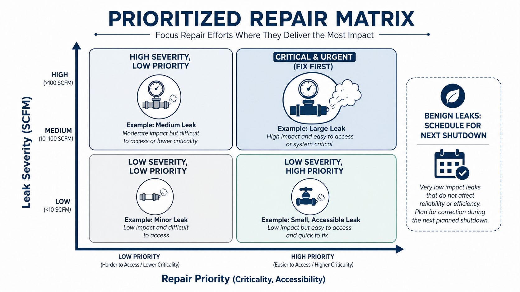
Every tag should become a corrective maintenance item in the CMMS, or computerized maintenance management system. The work order should retain the original measurement, repair action, parts used, completion date, and post-repair result. That history helps planners distinguish isolated workmanship problems from recurring design weaknesses in couplings, FRLs, hoses, supports, or drain arrangements.
Verify closure instead of trusting completion status
A closed work order doesn't prove that the leak is gone. After repair, the technician should repeat the inspection under comparable pressure and operating conditions. A zero or background-level signal should be recorded, along with a new photograph where access allows. If the signal remains, the work order should reopen rather than being marked complete.
Recurring leaks require a different response. The reliability team should examine installation torque, vibration, hose routing, pipe support, thermal movement, chemical exposure, and component selection. Routine resurveying can be supplemented by flow trend alarms, branch ultrasonic meters, or fixed acoustic sensors on critical headers. The objective is to trigger investigation when leakage returns, not wait for an annual walk-down.
Closure standard: A repair is complete only when the component is corrected, the evidence is updated, and the post-repair measurement confirms the intended result.
For plants with competing maintenance demands, resource allocation optimization can help place leak repairs within a broader criticality-based work plan. The program should track leak rate, repair closure time, repeat-leak percentage, overdue critical findings, and verified energy impact. Those measures turn compressed air leak detection into a managed reliability process.
Apply the Workflow and Verify the Outcome
A 250,000-square-foot metal-stamping plant runs three 200 hp compressors at 110 psig. Over one quarter, the team defines system boundaries, reviews the air diagram, completes a mixed ultrasonic survey, uses pressure-decay verification on the header, captures standardized field data, measures the plant-level flow-meter difference, and ranks CMMS tickets by severity and criticality.
The program tags 142 leaks and repairs 118. Residual compressor unload cycling falls from 38% to 14%, and verified annual energy savings reach $61,400 against a program cost of $14,900.
| Metric | Baseline | Post-Program | Change |
|---|---|---|---|
| Leaks tagged | Not established | 142 identified | New controlled inventory |
| Leaks repaired | Not established | 118 repaired | Closed through CMMS |
| Compressor unload cycling | 38% | 14% | Reduced by 24 percentage points |
| Annual energy savings | $0 verified | $61,400 | $61,400 verified |
| Program cost | $0 | $14,900 | $14,900 investment |
| Verification interval | Not established | 30-day resurvey | Closed-loop confirmation |
Survey drift still needs troubleshooting. Background noise can mask signals, simultaneous production loads can distort flow readings, and undocumented isolation points can create false pressure-decay passes. A 30-day resurvey confirms whether closed tickets remain closed and identifies repeat failures before they become production problems.
Forge Reliability provides ultrasonic compressed-air leak detection, condition monitoring, CMMS governance, and plant optimization support for industrial teams that need a defensible reliability workflow. Visit Forge Reliability to request a free reliability assessment and benchmark the plant's leak program from survey preparation through verified repair closure.