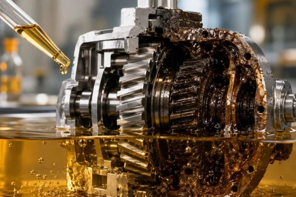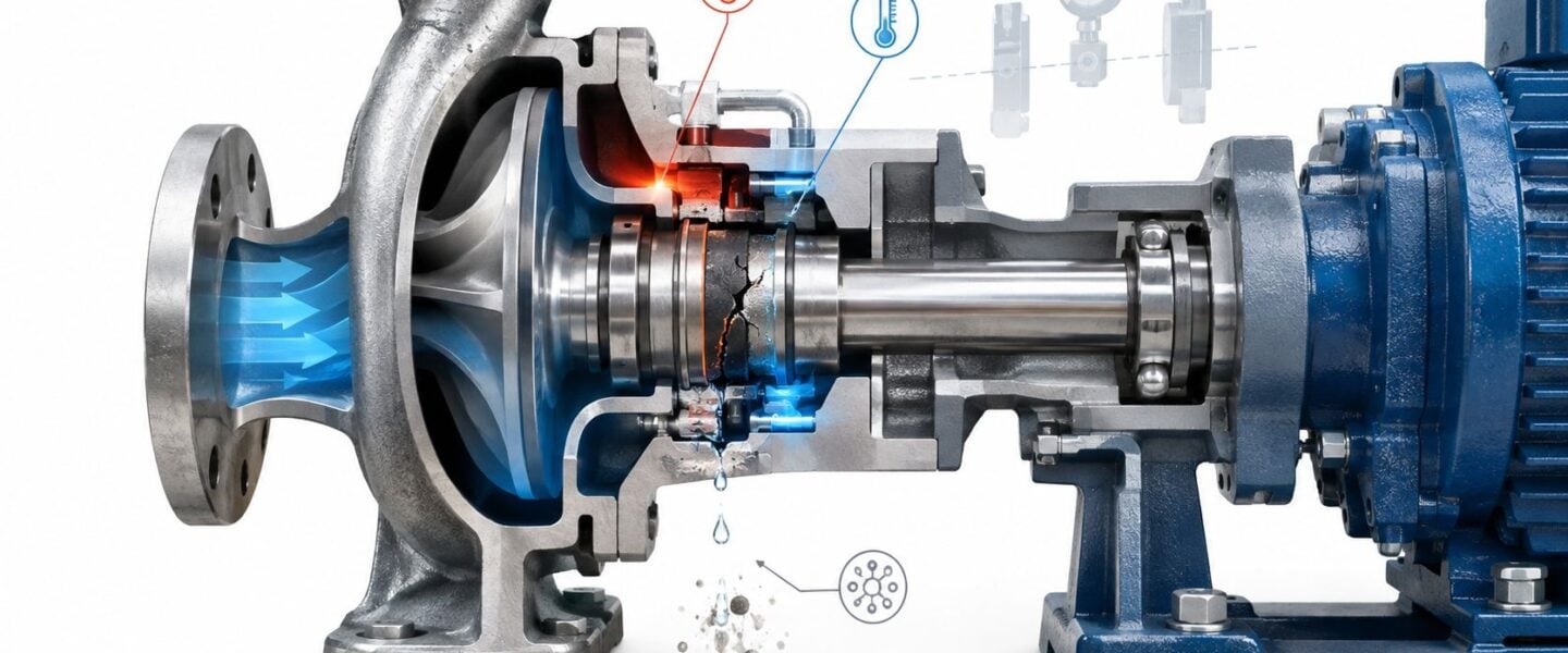
At 3 a.m., the alarm isn't usually labeled pump seal failure causes. It reads “high leakage,” “containment loss,” or “process pump unavailable.” The maintenance crew isolates the horizontal end-suction pump, changes the seal, cleans the drip pan, and returns the asset to service. Weeks later, the same sequence repeats because the failed seal was treated as the problem instead of evidence of a wider rotating-equipment issue.
Mechanical seals commonly fail after dry running, cavitation, misalignment, contamination, poor installation, unstable hydraulics, or inadequate flush control have already damaged the sealing interface. In the European Sealing Association dataset summarized in its reliability document, seals appeared in about 60.4% of 3,500 recorded pump failures across 18 end users, while premature seal failures were attributed to 49% operations, 28% maintenance, and 23% engineering. The practical lesson is direct: the seal often becomes the final visible failure point in a system that has been operating outside its intended envelope.
Table of Contents
- The Hidden Cost of Repeat Seal Leaks on the Plant Floor
- How Mechanical Seals and Packing Actually Work
- The Seven Root Cause Families Behind Seal Failure
- Diagnostic Signatures and Inspection Techniques
- A Chemical Transfer Pump Case Study
- Short-Term Repairs and Permanent Fixes
- Monitoring, RCM, and Closing the Reliability Loop
The Hidden Cost of Repeat Seal Leaks on the Plant Floor
A recurring seal leak on an ANSI process pump creates more than a spare-parts transaction. The shift team loses production during isolation and repair, maintenance consumes another seal and lubricant, operators manage the immediate containment issue, and environmental staff may need to clean the drip pan and document the release. If the service involves hazardous or regulated chemicals, the leak can also trigger a formal process safety review and additional corrective-action paperwork.
The cost stack becomes especially painful when the pump is a bottleneck. A chemical transfer pump may support a batch, feed a reactor, circulate a heat-transfer fluid, or maintain a utility loop. Its mechanical seal is a small component, but its failure can stop the entire process. A recurring seal problem can create an annualized burden of $50,000 to $250,000 per recurring seal, depending on service, when downtime, labor, materials, cleanup, and production disruption are considered.
Why replacement alone doesn't work
The usual response is predictable. A technician installs an identical seal, checks for visible leakage, and releases the pump. That action restores containment temporarily, but it doesn't answer the questions that determine whether the next seal will survive:
- Was the pump starved during startup?
- Did the suction condition allow vapor formation?
- Was flush flow measured, or only assumed?
- Did pipe strain distort the casing or gland?
- Was the shaft aligned and within runout tolerance?
- Did the pump operate far from its best efficiency point?
- Did the selected face and elastomer materials match the actual fluid and temperature?
A failure investigation should separate the symptom, the mechanism, and the underlying cause. A glazed face is a symptom. Loss of lubrication is a mechanism. A blocked flush orifice, poor startup sequence, or unsuitable support system may be the underlying cause.
Practical rule: If the same pump consumes replacement seals on a repeating cycle, the maintenance team should stop treating the work as routine repair and open a structured root cause investigation.
This is why a plant's maintenance cost reduction program should include seal failures as reliability events, not just corrective work orders. The leak is the visible tip of an operating-envelope problem involving hydraulics, installation, heat removal, shaft movement, or support-system reliability.
How Mechanical Seals and Packing Actually Work
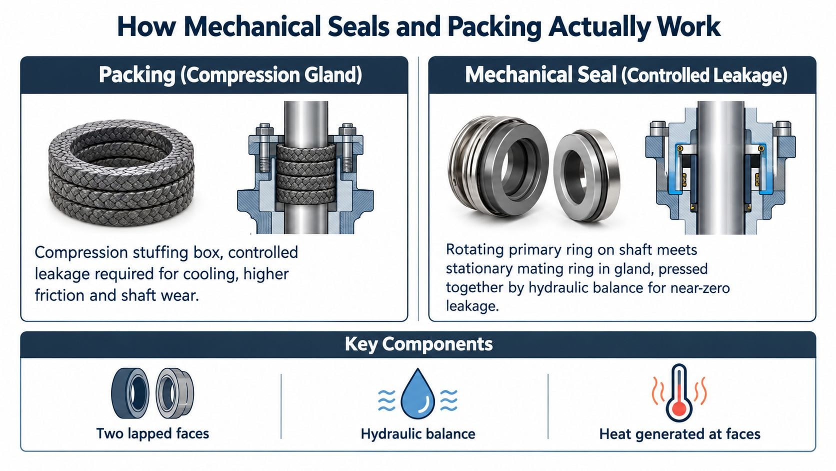
A mechanical seal is a controlled-leakage device installed where a rotating shaft passes through a pump casing. Its primary sealing interface consists of two precisely lapped faces. One face rotates with the shaft, while the stationary mating face is held in the gland. Springs, bellows, and hydraulic pressure keep the faces together, but normal operation depends on a very thin fluid film between them.
That film provides lubrication and removes heat. Fluid dynamics maintain the separation, so the faces shouldn't run as dry sliding surfaces. When the film collapses, friction rises, temperature increases, and the faces can distort, wear, crack, or glaze. A technical review of mechanical seal failures identifies dry running, misalignment, vibration, cavitation, incorrect selection, poor installation, and contamination as major triggers that destabilize the face interface (technical literature on seal failure mechanisms).
Packing accepts leakage by design
Compression packing works differently. Braided rings sit around the shaft or sleeve inside a stuffing box, and gland compression pushes the packing against the sleeve and housing. A controlled amount of leakage is necessary because the liquid cools and lubricates the packing. Excessive tightening may reduce visible leakage briefly, but it also increases friction, shaft wear, heat, and power consumption.
A mechanical seal aims for near-zero visible leakage, while packing requires managed leakage. Confusing those operating philosophies leads to poor maintenance decisions. A packing gland that's dry and hot may be over-tightened. A mechanical seal that drips steadily may be losing face control or suffering from damaged secondary seals.
Support hardware determines seal survival
The seal faces receive most of the attention, but the surrounding hardware controls their environment:
- Gland plate: Holds the stationary face and must seat without distortion. Uneven bolting or pipe strain can tilt the face.
- Set screws and drive pins: Transfer torque to the rotating assembly or prevent stationary rotation, depending on the seal design. Incorrect placement or torque can damage the sleeve or allow movement.
- O-rings and gaskets: Seal static gaps. Chemical attack, heat, extrusion, or compression set can create leakage even when the faces remain intact.
- Flush and quench connections: Supply cooling, lubrication, cleaning, or vapor control. A blocked line can turn a properly selected seal into a thermal failure.
- API flush plans: Plans 11, 13, 14, 23, 32, 52, and 53 provide different methods for recirculation, external flushing, cooling, quenching, or pressurized barrier-fluid control.
A pump's centrifugal pump reliability guidance should therefore assess the seal, gland, sleeve, flush system, shaft, bearings, coupling, and hydraulic duty as one assembly.
The Seven Root Cause Families Behind Seal Failure
Failure investigations often reveal several contributors, but the mechanisms usually fit into a small group of recurring families. The European Sealing Association's root-cause distribution reinforces the need to examine operations, maintenance, and engineering together rather than assigning every event to seal wear.
Installation and alignment
Improper installation can damage a seal before the pump reaches operating temperature. Common examples include incorrect set dimension, uneven gland tightening, excessive or insufficient set-screw torque, damaged O-rings, contaminated faces, distorted gland plates, and angular misalignment beyond 0.05 inches per inch. Alignment errors impose cyclic movement on the face pair, while poor assembly can prevent the seal from establishing uniform loading.
Hydraulic instability
Dry running, vaporization at the seal face, inadequate net positive suction head, suction recirculation, closed valves, vapor lock, and operation away from the pump's best efficiency point all belong here. Off-BEP operation raises hydraulic radial loads and shaft deflection, which transfers movement into the seal faces. A reliability study of pump seal failures links off-BEP operation with repeated seal problems because the pump's hydraulic condition directly affects shaft stability.
Lubrication and flush starvation
The face film depends on a stable supply of compatible fluid and sufficient heat removal. If flush pressure falls below seal chamber pressure, process fluid can enter the flush system or the intended cooling flow can disappear. A deadheaded pump, blocked orifice, closed isolation valve, or uncommissioned flush line can collapse the boundary film and create rapid heat generation.
Thermal overload
Every seal has a pressure-velocity and temperature operating envelope. Continuous duty above the seal's PV limit, meaning the combined pressure and sliding velocity loading the faces can tolerate, increases heat faster than the system can remove it. A field-data study reported graphite stationary-ring fracture caused by excessively high inlet oil temperature, demonstrating that thermal overload can create a brittle fracture rather than gradual wear (field study of mechanical seal failure).
Contamination
Abrasive particles create three-body wear between the faces. Crystallizing chemicals can wedge the faces open, polymer deposits can restrict spring movement, and solids can score sleeves and damage elastomers. The correct countermeasure depends on the contaminant. A cleaner flush, separator, filter, or different face material may be more effective than installing a heavier seal.
Shaft movement
Shaft runout above 0.002 inches total indicated runout can destabilize the face pair. Excessive deflection, bearing clearance, sleeve wear, coupling problems, and soft foot all increase movement at the seal. When a seal and bearing fail together, the bearing or shaft-support problem deserves investigation rather than assuming two unrelated failures.
System design
Oversized impellers, parallel pumps fighting each other, insufficient minimum-flow protection, missing thermal relief, poor suction piping, and an unsuitable seal chamber design can create conditions no replacement seal can overcome. The engineering review should test actual flow, pressure, temperature, startup, shutdown, and upset conditions against the pump and seal design basis.
| Root Cause Family | Primary Mechanism | Typical Seal-Side Damage |
|---|---|---|
| Installation and alignment | Uneven face loading and cyclic movement | Uneven wear track, damaged O-rings, distorted faces |
| Hydraulic instability | Loss of stable pressure and fluid film | Heat checking, face opening, leakage |
| Lubrication and flush starvation | Inadequate cooling or boundary-film collapse | Glazing, blistering, discoloration |
| Thermal overload | Heat generation exceeds rejection capacity | Cracked faces, hardened elastomers, distortion |
| Contamination | Abrasive or deposited material disrupts the interface | Scoring, pitting, clogged springs |
| Shaft movement | Runout and deflection force faces open and closed | Fretting, wide wear track, chipped edges |
| System design | Pump operates outside the intended envelope | Repeated failure despite correct installation |
A structured root cause failure analysis process keeps these families connected to evidence, corrective actions, and verification.
Diagnostic Signatures and Inspection Techniques
A failed seal should be preserved as evidence. The technician should photograph the assembly before cleaning, label the rotating and stationary components, record the process conditions, and keep the flush hardware with the seal. Washing away deposits or discarding a cracked face before inspection can remove the only evidence that distinguishes dry running from contamination or vibration.
Teardown evidence
A glazed face often indicates heat and altered surface finish. Heat checking, frosting, discoloration, blistering, and localized hot spots point toward inadequate lubrication or thermal control. Pitting can indicate flashing or vapor formation, while particulate imprints and circumferential scoring suggest contamination.
Secondary components tell a different story. Flattened or hardened O-rings indicate heat exposure or compression set. Swollen or gummy elastomers suggest chemical incompatibility. Springs packed with solids point toward contamination or an unsuitable flush arrangement. Sleeve grooves, fretting, and a wide wear track require dimensional checks rather than another seal replacement.
Online condition monitoring
The most useful monitoring method depends on the suspected mechanism:
- Thermal imaging: Compare seal-chamber, flush-inlet, bearing-housing, and nearby process temperatures. A rising seal temperature with falling flush flow supports a cooling or lubrication problem.
- Vibration analysis: Review 1x running speed, harmonics, vane-pass frequencies, and bearing-housing demodulation. Misalignment, looseness, cavitation, and shaft movement can leave different spectral and time-waveform patterns.
- Ultrasound: Listen at the seal chamber and suction piping for vapor formation, turbulent leakage, or cavitation-related noise.
- Flush-fluid sampling: Check for contamination, solids, chemical attack, and degradation of the supporting fluid.
- Dimensional inspection: Measure shaft or sleeve runout, gland squareness, shaft fit, face flatness, and component wear against the manufacturer's tolerances.
A worked example shows how evidence should converge. A scorched seal face, raised flush-inlet temperature, and a high-frequency vibration peak near 2x running speed point toward inadequate flush flow combined with shaft or coupling movement. The hot face identifies the thermal consequence, the flush temperature supports poor heat removal, and the vibration peak indicates that the interface is also being disturbed mechanically. The corrective action should verify flow, pressure, orifice condition, alignment, and shaft movement before selecting a different seal.
| Root Cause Family | Visual / Dimensional Signature | Monitoring Technique | Confirmation Method |
|---|---|---|---|
| Dry running | Heat checks, blistering, severe discoloration | Thermography and ultrasound | Verify suction level, valve position, and startup sequence |
| Misalignment | Uneven wear track and sleeve fretting | Vibration at 1x and 2x components | Laser alignment and soft-foot checks |
| Cavitation | Pitting, chipped edges, vapor noise | Ultrasound and vibration | Confirm suction pressure and available NPSH |
| Flush starvation | Scorched faces and hot O-rings | Flush pressure, flow, and temperature trends | Inspect valves, tubing, orifice, and cooler |
| Contamination | Scoring, imprints, packed springs | Fluid sampling and ultrasound | Identify solids and inspect filtration or separation |
| Shaft movement | Wide track and eccentric wear | Vibration and phase analysis | Measure runout, deflection, bearings, and sleeve condition |
Teams responsible for containment can use ultrasonic leak detection guidance as part of the inspection route, but ultrasound shouldn't replace teardown evidence or hydraulic verification.
A Chemical Transfer Pump Case Study
A centrifugal chemical transfer pump in hot hydrocarbon service experienced three seal failures over fourteen months. The equipment was an ANSI process pump with a single mechanical seal and a Plan 32 flush, rated for 120 gallons per minute at 1,450 revolutions per minute. Historical seal MTBF, or mean time between failures, was around four months, which made the asset a recurring bad actor rather than a random event.
The first failure produced the standard response. The operator replaced the seal and returned the pump to service, but nobody recorded the face condition, flush flow, process temperature, or startup state. Without those observations, the replacement removed the evidence and left the failure mechanism unknown.
At the second failure, the technician found glazing and a hot spot at 7 o'clock on the rotating face. The gland load was adjusted and the seal was reinstalled. That action changed the symptom temporarily, but it didn't establish whether the face had overheated because of poor flush, misalignment, vapor formation, or process instability.
The third failure exposed the mechanism
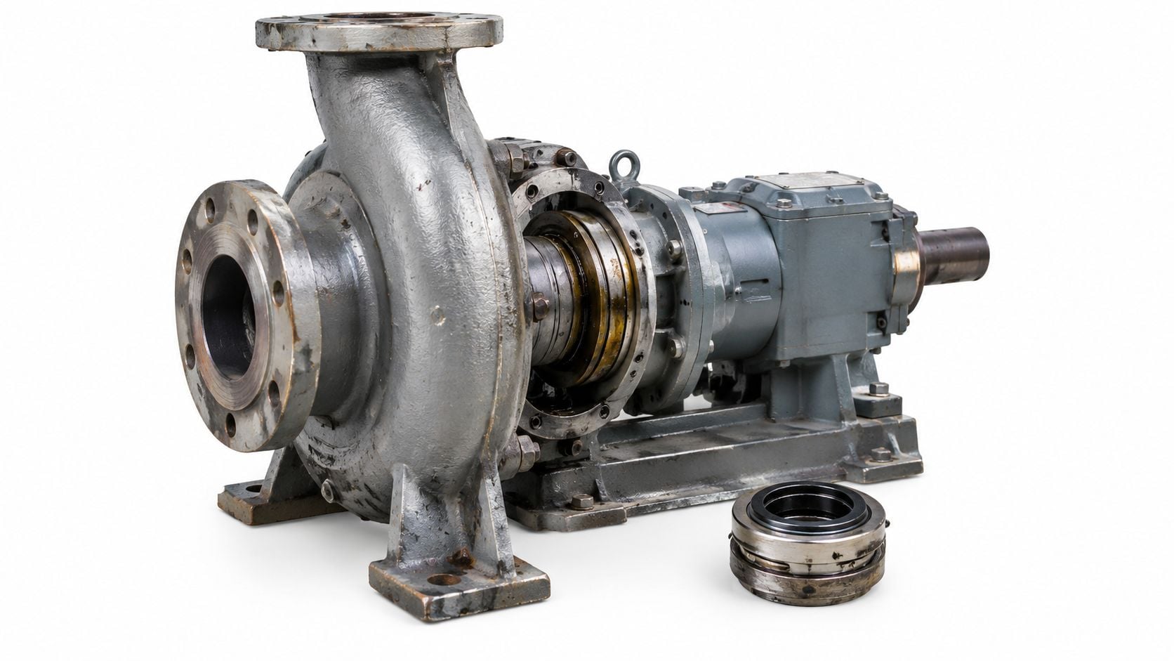
The third event triggered a structured investigation. An ultrasonic survey detected vapor at the throat. Inspection of the flush line found a partially blocked orifice. Process-data review then correlated failures with batch startups, when suction specific speed dropped and the pump experienced a transient hydraulic condition.
The RCA team separated the clues:
- Symptom: Glazed rotating face with a localized hot spot.
- Mechanism: Inadequate flush during transient operation, causing loss of cooling and unstable face lubrication.
- Underlying cause: An oversized minimum-flow orifice and a missing startup bypass allowed the seal environment to deteriorate during batch initiation.
The corrective action wasn't a more expensive replacement seal. The team corrected the flush restriction, added startup protection, verified the hydraulic sequence, and established a teardown record for future events. Chemical processors managing comparable duties can also review centrifugal pumps for chemical processing through the lens of transient conditions, not only steady-state nameplate values.
Short-Term Repairs and Permanent Fixes
A repair can restore service without improving reliability. During a turnaround or unplanned outage, the crew may lap or reface seal faces, replace O-rings, clean the chamber, flush deposits with a compatible solvent, correct gland loading, and realign the pump with a laser system. Those actions matter, but they only work when the original failure mechanism has been removed.
For packing, gland torque should be adjusted to the required controlled leakage and monitored for temperature and shaft wear. For a mechanical seal, the crew should verify the set dimension, face cleanliness, gland squareness, shaft or sleeve condition, flush connection, and alignment before release. A seal that looks correct on the bench can fail quickly if the support system remains blocked or the pump starts without liquid.
Selecting an engineering change
Permanent fixes move upward from component replacement to design control:
- Hydraulic instability: Correct minimum-flow control, startup sequencing, suction conditions, and operation near the pump's BEP.
- Flush starvation: Replace an unreliable arrangement with a properly sized Plan 32 pumped-circulation loop, or another arrangement suited to the service.
- Abrasive contamination: Add a cyclone separator or magnetic filter where compatible, and select face materials that tolerate the actual solids.
- Chemical attack: Upgrade metallurgy, potentially including silicon carbide for corrosive chemical duties, and verify elastomer compatibility with process and cleaning fluids.
- Thermal overload: Improve cooling, reduce seal-chamber heat generation, or use tandem or double-pressurized seals when the containment and process risk justify the added complexity.
- Excessive stuffing-box velocity: Add a throat bushing where the design requires reduced circulation or improved control of the seal chamber environment.
- Packing-related damage: Consider a balanced mechanical seal when water loss, shaft wear, emissions, or maintenance exposure make controlled leakage the better operating choice.
A tandem or double-pressurized arrangement can improve containment and control, but it adds barrier-fluid instrumentation, maintenance requirements, and failure modes. A higher-grade face material may resist abrasion, yet it won't correct dry running. Reliability decisions should weigh the service, hazard, criticality, and support-system capability instead of upgrading components by habit.
| Root Cause Family | Short-Term Repair | Permanent Fix / Design Change |
|---|---|---|
| Installation error | Replace damaged secondary seals and correct set dimension | Standardize installation, training, torque control, and verification |
| Misalignment or shaft movement | Realign and measure runout | Repair bearings, sleeve, coupling, pipe strain, or shaft-support design |
| Dry running | Replace faces and restore liquid supply | Add low-level, flow, or startup interlocks |
| Flush starvation | Clean line and restore temporary flow | Resize or redesign flush circuit with flow and pressure monitoring |
| Thermal overload | Replace damaged faces and elastomers | Improve cooling, circulation, seal selection, or dual-seal arrangement |
| Contamination | Clean chamber and replace damaged components | Add separation, filtration, compatible flush, or better face materials |
| System design | Return pump to a stable temporary duty | Correct impeller, minimum flow, parallel operation, and thermal relief |
If the failure recurs within the same mean time, the previous fix didn't address the cause. The maintenance record should then escalate the asset from repair work to engineering review.
Monitoring, RCM, and Closing the Reliability Loop
A seal reliability program starts with failure-mode logic, not a calendar replacement interval. Reliability-centered maintenance, or RCM, compares the consequence and detectability of each failure mode with the cost and practicality of the maintenance task. A critical chemical pump may justify continuous flush monitoring and periodic vibration routes. A low-consequence utility pump may be managed through basic inspection or run-to-failure.
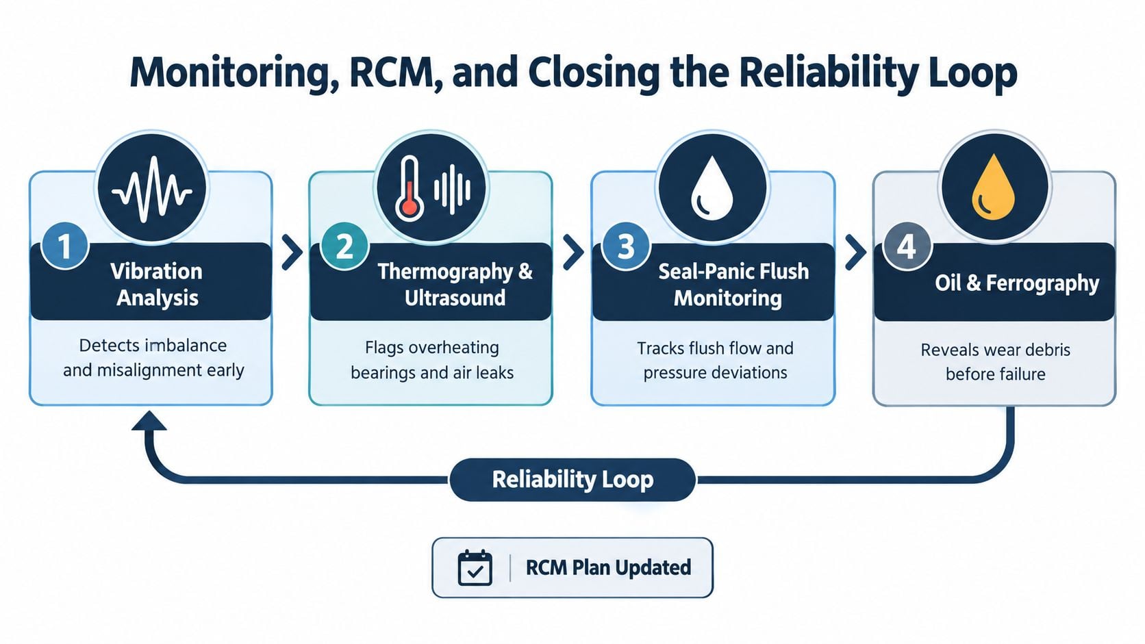
The monitoring stack should reflect the physics already identified:
- Vibration analysis identifies imbalance, misalignment, looseness, bearing deterioration, and hydraulic instability before those conditions destabilize the seal.
- Thermography and ultrasound reveal abnormal heat, cavitation, vapor formation, and leakage behavior.
- Seal-panic flush monitoring tracks flush flow, pressure, temperature, and deviations from the established operating state.
- Oil analysis and ferrography identify wear debris from bearings, sleeves, and other rotating components that can transmit instability into the seal.
Turning evidence into maintenance decisions
The FMEA, or failure modes and effects analysis, identifies how the pump can fail and what evidence should be collected. RCA then tests the actual failure against those assumptions. A cause-code taxonomy such as ISO 14224 can help reliability teams classify equipment and failure data consistently across sites, provided the local codes capture the mechanism rather than only the failed component.
The closed-loop workflow should be explicit:
- Preserve the failed seal and record operating conditions.
- Match physical damage to a failure mechanism.
- Verify the mechanism with dimensional checks and condition data.
- Update PM routes, alarm thresholds, startup procedures, and inspection points.
- Raise an engineering change request when the operating envelope or design is responsible.
- Review repeat events and confirm that the intervention changed the failure pattern.
A condition-based task should trigger from evidence such as rising vibration, abnormal flush temperature, declining flow, or increasing leakage trend. Proactive replacement may be justified when failure consequences are severe and degradation is detectable. Calendar replacement alone is weak when the actual failure is caused by a batch startup, a closed valve, or a blocked flush line.
Forge Reliability delivers condition monitoring and reliability consulting that can combine vibration analysis, oil analysis, thermography, ultrasound, FMEA, RCM, and root cause methods around rotating equipment. The recurring leak should be treated as a systems problem, with the seal, pump hydraulics, shaft train, support system, operating procedure, and data record reviewed together.
A free reliability assessment from Forge Reliability can examine recurring pump seal failures, flush-system performance, vibration evidence, operating conditions, and maintenance history. The assessment gives reliability and operations teams a practical path from repeated seal replacement to verified corrective action.