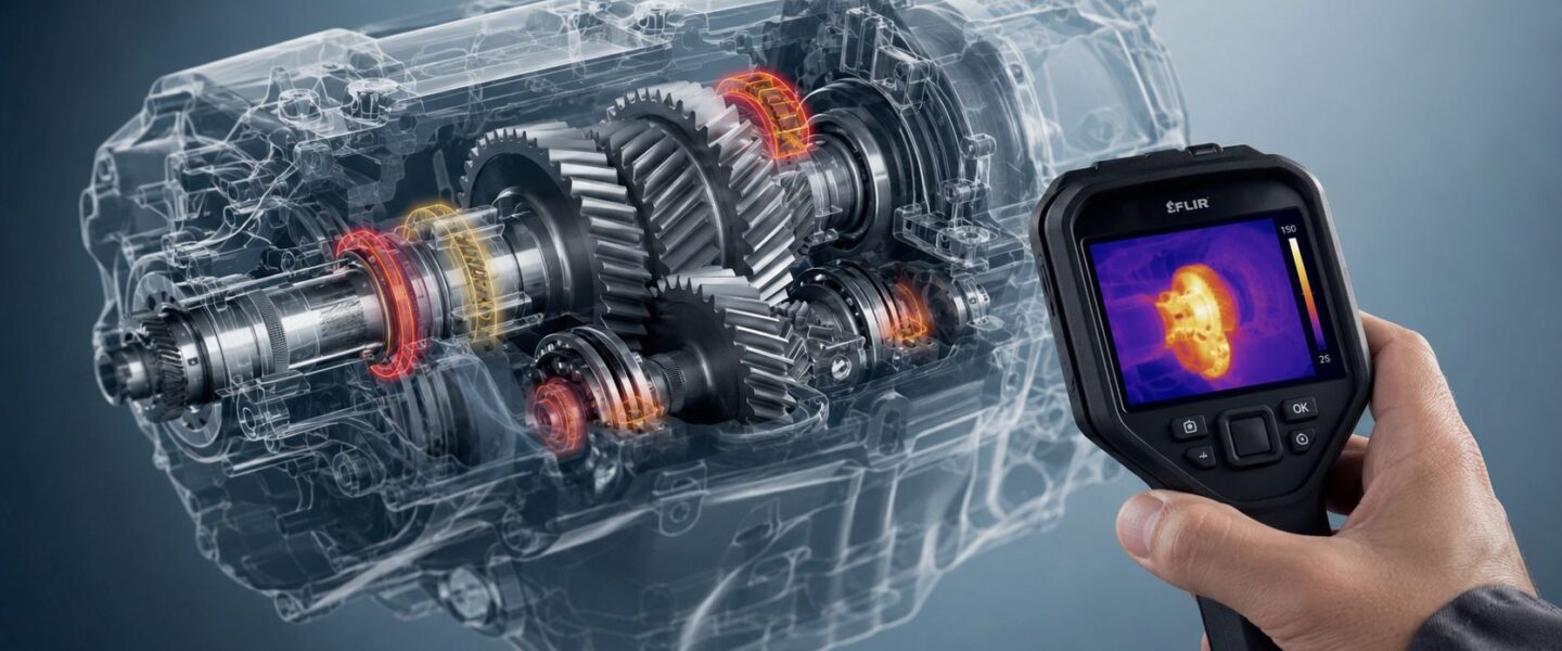
Bearings account for about 70% of gearbox failures, while gears account for about 26%, according to a large NREL dataset built from 257 damaged records. The most common failure mode was axial cracking in high-speed-shaft or intermediate-speed-shaft bearings, not a broken gear tooth. That finding changes the first troubleshooting question from “Which gear failed?” to “Where did the distress begin?” NREL gearbox reliability data
A gearbox rarely fails at the location where the first defect started. A bearing fault can create gear-mesh sidebands. A lubrication problem can produce particles that later damage bearings and gear flanks. A misaligned coupling can shift load into a bearing edge until the teardown appears to show a component failure rather than an installation failure.
The practical challenge is choosing the right evidence at the right time. Oil analysis can reveal slow surface distress before a route-based vibration program sees a decisive spectral change. Vibration can override an apparently acceptable oil sample when a bearing is generating low-energy impacts with little debris. Under variable load, temperature, vibration, and oil data may each describe only part of the same developing failure.
Table of Contents
- Why Gearbox Failures Start Where You Least Expect
- The Six Core Gearbox Failure Modes Explained
- Diagnostic Signatures Across Condition Monitoring Methods
- Root Causes Behind Operating and Installation Failures
- Mixed Mode Damage Under Variable Load Conditions
- A Practical Diagnostic Workflow for Gearbox Troubleshooting
- Integrating FMEA and RCM Into Your Gearbox Strategy
- Building a Monitoring Program That Prevents Repeat Failures
Why Gearbox Failures Start Where You Least Expect
A large NREL dataset found that bearings represented about 70% of gearbox failures, compared with about 26% for gears and 4% for other components. The records included 180 bearing-related events, 68 gear-related events, and 9 events in other parts. That distribution supports a practical first check: inspect bearing condition before assuming that a prominent gear-mesh peak proves tooth damage. NREL damage records and component distribution
Damage was concentrated in the gearbox's parallel section, and axial cracking in the high-speed-shaft or intermediate-speed-shaft bearing was the most common individual failure mode. If lubrication, contamination, or loading problems persist, axial cracks can develop into larger spalls or a fracture.
Why teardown evidence misleads
A failing planet or parallel-section bearing can excite gear-mesh frequencies and their sidebands. In a fast Fourier transform, or FFT, spectrum, the visible peak may look like a gear defect even though the bearing produced the original impulse. Analysts need to examine modulation around the mesh frequency, bearing defect frequencies, shaft orders, and the time waveform before assigning the fault to a gear.
Oil debris sensors provide different evidence. They respond to wear particles, but those particles may reflect secondary damage or appear only after bearing distress has advanced. An apparently acceptable particle count does not clear a bearing when vibration shows repetitive low-energy impacts. Conversely, particles with little corresponding vibration may indicate surface distress that deserves sampling, inspection, or a repeat oil test before an immediate teardown.
Variable load makes the decision harder. Load changes can alter vibration amplitude, temperature, and particle generation independently, so a single threshold may miss the transition from an initiating fault to mixed component damage. Use the trend, operating condition, and failure mechanism together.
Practical rule: Failure origin and observed damage are rarely identical. The first repair decision should explain both the damaged component and the mechanism that loaded it.
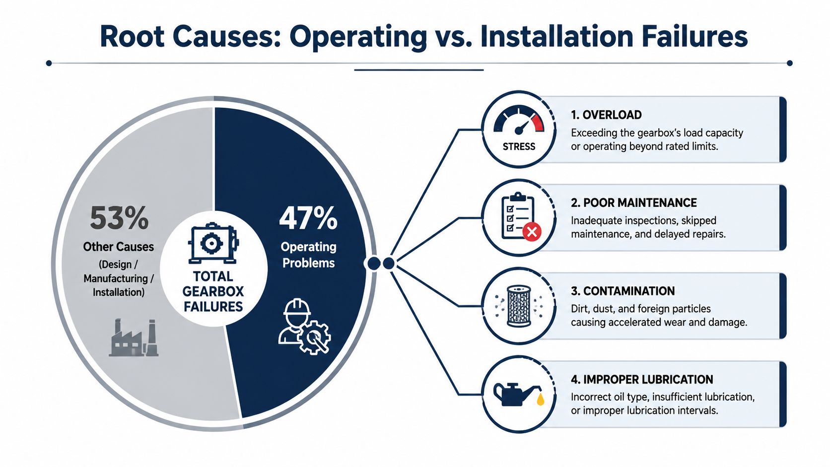
Misalignment and lubrication breakdown can precede visible mechanical damage for long operating periods. Periodic route inspections may miss the change between sampling intervals, especially when load and speed vary. Historical failure literature attributes about 19% of gear-system failures to misalignment, while another cited distribution assigns 47% to operating problems, 36% to vendor problems, and 17% to extraneous influences. Historical gearbox failure literature
| Failure Origin | Observed Damage at Teardown | Percentage of Cases | Typical Misdiagnosis |
|---|---|---|---|
| Bearing distress | Spalling, axial cracking, or secondary gear damage | About 70% | Gear mesh fault |
| Gear distress | Pitting, scuffing, wear, or tooth damage | About 26% | Treating lubrication or alignment as unrelated |
| Other component damage | Shaft, seal, or auxiliary-part damage | About 4% | Replacing the visible part without checking loading |
| Operating or process contribution | Mixed component damage | 47% operating problems in cited historical distribution | Blaming metallurgy alone |
The six core gearbox failure modes are bearing damage, pitting, scuffing, misalignment-induced loading, lubrication failure, and contamination ingress. Each produces a different combination of vibration, oil, heat, and visual evidence. The dependable diagnosis comes from matching the monitoring method to the physical mechanism, then checking whether the proposed repair removes the initiating cause.
The Six Core Gearbox Failure Modes Explained
Gear failure mechanisms are commonly organized into surface disturbances, scuffing, deformations, surface fatigue, fissures or cracks, and tooth breakage. That taxonomy helps technicians connect an inspection finding to a corrective action instead of treating every polished, scored, or damaged tooth as the same problem. Gear failure mechanisms in wind-turbine gearboxes
Bearing wear and spalling
Bearing fatigue begins beneath the rolling contact, where repeated shear stress eventually exceeds the material's endurance. A technician may find grey staining, flaking, axial cracks, or spalls on the raceway. High-frequency enveloping, which extracts repetitive impact energy from a vibration signal, is usually the earliest useful method for an incipient rolling-element defect.
Bearing damage classification should follow the terminology in ISO 15243, especially when distinguishing fatigue, lubrication-related distress, contamination, and deformation. A bearing fault can also produce modulation around gear-mesh frequencies, so the analyst should compare bearing defect frequencies, shaft orders, axial acceleration, and load conditions rather than relying on a single peak. Teams troubleshooting recurring bearing failures can also use this bearing failure reference to structure the inspection sequence.
Gear tooth pitting
Micropitting appears as fine grey frosting or staining on a tooth flank. It develops when the lubricant film is too thin for the surface pressure and sliding conditions, allowing small fatigue cracks and material removal. Macropitting produces larger craters and can grow into spalling when repeated contact stress extends subsurface cracks.
Ferrography, which separates and examines ferrous wear particles, can identify the transition from mild surface distress to more aggressive fatigue debris. Vibration sidebands around the gear-mesh frequency become more useful as the damaged area grows. Early micropitting may support continued operation with corrected lubrication and tightened monitoring, while active macropitting, dense sidebands, or rapid amplitude growth can justify a planned or immediate intervention.
Scuffing and adhesive wear
Scuffing occurs when the lubricating film collapses and opposing surfaces weld or tear locally. The inspection signature is directional scoring, smeared metal, and discolored tooth flanks. Thermography can identify abnormal heat, but temperature often lags behind the active contact damage, so oil condition and high-frequency vibration should be reviewed first.
Misalignment-induced loading
Misalignment shifts the load zone across the tooth face and can create edge loading on bearings. The technician may see uneven tooth contact, localized polishing, recurring seal leakage, or heat concentrated near one housing location. Phase analysis, shaft-orbit analysis, and precision alignment checks are more useful than overall vibration alone because they help separate angular or offset misalignment from looseness and balance problems.
Lubrication failure and contamination
Lubrication failure includes incorrect viscosity, additive depletion, oxidation, insufficient film thickness, and excessive churning. Contamination adds water, dirt, or metallic debris that can abrade surfaces and initiate fatigue. Oil analysis detects these mechanisms through viscosity, particle morphology, elemental content, and water trends, while inspection may reveal axial scratches, rust staining, or abrasive polishing.
Reliability teams often improve results by borrowing disciplined review habits from other operational systems. A practical resource on continuous improvement methodologies for IT can help structure recurring gearbox investigations around documented causes, corrective actions, and verification rather than isolated repairs.
Diagnostic Signatures Across Condition Monitoring Methods
No single sensor captures every gearbox failure at the same stage. Vibration analysis responds well to repetitive impacts, modulation, and structural changes. Oil analysis identifies wear debris, contamination, and lubricant degradation. Thermography usually shows friction or load-related heat after the mechanism has developed, while motor-current signature analysis, or MCSA, can reveal changes in the driven electrical system without reliably separating mechanical from electrical causes.
| Failure Mode | 1st Detection Method | 2nd Detection Method | Key Threshold / Standard |
|---|---|---|---|
| Bearing fatigue or axial cracking | High-frequency enveloping and axial acceleration | Oil ferrography and particle trends | Alarm escalation should follow site baseline and confirmed defect-frequency growth |
| Gear pitting | Vibration sideband analysis | Ferrography and visual inspection | A published guide cites a 20% GMF amplitude increase above baseline vibration diagnosis guide |
| Advanced gear spalling | Dense sideband families | Immediate inspection or teardown | The guide cites sideband amplitude above 60% of GMF amplitude and a 1-to-4-week remaining-life estimate for advanced spalling |
| Scuffing | Oil condition and temperature trend | Vibration high-frequency energy | Escalate when heat and wear evidence rise together |
| Contamination | Particle counting and elemental spectroscopy | Vibration and filter inspection | Use the site's approved cleanliness limits and contamination source checks |
| Misalignment | Phase analysis and precision alignment | Vibration order analysis and thermal imaging | Escalate when phase, temperature, and contact-pattern evidence agree |
The guide also identifies a 15% increase in the sideband-to-GMF ratio as a warning threshold, with an alarm condition when sideband amplitude exceeds 50% of GMF amplitude, indicating moderate to advanced pitting. Treat these values as escalation criteria, not replacements for a verified machine baseline. Variable torque can push a gearbox across a threshold during a transient, so analysts should confirm the pattern across comparable load states.
When vibration overrides oil: A bearing cage defect may produce low-energy impacts with little debris. A clean-looking sample does not cancel a repeatable enveloped impact pattern.
Oil analysis can lead the diagnosis in other cases. Slow-speed gear pitting may generate wear particles while remaining difficult to resolve in vibration below 10 Hz shaft frequencies. Ferrography, rising particle concentration, and a concurrent viscosity or contamination change can provide the earlier warning.
The decision depends on the damage mechanism and operating state. Use oil results first when debris or lubricant change is the clearest evidence. Let repeatable, load-matched vibration patterns override a clean sample when impact energy points to an active bearing or gear defect.
Overall velocity remains useful for screening, but a stable global value can conceal localized bearing impacts. Cepstrum analysis examines periodic spacing between spectral components and can expose repeated modulation patterns. Thermography can confirm developing friction or load problems, although it generally trails active scuffing.
A structured industrial gearbox condition-monitoring program should combine at least two independent evidence streams before a persistent abnormality is dismissed. Mixed-mode damage under variable loads makes single-sensor alarm logic unreliable, especially when oil, vibration, and temperature trends do not rise together.
Root Causes Behind Operating and Installation Failures
A gearbox can pass factory testing yet fail early in service because plant conditions change the load, lubrication, and alignment it experiences. Historical distributions assign roughly half of failures to operating problems, with vendor issues and external influences accounting for the remainder. Misalignment also appears as a recurring contributor, so installation and operating audits belong beside component inspection.
Operating conditions that accelerate damage
Sustained overload raises tooth contact stress and bearing load. Start-stop cycling and torque reversals create transient forces that a nameplate rating may not represent. Thermal shock changes lubricant viscosity and clearances, while weak lubrication control reduces the film separating loaded surfaces.
The damage mechanism follows the combination of conditions. High sliding with a thin film favors micropitting or scuffing. Repeated overload promotes macropitting, tooth cracking, or bearing fatigue. Water and solid contamination add corrosion and abrasive wear, creating sites for contact fatigue.
Historical failure distributions assign roughly half of failures to operating problems. That makes the operating envelope the first audit point, especially when vibration and oil results appear inconsistent.
Installation errors that remain in service
Soft foot, pipe strain, uneven mounting surfaces, coupling offset, and incorrect thermal-growth assumptions can apply static loads before production torque reaches the gearbox. These forces shift bearing load zones and concentrate stress along tooth edges. An unloaded commissioning alignment may look acceptable while the operating contact pattern remains poor.
A practical audit should verify:
- Operating envelope: Compare actual torque, speed, starts, stops, reversals, ambient temperature, and process disturbances with the design duty.
- Lubricant control: Confirm specified viscosity, additive condition, storage practice, breathers, seals, filtration, and sampling location.
- Alignment quality: Measure soft foot, coupling alignment, shaft position, pipe strain, and thermal growth under realistic conditions.
- Load path: Inspect belts, chains, couplings, overhung loads, foundations, and mounting bolts for forces that shift the housing or shaft centerline.
- Failure evidence: Preserve oil, filters, magnetic plugs, photographs, contact patterns, and damaged components before cleaning.
A maintenance team investigating shaft misalignment should connect the alignment result with the observed damage. Correcting alignment without reviewing lubrication and load history may remove one contributor while leaving the initiating process condition in place. Preserve the evidence first, then correct the condition that can produce the same damage again.
Mixed Mode Damage Under Variable Load Conditions
Wind-turbine gearboxes make mixed-mode damage easy to see because torque and speed vary continuously. Wind gusts, grid transients, and changing drivetrain load can excite bearing fatigue, gear surface distress, and cage instability at the same time. In a standard FFT spectrum, overlapping responses can obscure the progression of an individual defect.
A representative diagnostic sequence begins with fine surface distress on a high-speed pinion under low-load, high-speed operation. As gust loading increases contact stress and reduces the margin provided by the elastohydrodynamic film, micropitting can progress toward macropitting. A bearing may develop axial cracking during the same operating period, producing vibration modulation that analysts attribute to the gear mesh.
The key decision is not whether one sensor crossed an alarm. It is whether the combined evidence shows a mechanism progressing toward loss of containment or structural failure.
| Damage Stage | Load Condition | Primary Mechanism | Earliest Detection Method | Typical Lead Time |
|---|---|---|---|---|
| Lubricant degradation | Variable load and temperature | Film weakness, oxidation, or contamination | Oil analysis | Qualitative early warning before visible distress |
| Micropitting | Low-load, high-speed contact | Surface fatigue under limited film thickness | Ferrography and targeted vibration | Earlier than obvious tooth damage |
| Bearing distress | Repeated variable loading | Subsurface fatigue or axial cracking | Envelope vibration and axial acceleration | Before major spalling when the signature is repeatable |
| Macropitting or spalling | Higher transient contact load | Crack growth and surface material loss | Sideband analysis plus inspection | Rapid escalation once damage is established |
| Mixed structural damage | Continued operation with unresolved causes | Interacting bearing, gear, and lubrication faults | Hybrid monitoring and teardown evidence | Lead time depends on progression and criticality |
A single-sensor program can produce false negatives. Oil debris may appear before vibration trends become decisive, while vibration may become urgent before oil debris reaches a meaningful concentration. Temperature trending adds context, but it can remain stable while subsurface fatigue advances. Hybrid monitoring combines oil analysis, vibration enveloping, and temperature trends so the team can distinguish an isolated transient from a developing failure mechanism.
The practical response is to tighten sampling and correlate every signal with torque, speed, and operating state. If the evidence indicates advanced spalling, continued operation should be justified by engineering review, not by a stable overall velocity value.
A Practical Diagnostic Workflow for Gearbox Troubleshooting
A reliable troubleshooting process begins with the first abnormal indication and protects evidence before corrective work changes the failure scene. The decision tree should also match each sensor to the damage mechanism.
Triage the alert. Compare oil wear-metal trends with vibration spectra, envelope data, axial acceleration, temperature, speed, and load. Repeatable bearing-frequency evidence with little debris supports vibration-led escalation. Rising fatigue debris with weak vibration supports an oil-first investigation, particularly in slow-speed gear distress. When signals disagree, keep both hypotheses open rather than averaging them into one alarm.
Check the operating context. Separate steady-state data from starts, stops, torque reversals, and load changes. A transient peak is not automatically a progressive trend. Repeated peaks under the same operating condition warrant targeted investigation, especially when variable load can hide intermittent contact or looseness.
Perform a focused inspection. Where safe, use a strobe light to inspect accessible gear surfaces, thermal imaging to locate hot spots, and phase analysis to evaluate alignment-related behavior. Review breathers, seals, filters, magnetic plugs, oil level, and recent maintenance records. These checks connect the instrument response to a physical condition.
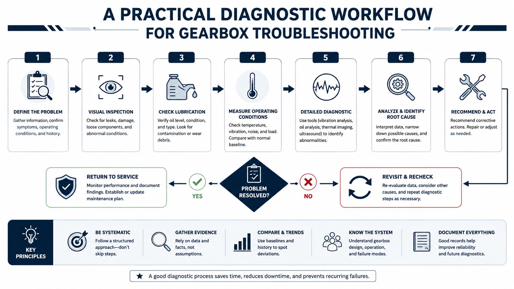
Apply escalation gates. Use the published threshold table above for vibration escalation. Do not treat an overall velocity value as reassuring when gear-mesh or sideband evidence is worsening. Thresholds support the decision, but trend direction, operating state, and corroborating evidence determine whether the machine remains in service.
Choose monitoring or teardown. Tighten sampling when evidence remains limited, the trend is stable, and production criticality permits controlled operation. Order a teardown when defect signatures grow rapidly, multiple methods agree, heat rises with wear evidence, or failure consequences make continued operation unacceptable. Mixed-mode damage often requires teardown because no single sensor can establish the full mechanism.
Preserve evidence. Photograph gear flanks, bearing raceways, seals, filters, and magnetic plugs before cleaning. Retain oil and debris samples, document contact patterns, and record the operating history preceding the damage. Preserve raw waveforms and spectra when vibration triggered the inspection.
Confirm the root cause. Replacing a component does not complete the investigation. The final report should connect the failure mode to alignment, load, lubrication, contamination, installation, or process conditions, then assign a verification task that proves the corrective action worked under representative operating conditions.
Integrating FMEA and RCM Into Your Gearbox Strategy
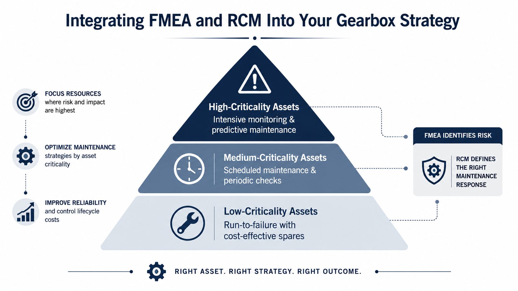
Treating every gearbox identically wastes monitoring effort on low-consequence assets and leaves critical units without enough evidence. Failure Modes and Effects Analysis, or FMEA, ranks credible failure mechanisms by their effect and detectability. Reliability-Centered Maintenance, or RCM, then tests whether a condition-based task, scheduled restoration, scheduled replacement, or run-to-failure approach fits each mechanism.
A high-criticality wind-turbine main gearbox may justify continuous vibration surveillance for a high-speed bearing because an undetected fault can affect production and repair planning. A low-criticality auxiliary drive may be better served by periodic oil analysis, visual checks, and stocked spares. The correct interval depends on consequence, failure development, access, operating variability, and the quality of available signals.
FMEA should map each gearbox failure mode to its earliest credible indicator:
- Bearing fatigue: Envelope vibration, axial acceleration, and oil debris review.
- Gear pitting: Gear-mesh sidebands, ferrography, and tooth inspection.
- Lubrication failure: Viscosity, contamination, temperature, and filtration checks.
- Misalignment: Phase analysis, contact pattern, coupling alignment, and thermal evidence.
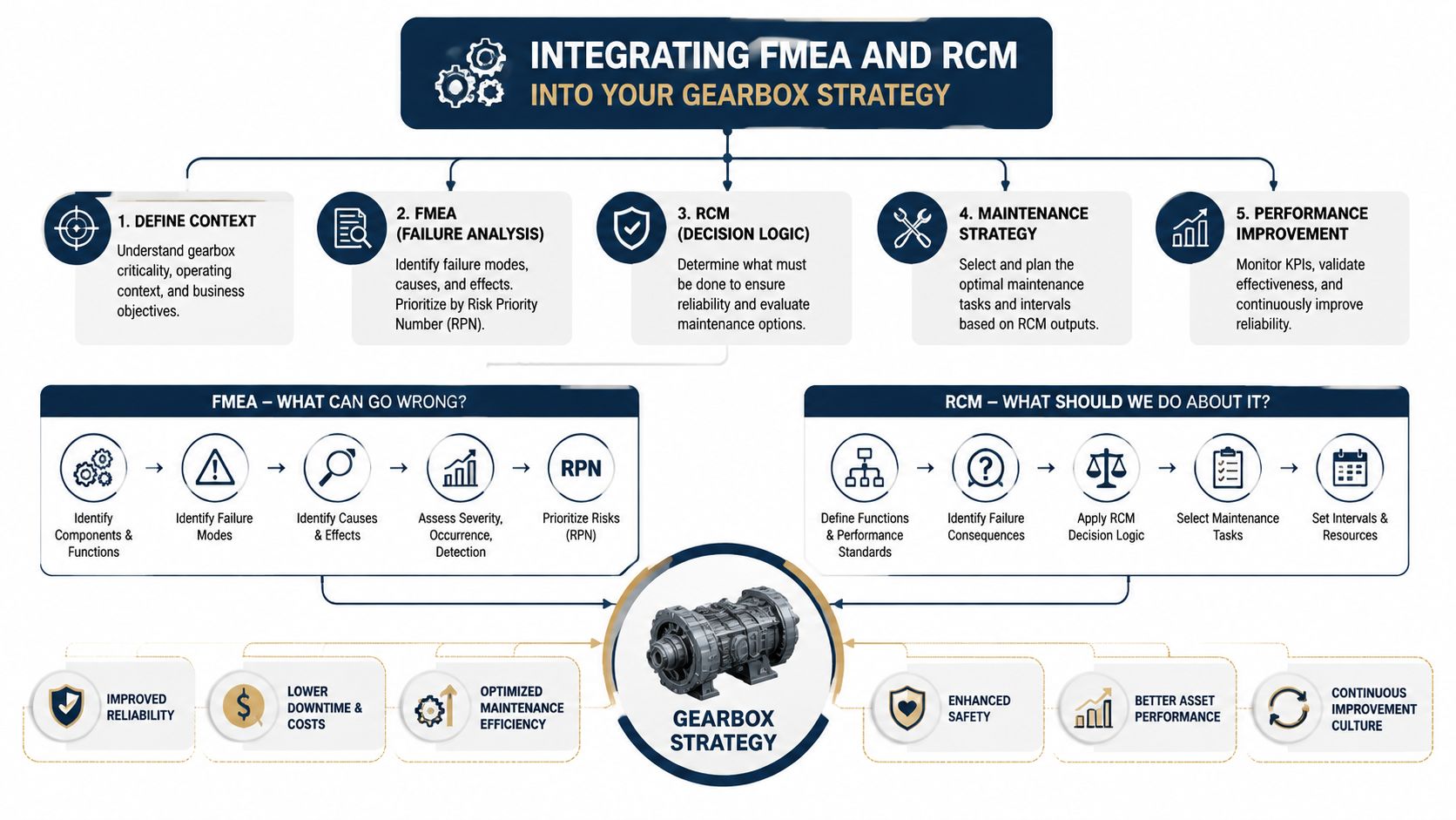
RCM decision logic also prevents a common mistake, replacing components on a calendar when the failure mechanism is random or condition-dependent. The framework described in reliability-centered maintenance practice helps teams connect criticality ranking to task selection instead of assigning the same inspection plan to every asset.
Building a Monitoring Program That Prevents Repeat Failures
More sensors don't automatically create better reliability. Instrumentation only helps when the team knows which gearbox failure modes matter, what each signal can detect, and which decision follows a confirmed change.
A practical program starts with the failure history. Oil analysis should target lubricant and debris mechanisms. Vibration should focus on bearing impacts, gear-mesh modulation, and changes under comparable load. Thermography should confirm thermal consequences, while alignment checks address a root cause that sensors may only describe indirectly.
The maintenance plan should define sample quality, baseline conditions, escalation ownership, and evidence preservation before the next alarm occurs. Guidance on industrial gearbox maintenance, inspection, and lubrication can help teams align those activities into one repeatable process.
Forge Reliability provides predictive maintenance, condition monitoring, failure analysis, FMEA, RCM, and asset-management support for industrial gearbox programs. Its engineers can review failure history, compare oil and vibration evidence, identify monitoring gaps, and develop a phased plan around asset criticality.
For a free reliability assessment, visit Forge Reliability to review recurring gearbox failures, monitoring blind spots, and root-cause investigation practices with reliability specialists. The assessment can help identify whether oil analysis, vibration, alignment verification, or a focused teardown should lead the next maintenance decision.