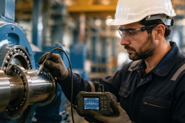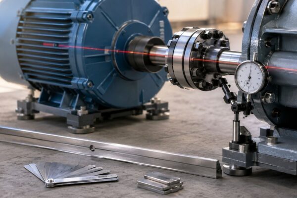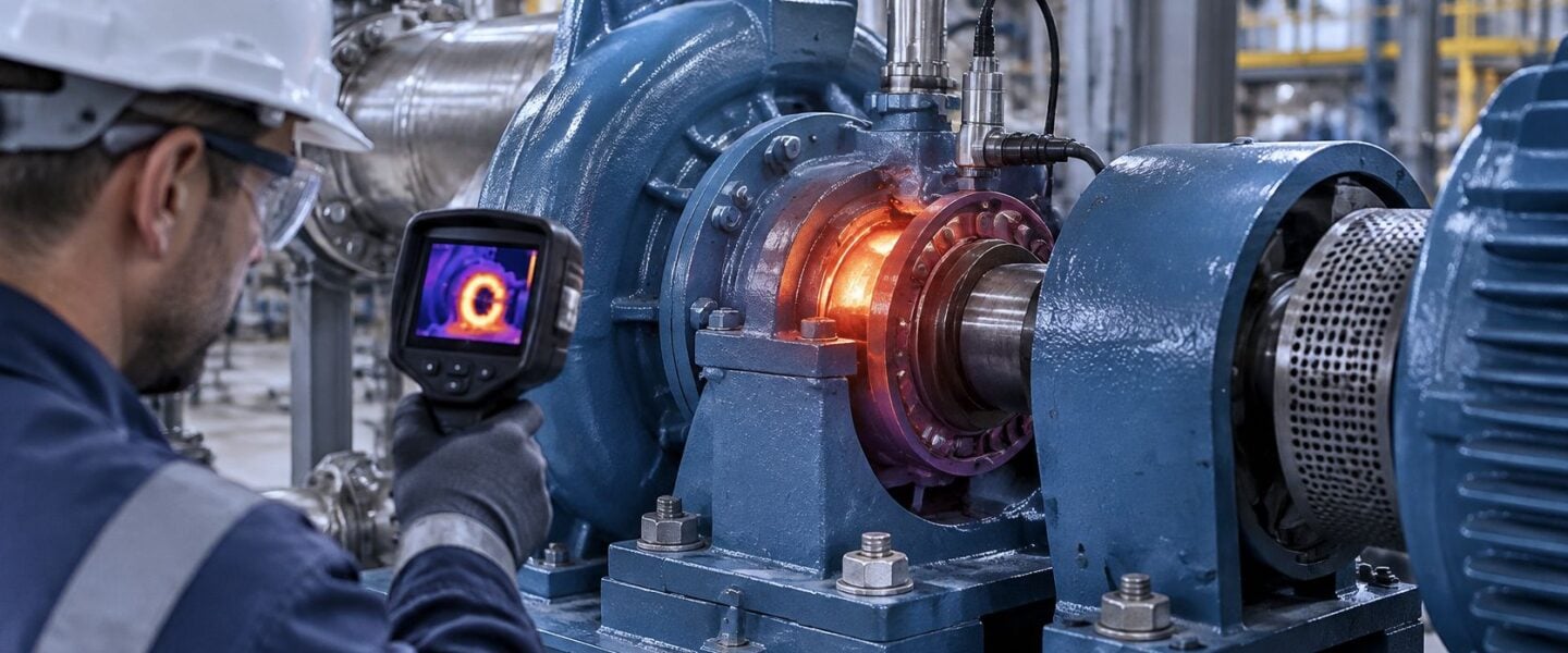
A steel-mill boiler-feed pump is running at steady load and speed, but its drive-end bearing housing reads 92°C while the opposite end reads 68°C. The shift is tempted to add grease and keep the pump online. That may be the wrong move: one housing alarm is a symptom, not a diagnosis, and the right limit belongs to the specific bearing, lubricant, and operating baseline.
The practical question isn't whether a bearing is hot. It's whether the temperature is above that bearing's material and lubricant limits, rising against its normal baseline, or pointing to a failure mechanism that needs action now.
Table of Contents
- Bearing Temperature Limits That Matter
- How to Confirm a High Bearing Temperature
- Diagnostics That Separate One Hot Bearing From Another
- Causes of High Bearing Temperature
- How to Correct a Hot Bearing and Prove It
- Monitoring Tips That Catch the Next Rise
- Book a Free Reliability Assessment
Bearing Temperature Limits That Matter
For the boiler-feed pump, 92°C at one housing is a trigger for investigation. Which trip value applies depends on the component: temperature limits sit separately on the rings, rolling elements, cage, seals, and lubricant, and each can carry a different thermal ceiling. The limits below are reference points for specific cases. The alarm that matters comes from the bearing's own catalog, baseline, and trend.
| Case | Reference temperature | What it means | Decision |
|---|---|---|---|
| Oil-bath rolling bearing, ISO 15312 reference | Fixed ambient plus a defined temperature rise | Standardized mean-temperature baseline | Rebaseline when ambient or duty changes; don't trip on this value alone |
| Standard rolling bearing, dimensional stability | Catalog dimensional-stability limit | Hardness and catalog-life assumptions stop holding above it | Check the bearing's stabilization grade before accepting hotter operation |
| Heat-stabilized rolling bearing | Higher ceiling set by heat-treatment grade | The limit belongs to the specified stabilization grade | Read the bearing marking and catalog; a site-wide alarm can't capture it |
| Standard grease at the hottest ring | Ceiling set by the grease specification | Grease life falls with exposure time at temperature | Check the lubricant and film before adding grease |
| Precision machine-tool spindle, outer ring | OEM stop limit during run-in | Protects positional accuracy on high-speed equipment | Run a limit switch; repeat run-in until the temperature holds, then keep running briefly to confirm |
| Published ball-bearing life test | 85°C and 9 m/s² vibration (Mendeley Data ball-bearing life-test dataset) | Laboratory test-termination thresholds | Keep lab termination limits out of plant setpoints |
| Steam-turbine journal bearing | Rising metal temperature with a growing shaft orbit | Indicates babbitt wear | Trend shaft orbit and metal temperature together |
The Schaeffler bearing-data guidance ties the thermal ceiling to the bearing's stabilization grade, cage, seals, and lubricant. Standard rolling bearings are dimensionally stable up to 120°C (248°F), and specially heat-treated grades carry ratings of 150, 200, 250, 300, or 350°C by grade. Past the applicable temperature, hardness drops and the rated-life calculation loses its assumptions, even if the bearing still turns.
The ISO 15312 figure plays a different role: it is a baseline for comparison. ISO 15312:2018 defines thermal speed rating for oil-bath-lubricated rolling bearings from reference conditions built on a fixed ambient temperature plus a defined temperature rise. A sustained reading well above that baseline points to excess friction, over-lubrication, incorrect viscosity, misalignment, excessive preload, or weak cooling while the material limit is still far off.
Equipment-specific limits travel with the machine. A precision spindle's run-in stop limit protects thermal accuracy on that equipment and its procedure; it does not transfer to a boiler-feed pump. An accelerated life test that ends at fixed temperature and vibration thresholds is a laboratory control, so its termination values stay in the lab report.
For the pump, write down four figures before changing anything: the bearing's stabilization grade, the lubricant's temperature limit, the OEM housing alarm, and the normal baseline at matching load, speed, and ambient conditions. Add a fifth observation: how fast the temperature climbed. Rate of rise separates a lubrication problem that developed over shifts from a sudden mechanical change, and until the mechanism is proven, added grease is a suspect. That comparison gives the team a real threshold instead of a borrowed one.
How to Confirm a High Bearing Temperature
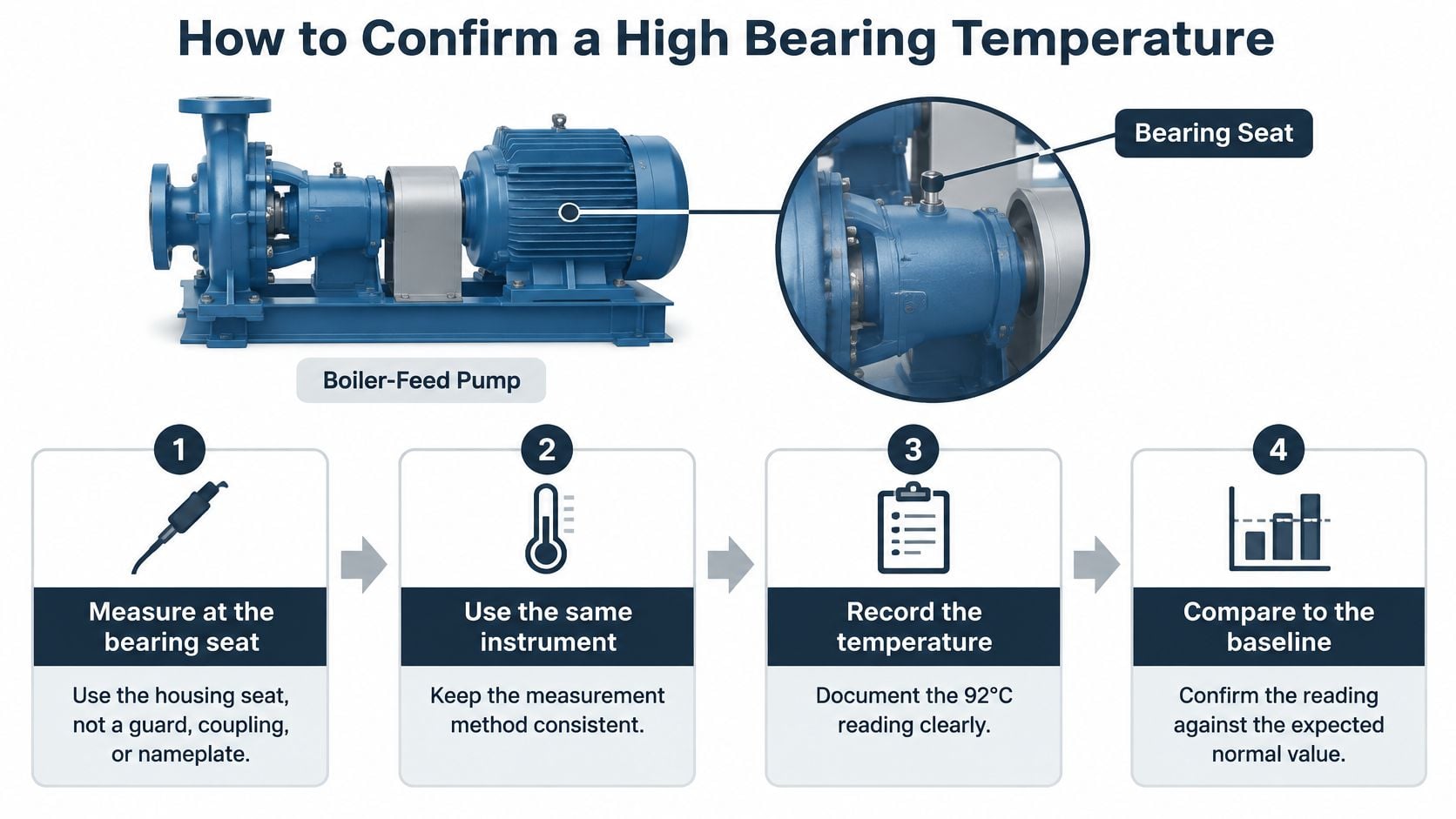
Before naming a cause for the pump's 92°C reading, prove that the reading is repeatable and comparable. A sudden rise under unchanged operating conditions can signal developing damage, but an absolute temperature alone can mislead: process heat, ambient conditions, speed, and cooling all affect the machine's heat balance.
- Measure at the bearing seat. Take the reading on the housing at the bearing seat, not on a guard, coupling, or nameplate, because those locations don't represent the same thermal point.
- Check the instrument reading safely. Where access allows, verify an infrared reading with a contact probe; reflective or freshly painted surfaces can produce misleading infrared readings.
- Record the operating conditions. Note temperature, load, speed, and ambient conditions, then repeat under the same conditions so the readings can be compared.
- Compare like with like. Check the drive end against the opposite end and a sister pump at similar duty; a temperature difference only means something when measurement locations and conditions are comparable.
- Trend thermal and vibration data together. Record vibration velocity and enveloped acceleration, which can help distinguish a sudden change on steady duty from a short-lived rise after start-up or greasing.
- Inspect lubrication after confirming the reading. Check grease condition and level, purge path, oil viscosity, and contamination; adding grease before confirming the measurement can hide the original signal or worsen churning.
- Check the mechanical setup. Verify coupling alignment, shaft runout, fits, axial float, and preload, since any of these can increase friction or restrict internal clearance.
- Plan a controlled stop if the trend continues. Inspect the bearing after shutdown if the temperature remains high or other condition indicators point to damage.
Three false highs recur in the field: measuring through a guard, comparing different spots, and pumping in grease before confirming the number. Each can send a team toward the wrong corrective action. A bearing-seat thermography inspection can help compare the pump's bearing locations and nearby surfaces, but the measurement still needs a consistent point and operating conditions.
SKF's inspection and monitoring guidance recommends establishing a baseline, checking readings, and correlating temperature with vibration and machine conditions. The alarm stands when a second measurement method confirms the temperature and a sister-point comparison supports the difference.
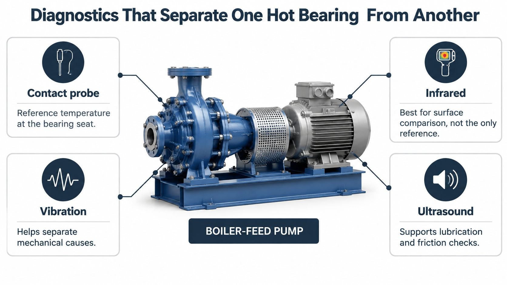
Diagnostics That Separate One Hot Bearing From Another
A confirmed temperature on the boiler-feed pump names the symptom. The mechanism behind it could be starvation, over-greasing, misalignment, or heat conducted in from the process, and each needs a different tool to prove. Judge the reading against that bearing's catalog limit, its own baseline, and its rate of rise before deciding it is even abnormal for that position, because a housing alarm alone is not a diagnosis.
| Method | Fault signature to look for | What it still cannot prove |
|---|---|---|
| Contact probe at the bearing seat | Housing temperature above baseline, plus its trend | Inner-ring temperature or the mechanism behind it |
| Infrared thermography | Drive end hotter than the opposite end, the sister pump, or the cooler outlet | Absolute metal temperature on a reflective surface |
| Velocity vibration | Amplitude at running speed pointing to imbalance, misalignment, or looseness | Early race damage or grease condition |
| Enveloped acceleration | Repetitive impacts from a developing race or rolling-element defect | Lubricant chemistry |
| Ultrasound | Rough, rising friction signature from rubbing or starvation | Remaining bearing life |
| Oil or grease analysis | Trending wear metals, water, viscosity shift, or varnish | Alignment or electrical fluting |
| Motor current signature analysis | Rotor defects or electrically driven bearing current | Mechanical preload or a cooler fault |
For this pump, infrared earns its place early: comparing the drive and opposite ends, checking the sister pump, and scanning the cooler and nearby process piping can show whether the heat is generated in the bearing or arriving from somewhere else. It cannot read the inner ring, and shiny surfaces produce unreliable numbers, so treat it as a comparison tool.
Velocity vibration picks up imbalance, misalignment, and looseness, which explains most hot-bearing calls where the machine itself has changed. When the temperature climbs on steady duty, enveloped acceleration for bearing fault detection isolates the repetitive impacts a developing race or rolling-element defect produces, often while the overall velocity spectrum still looks quiet. That single point, taken at the hot location, is what separates a mechanical rub from early bearing damage.
Treat the grease gun as a suspect until the mechanism is proven. Take an ultrasound reading before adding or removing grease: a rough friction signature that settles after a measured shot points to starvation, while one that worsens points to a cavity that is already full. For an oil-fed bearing, a sample can test wear metals, water, viscosity, varnish precursors, and contamination. Steam-turbine oil should be assessed against ASTM D4378 rather than by color, and babbitt wear metals belong on the same trend as the bearing's metal temperature and shaft orbit.
Grease life depends on time at temperature, and a single peak understates the damage. SKF's grease selection guidance identifies about 100°C at the hottest bearing ring as a practical upper limit for standard greases; even short exposure above a grease's high-temperature performance limit cuts grease life. A temperature alarm alone cannot separate starvation from over-greasing or mechanical rubbing. It needs vibration, lubricant condition, speed, load, and maintenance history beside it.
Forge Reliability performs lube oil analysis to track bearing wear metals and oil condition. Before anyone changes the pump's bearings or alignment, the minimum evidence is a confirmed contact temperature, one vibration point with envelope data, and a grease or oil sample.
Causes of High Bearing Temperature
A 90°C housing reading is only a clue. Decide it against that bearing's catalog limit, its own baseline at the same load and ambient, and the rate of rise over the last hour or shift. A packed grease cavity, a tight locknut, a blocked oil cooler, and a contaminated seal can land on the same number while needing different work. Treat added grease as a suspect until the mechanism is proven.
| Pattern | Likely mechanism | First check | Wrong move |
|---|---|---|---|
| Temperature rises for 1–2 days after greasing, then falls | Grease redistribution | Quantity, speed, and purge path | Add another shot |
| Housing packed full on a fan or pump | Churning because excess grease can't escape | Relief, drain, and grease bleed rate | Fill the cavity further |
| Fast climb in a dusty, wet, or coal-handling area | Ingress or lubricant collapse | Seals and a grease or oil sample | Relubricate over the contaminant |
| Both ends hotter after a load increase | Overload, speed, or ambient change | Amps, flow, and duty against the nameplate | Change the bearing first |
| One end hot with high 1× vibration | Misalignment, soft foot, or runout | Alignment and shaft runout | Add lubricant |
| Hot after a rebuild or locknut work | Preload, tight fit, or CN clearance where C3 is required | Clearance, drive-up, and shaft-to-housing temperature difference | Loosen random bolts |
| Oil-fed gearbox, compressor, or pump climbs as cooler outlet temperature rises | Low flow, wrong viscosity, or fouled cooler | Level, filter, viscosity, and cooler approach | Hose down the housing |
| Motor bearing near a variable-frequency drive | Possible fluting, or ordinary friction | Shaft voltage and current signature | Blame electricity from temperature alone |
| Turbine journal metal temperature rises with orbit size | Babbitt wear | Orbit trend and metal temperature together | Rely on a housing-only alarm |
A rise after greasing can be a redistribution transient, especially when surplus grease is churning in a restricted cavity. In fan service, a full housing without an effective escape path traps grease and adds frictional heat. For those applications, SKF's bearing-failure material gives a practical screen: use grease that bleeds at least 3% of its oil over seven days at normal bearing operating temperature (SKF's bearing-failure guidance).
Dust, water, food residue, coal, and process debris change the evidence fast. In 2025 tribology testing, coal particles drove bearing temperatures near 100°C in one test, smaller particles increased friction and heating, and a sensor-integrated plain bearing under lubricant failure gained 10.2°C within five seconds compared with 2.8°C without failure. Check seals, purge paths, and a lubricant sample before another relubrication cycle.
Heat can also feed itself. As lubricant warms, viscosity and film thickness drop, mixed friction rises, and the bearing makes more heat. On a hot shaft in a cooler housing, differential expansion can consume internal clearance and create preload. That is why a C3 clearance can be correct on some hot-running shafts while CN is correct elsewhere; match the class to the equipment design and the measured shaft-to-housing temperature difference.
For steam-turbine journal bearings, increasing shaft orbit size with higher bearing metal temperature is a key symptom of wear. The orbit describes shaft motion inside the bearing, so trend it with metal temperature instead of relying on a housing-only alarm. When grease condition is part of the vibration picture, vibration control insights from Intech Corporation is a useful reference for relating lubricant state to shaft motion. For recurring damage patterns, a structured bearing failure analysis helps connect the symptom to the failure mechanism.
One electrical caution: a 2024 study of rolling-element bearings lubricated with gear oil measured an average bearing temperature of approximately 99 ± 3°C when no electric current was applied (the study in Tribology Transactions). Temperature alone leaves variable-frequency-drive fluting unproven; confirm shaft voltage and current signature before assigning that cause. Relubricate only when the evidence points to starvation or an overdue interval. A cause is credible when it explains the limit, the baseline, the rise rate, and the second measurement.
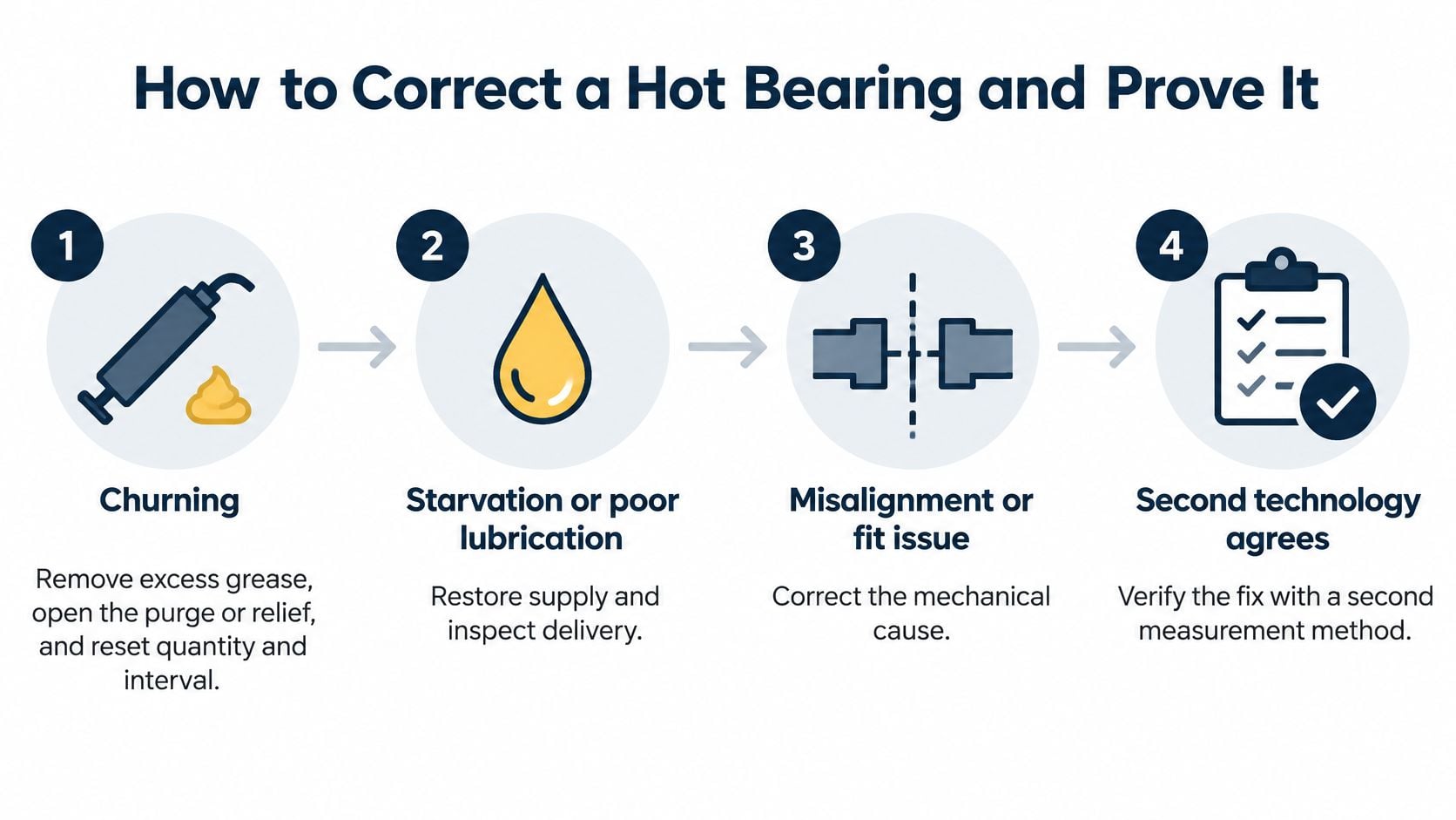
How to Correct a Hot Bearing and Prove It
A repair should follow a confirmed cause and a second diagnostic result that supports it. On the boiler-feed pump, clearing a grease blockage won't correct a cooler problem, and replacing a bearing won't resolve preload from a tight fit. Correct the mechanism, then check whether the bearing returns to its own baseline under comparable duty. Until the mechanism is proven, treat added grease as a suspect; extra lubricant raises churning losses and can mask the fault for a shift or two.
- For churning, remove excess grease and restore the escape path. Open the purge or relief, then reset grease quantity and interval so surplus lubricant can leave rather than continue to churn.
- For starvation or poor bleed, restore the specified lubricant supply. Use a compatible grease or oil with the required base-oil viscosity; confirm compatibility before changing products, then trend temperature rather than immediately pumping in more.
- For an oil-fed compressor, gearbox, or pump, correct the whole oil path. Verify level, viscosity, filtration, and circulation together, because a thin or interrupted film can allow metal-to-metal contact.
- For inadequate cooling, check the circuit before treating the housing. Inspect cooler approach, fouled tubes, and cooling-water quality; add circulating oil or an auxiliary cooler only if the existing system can't reject the heat.
- For mechanical preload, correct the fit and alignment. Resolve misalignment, soft foot, and runout, then address locknut drive-up or an excessively tight fit. Measure the shaft-to-housing temperature difference while the machine runs; a large differential shows how much the shaft has grown into the housing and whether the installed clearance is still adequate under those conditions.
- For confirmed electrical fluting, address the current path. Correct shaft voltage or use an insulated bearing where the design calls for one; swapping the bearing without fixing the cause invites repeat damage.
- Verify the repair at matching load and speed. Compare the housing temperature with the sister end and original baseline, check that velocity and envelope readings are stable or falling, and review a clean lubricant sample. Stop the machine if the trend continues with noise, rough turning, discolored grease, leakage, or seal damage.
Each of these corrections breaks the thinning-film feedback loop that turns a warm bearing into a seized one. For an oil-lubricated compressor or turbine gearbox, oil-lubrication guidance supports checking both heat generation and heat removal, including oil condition, circulation, and cooler performance.
A repair is proven when the pump returns to a temperature comparable with its sister machine at the same amps and duty, and vibration stays stable across repeat checks. For future rebuilds, document the bearing's fits, clearance, alignment, and lubrication requirements using a consistent bearing selection and installation process. I hold the verdict open until the bearing has logged enough run time at comparable duty to show the trend is holding at its own baseline.
Monitoring Tips That Catch the Next Rise
Set alarms from the bearing's own numbers. Before the next rise, build each machine's alarm logic from the catalog limits covered in the limits section, the bearing's measured baseline, and its rate of rise. A setpoint copied across every asset will trip late on a tight-clearance bearing and false-alarm on one that runs warm by design.
- Match the measurement to the baseline. Measure the same bearing seat at comparable load, speed, and ambient conditions so a real change can be separated from a change in duty.
- Track the rate of rise. A sudden increase on steady duty is more concerning than a stable reading that reflects a different normal operating condition.
- Respect the transient window. Allow for the expected temperature rise during the first one or two days after start-up or grease relubrication, then act on a persistent rise beyond that window.
- Hold the measurement point steady. Keep the sensor on the same bearing seat; a new paint spot or a reading taken off a guard won't produce a valid trend.
- Refuse the quick fix. Don't apply water or add grease to buy a shift. Either action can hide the mechanism without resolving it, and added grease stays a suspect until the cause is proven.
- Cover critical assets between rounds. Pair every temperature point with vibration. For critical pumps, induced-draft fans, compressors, and turbines, continuous vibration at each bearing location can detect blade erosion, imbalance, and bearing degradation between manual rounds.
- Write the maintenance history down. Log grease type and quantity, delivery method, and temperature before and after maintenance in the CMMS. Rebuild setpoints when lubricant, clearance class, or duty changes.
A critical asset's one-page alarm sheet should name the sensor location, baseline, warning limit, trip limit, rate-of-rise limit, transient window, and person responsible for acting. Set each limit for the equipment: a motor needs a catalog limit and a nameplate-matched baseline; a pump or fan needs a bearing-seat baseline at comparable flow or airflow; a gearbox or compressor needs oil-outlet temperature considered with cooler approach; and a steam-turbine journal needs metal temperature paired with shaft orbit rather than a fixed Celsius trip.
For sound-based checks that complement vibration and temperature routes, use a defined ultrasonic bearing-monitoring and acoustic-lubrication practice. Continuous coverage earns its place on assets whose failure consequences justify it; on the rest, a disciplined route with a stable measurement point catches the next rise early.
Book a Free Reliability Assessment
The boiler-feed pump's 92°C reading may have come from one grease mistake, or it may expose a gap in the site's monitoring and maintenance program. The reading is actionable when it's confirmed against both the pump's own baseline and its relevant equipment limits, a second diagnostic method supports the cause, and the repair holds under the same load and speed.
If this pump returns to baseline and its lubricant sample is clean, one verified repair may be enough. If several pumps, fans, gearboxes, or steam-turbine journals keep running hot, or the site lacks useful thermography, oil analysis, or vibration coverage, a free reliability assessment can help prioritize the problem. Forge Reliability can rank hot assets, establish bearing-specific limits from catalog information and operating baselines, and recommend route-based or continuous monitoring where the equipment justifies it.
Bring the last month of bearing temperatures, the lubricant specification, and one vibration route to the assessment. To start, visit Forge Reliability.