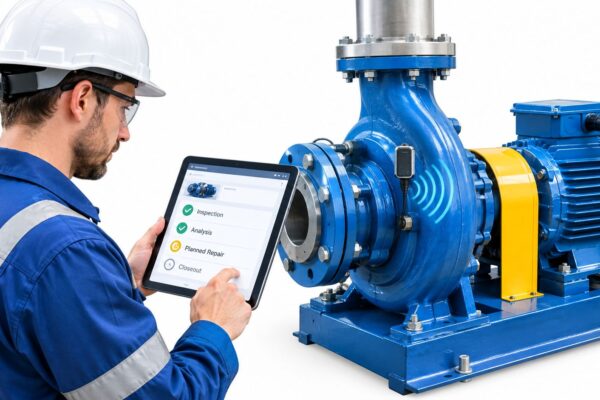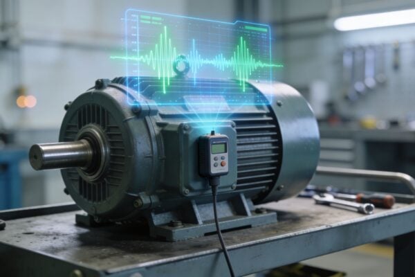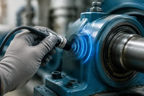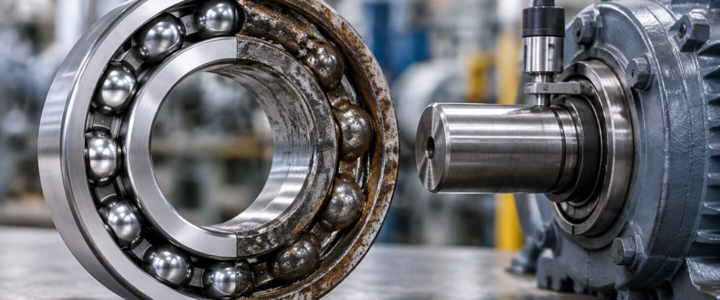
A motor comes out for the second time in nine months. The replacement bearing matched the bore, the load looked light, and overall vibration stayed acceptable until the last week. On the bench, though, the raceway shows smearing at one end, dark grease at the other, and a faint washboard pattern that doesn't fit simple fatigue.
That's the trap with a radial deep groove ball bearing. Axial preload, minimum load problems, contamination, and electrical damage can all raise temperature and vibration, but each one needs a different fix. Replacing the bearing without separating those mechanisms usually buys a repeat failure. The practical work is reading the evidence in combination, checking float, load, lubricant, and shaft voltage before ordering a like-for-like spare.
Table of Contents
- Anatomy and Load Ratings of a Radial Deep Groove Ball Bearing
- Failure Mechanisms That Wear Out Radial Bearings
- Diagnostic Signatures from Vibration, Oil and Ultrasound
- Axial Load, Thermal Growth and Minimum Load Traps
- Contamination, Lubrication and Electrical Damage
- How to Mount and Remove a Radial Bearing Safely
- Monitoring Strategy and Free Reliability Assessment
Anatomy and Load Ratings of a Radial Deep Groove Ball Bearing
A designation on a drawing gives you the bore, the envelope and little else. The bearing itself has five parts a technician can inspect. The inner ring fits the shaft, the outer ring fits the housing, and both rings carry a deep raceway, the groove the balls roll in. The ball set carries load between the rings. The cage, also called a retainer, holds even spacing so balls don't rub each other.
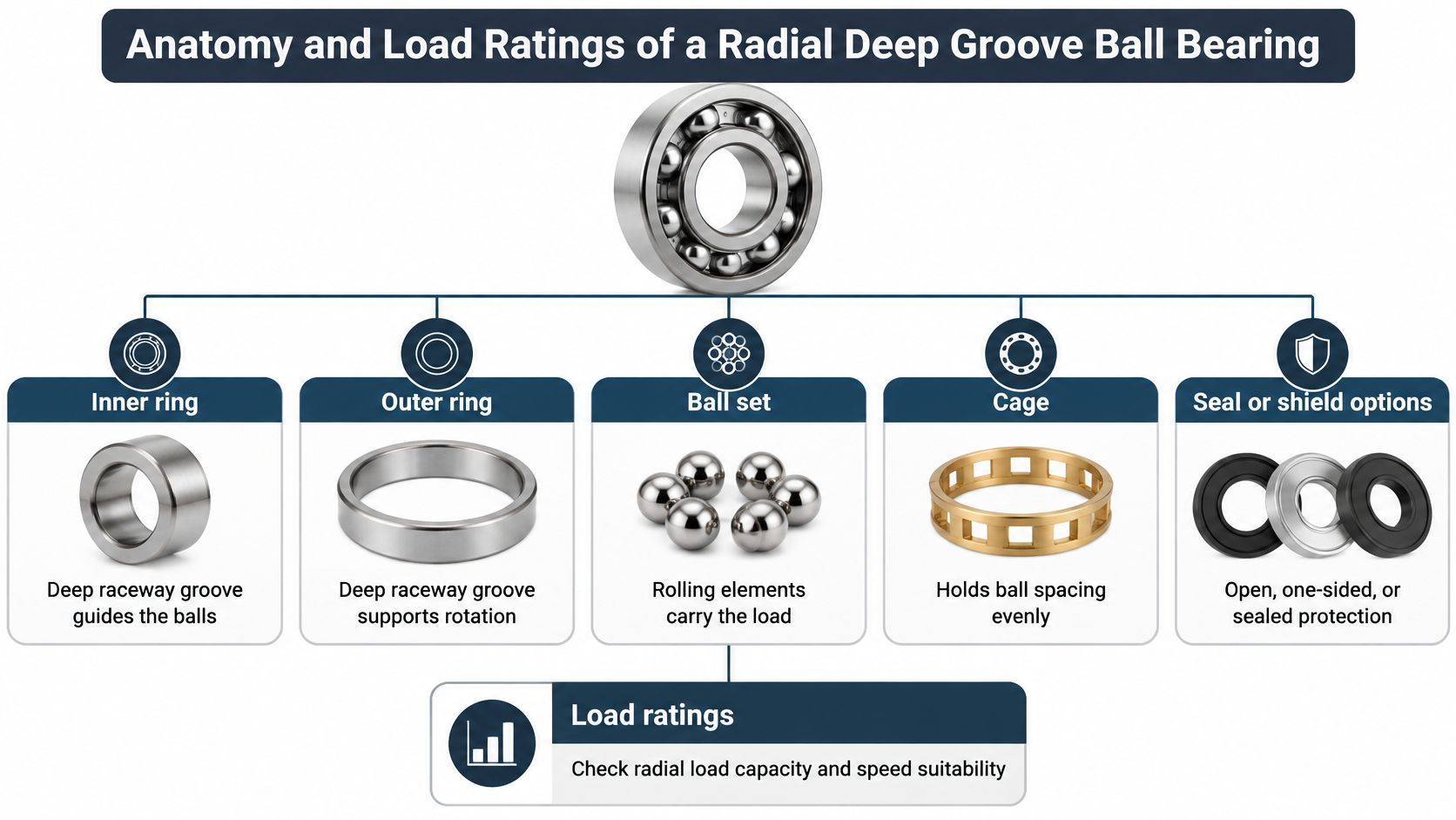
Radial load acts perpendicular to the shaft, such as belt pull or rotor weight. Axial load acts along the shaft. The deep groove lets this bearing carry radial load as its main path and moderate axial load in either direction, which explains its use in motors, pumps, fans, and gearboxes. Closures matter too. Bearings come open, with no closure, one-sided sealed, or two-sided sealed. That choice sets whether external lubrication is possible and how well dirt stays out.
What the Ratings Mean in Service
The basic dynamic load rating is the constant load at which 90 percent of identical bearings reach one million revolutions, known as L10 life, the statistical fatigue life used for rotating applications. The basic static load rating corresponds to a permanent deformation limit at the most heavily loaded ball contact, relevant during shock, slow oscillation, or long dwell under load. Neither rating is a breaking load. Both feed a life and safety check against the actual duty cycle, including starts, axial components, and speed.
What the ratings leave out matters as much. They assume clean lubricant, correct mounting and a load path that does not pin the bearing axially. A 6205 that clears its L10 calculation can still smear a raceway inside a year once the housing grows and the outer ring loses its float.
| Designation | Dimensions | Basic dynamic load rating | Basic static load rating |
|---|---|---|---|
| 6205 | 25 mm bore, 52 mm OD, 15 mm width | 14.0 kN | 7.8 kN |
| 61822 | Bore code 22 sets bore size per catalog | 6,317 lbf | 5,845 lbf |
The figures above are the catalog ratings for each designation, and manufacturers publish the pair side by side rather than one without the other. SKF's specification for the 61822 single-row deep-groove ball bearing shows the format to expect when you look up any size, with metric and inch-series catalogs quoting in their own units.
Practical rule: Read the designation from the nameplate or drawing, look up bore, width, and both ratings, and confirm the rating before ordering.
The sizing rule is straightforward. Confirm that calculated life covers the actual duty, not only that the bore fits the shaft. Adjacent sizes look similar on a shelf but behave differently in service, so comparing a candidate against a known reference such as the 6202 bearing size guide lets a planner sanity-check dimensions before a purchase becomes a shutdown surprise.
Failure Mechanisms That Wear Out Radial Bearings
Rolling fatigue is the baseline mechanism. Repeated contact stress eventually initiates subsurface cracks that break out as flaking or spalling, small pieces of raceway material lifting away. Overload and misalignment don't create a new physics, they consume calculated life faster by concentrating stress on fewer balls or one edge of the raceway.
Other mechanisms depart from that pattern in recognizable ways. Brinelling leaves evenly spaced indentations from impact during handling or hammer mounting. False brinelling looks similar but comes from vibration while the machine sits stopped, wearing the contact points without rotation. Smearing shows torn, streaked metal where balls skid instead of roll, usually under light load at high speed or during rapid acceleration.
| Mechanism | Typical cause | Early sign |
|---|---|---|
| Rolling fatigue | Overload, misalignment, end of calculated life | Rising vibration at bearing defect frequencies |
| Contamination | Dirt, moisture, abrasive particles entering through seals | Higher high-frequency noise, wear debris in oil |
| Lubrication breakdown | Wrong grease, overgreasing, dry running | Rising temperature, higher ultrasound level |
| Electrical fluting | VFD shaft currents, stray current | Corrugated raceway, high-frequency vibration |
| Axial preload | Thermal growth against a locked shaft | Rising temperature, near-zero shaft-end float |
| Insufficient minimum load | High speed with light radial load | Ball skidding, smearing, cage wear |
Two Field Patterns Worth Recognizing
Say a 1.5 kW washdown conveyor drive loses bearings every four months. Investigation finds the shaft misaligned by 0.5 mm over a 300 mm span, edge-loading the raceway on every revolution. A premium bearing won't fix that geometry. Alignment correction and a fit check will.
Contrast a VFD-driven 75 kW pump motor, where VFD means variable frequency drive, the electronic controller that varies motor speed. The raceways show a corrugated, washboard pattern called fluting, caused by shaft currents discharging through the lubricant film. The load calculation was never the problem. Shaft grounding or an insulated bearing position is.
Most field failures combine two mechanisms. Contamination raises friction and temperature, temperature thins the lubricant film, and the thinned film then accelerates surface fatigue.
A usable triage routine keeps the team honest. Name the dominant mechanism first, inspect the raceway pattern second, and check lubricant and seals third. Then record operating context, including speed, load, ambient conditions, and washdown frequency, so the next failure can be compared against facts rather than memory.
Diagnostic Signatures from Vibration, Oil and Ultrasound
Each technique here answers one narrow question. The useful discipline is picking the one that fails first for the mechanism you suspect, rather than running all four on every asset and reading whatever looks worst.
Vibration envelope analysis demodulates high-frequency impacts into an envelope spectrum, where repetitive impacts from a localized defect become visible. Peaks appear at bearing defect frequencies, the calculated rates at which balls pass a defect on the outer race, inner race, ball, or cage. Those peaks typically rise weeks before the overall vibration level moves, which makes envelope trending the sharpest tool for early fatigue.
Lube oil analysis answers a different question. It tracks wear metals such as iron and chromium, water content, viscosity, and lubricant breakdown. A rising envelope peak against a flat iron trend points toward a localized surface defect. Rising iron across the board suggests general wear shedding material into the oil, and a step change in water or viscosity indicts the lubricant before the metal ever moves. Forge Reliability performs lube oil analysis to track bearing wear metals and oil condition, which gives maintenance teams that second, independent line of evidence.
Ultrasound, measured in decibels with a contact sensor at constant load, responds to friction before heat builds. A bearing starved of grease gets louder ultrasonically while its temperature may still look normal, so ultrasound is usually the earliest sign of lubrication starvation. Compare every reading against a baseline taken at the same speed and load, because an absolute decibel number without context misleads.
Temperature trending and the shaft-end float check cover the mechanical side. Shaft-end float is the small axial movement available when the shaft is pushed end to end by hand at standstill. A sustained temperature rise above baseline suggests preload or lubrication trouble, and near-zero float at a cold start tells the technician the shaft has nowhere to grow when it warms up.
| Technique | What it shows | Early warning |
|---|---|---|
| Vibration envelope analysis | Outer race, inner race, ball and cage defect frequencies | Defect peak rising above its baseline |
| Lube oil analysis | Wear metals, water, viscosity and lubricant breakdown | Rising iron or chromium trend |
| Ultrasound (dB) | Friction and lubrication starvation | Rising dB at constant load |
| Temperature trending | Preload and lubrication condition | Sustained rise above baseline |
| Shaft-end float check | Axial preload | Near-zero float at cold start |
A Worked Separation of Fatigue From Contamination
A 110 kW pump motor shows its outer race defect peak rising from 0.2 g to 1.1 g over six weeks, where g is acceleration due to gravity, the unit for envelope amplitude. Oil iron stays flat across the same samples. That combination points to fatigue spalling on one raceway, not contamination, because abrasive wear would push wear metals up alongside vibration.
The reverse pairing reads just as cleanly. Rising ultrasound with rising iron means the lubricant film is failing and surfaces are wearing, which sends the team to grease condition, water, and seal integrity rather than a fatigue life recalculation.
Then there is the pattern that fools people, because it produces heat and noise without a defect frequency: temperature climbing, ultrasound normal, no envelope peaks. That is axial preload or skidding under light load, and fresh grease will not shift it. Same symptom family, three different mechanisms, three different fixes.
Diagnostic discipline: Never call a failure from one trend. Require two independent signals that agree, then confirm with a physical check such as float, grease appearance, or seal condition.
That discipline costs one extra measurement. It saves the far larger cost of replacing a bearing, restarting, and watching the same signature rebuild within a quarter because the actual mechanism was never touched.
Axial Load, Thermal Growth and Minimum Load Traps
A load below the catalog rating is not automatically safe. Two opposite traps sit below that threshold, and both leave heat, cage wear, and a work order history that reads like ordinary overload. The evidence has to separate them before a team replaces a bearing that was never the underlying problem.
The first trap is unintended axial preload, an axial force locked into the bearing arrangement before the machine starts. A deep groove bearing carries combined radial and axial load, but axial displacement beyond available internal clearance has to be absorbed somewhere, normally by letting one outer ring float in its housing. The SKF guidance on deep groove ball bearings for high-temperature applications covers the bearing variants and clearance choices used when heat and displacement must be managed together. Steel expands as it warms, so a shaft that runs hotter than its housing grows along its length. If both bearings are clamped axially, that growth becomes preload, preload becomes friction and heat, and heat drives early fatigue.
The Opposite Trap at Light Load
At high speed with light radial load, centrifugal force and gyroscopic effects can make balls slide instead of roll. Minimum load is the smallest applied load that keeps balls in rolling contact with the raceways. Below it, balls skid entering the loaded zone, producing smearing, cage pocket wear, and temperature rise even though the applied load sits far below the catalog rating. Electric motors, fans, pumps, and high-speed spindles are the usual victims because they run fast and lightly loaded by design.
A 3,600 rpm light-duty fan motor runs hot with polished, streaked raceways and a worn cage. Float checks normal, grease looks clean, and no defect frequencies dominate the spectrum. That pattern fits skidding, not preload. The distinction between the two loading directions is spelled out in the radial versus axial load explanation, and it matters here because the fixes oppose each other. Preload needs float restored. Skidding may need load added, a different clearance, or a spring preload arrangement.
Catalog thermal reference speed needs the same skepticism. It is a conditional reference value, not a universal speed limit. Reference calculations are tied to a moderate ambient, a defined bearing and housing interface temperature, a specified lubricant viscosity, normal clearance, and a light radial load. A hotter plant, thicker grease, or tighter clearance invalidates the headline number.
Contamination and electrical damage can also show up as heat and cage wear, but grease condition, raceway patterns, and the voltage between shaft and ground separate them from these two load traps.
The decision sequence is short. Check shaft-end float cold and warm, compare the actual load against the manufacturer's minimum load guidance, then inspect for smearing if the bearing comes out. Adjust housing float or the preload arrangement based on which trap the evidence supports, not on which fix is faster.
Contamination, Lubrication and Electrical Damage
A food plant lost a bearing early because two incompatible greases were mixed during a washdown routine. The thickeners, the soap-like agents that give grease its structure, reacted; the blend softened and leaked past the seals; and the bearing failed despite a load rating with margin to spare. The first read pointed at water ingress. The second pointed at overgreasing. Only the relubrication record and the grease appearance separated them, which is the recurring problem in this failure family: contamination, lubricant quantity, and electrical discharge leave overlapping clues.
Start with what the bearing arrives with. Sealed bearings are factory lubricated, while open or one-sided sealed bearings need oil or grease before service, and moisture and contaminants have to stay out in either case, as the Timken deep groove ball bearing catalog states. The field sequence below uses evidence a team can collect in one visit. It starts with the lubricant because it is the cheapest thing to rule out and the easiest to disturb.
A Four-Step Decision Path
- Grease condition first: Rising ultrasound, the high-frequency friction noise picked up by an ultrasonic meter, plus dark or dry grease calls for a check of grease condition and the quantity last applied. Overgreasing churns the grease and overheats the bearing; undergreasing starves it. Both raise friction noise, so the quantity record matters as much as the sound.
- Water second: Milky grease or a sample that shows water points to seal ingress. Inspect seal lips for wear or damage, and check whether washdown spray hits the seal directly. A damaged lip turns a washdown routine into a water injection system.
- Electrical third: A corrugated raceway pattern, called fluting, or high-frequency vibration on a motor driven by a variable frequency drive (VFD) calls for a shaft voltage measurement. Shaft voltage is the electrical potential between the shaft and ground. Discharge craters and fluting confirm electrical damage that no grease change will cure.
- Cage last: A cracked or deformed cage at high speed calls for a check of cage type against its speed rating. Conventional crown-shaped plastic cages can deform above their limit, risking pocket fractures or contact with the outer ring.
The technique behind step one, listening while greasing in small shots, is covered in the ultrasonic bearing monitoring and acoustic lubrication guidance. That approach prevents pumping until grease purges from the seal, a common error that often means the cavity is already packed and the seal lip is damaged.
Treat the list as a sequence of eliminations, not a menu. A washdown pump can take in water and get overgreased in the same week, and the overgreasing masks the water because fresh grease pushes the milky evidence out of sight. Electrical damage can also coexist with a dry running grease that has lost its film. The repair that lasts addresses the mechanism that produced the first damage, then removes the conditions that let the second one start. Replacing the bearing before that separation only resets the clock.
Upgrading to a higher load rating won't fix poor sealing, incorrect lubricant quantity, stray current, or mounting damage. It only installs a more expensive victim.
Close the loop with a sampling plan. Sample grease and oil on a fixed schedule, record the type and quantity of every relubrication, and photograph seal condition at each visit. In dusty aggregate or chemical service, shorten the interval. Ingress rates should set the schedule, not calendar habits.
How to Mount and Remove a Radial Bearing Safely
Most radial bearings that fail inside the first year were damaged before they ever turned. The injury happens in the press, the heater or the hammer, then surfaces months later as a defect frequency or a spall that gets blamed on the lubricant. Each stage below exists to prevent one specific injury, and skipping it just moves the failure date forward.
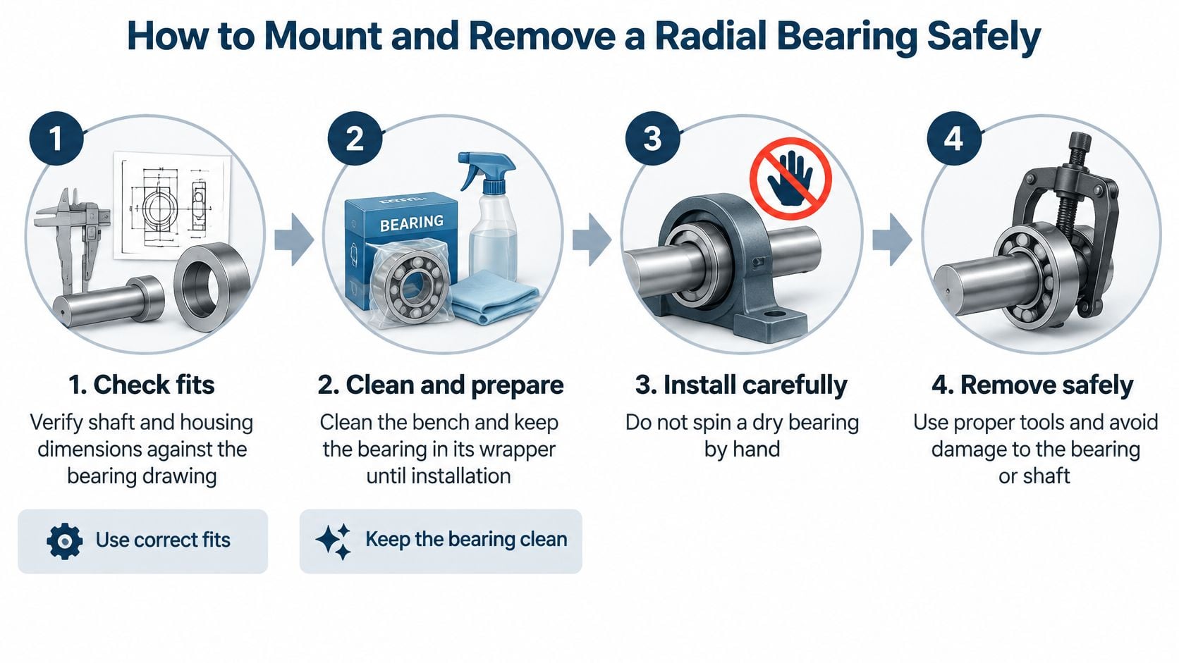
Prepare the seat before the wrapper comes off. Measure shaft and housing dimensions against the drawing first. A fit describes how tight or loose a ring sits on its seat; an interference fit means the shaft is slightly larger than the bore so the ring cannot creep under load. Seats worn oval, or polished by a ring that has been spinning, defeat a perfect installation and no amount of careful heating recovers them. Keep the bench clean and leave the bearing wrapped until the last moment. Never spin a dry bearing with compressed air, because unlubricated balls skid and the cage can burst.
Heat, never hammer. Warm the bearing in an induction heater, staying under the temperature cap stated on the bearing drawing or in the manufacturer's mounting instructions. For a typical greased deep groove ball bearing that cap sits near 120 °C, and it has to be confirmed against the drawing rather than assumed, because sealed and pre-greased variants tolerate less. The bore then expands enough to slide on by hand. Hammer blows dent the raceways at ball spacing, which is brinelling, and those dents become spalls once the bearing runs loaded.
Send the force through one ring only. With a shaft interference fit, press on the inner ring using a sleeve that contacts its face squarely. Pressing the outer ring transfers installation force through the balls and damages both raceways before first rotation. Fitting into a housing reverses the rule: press the outer ring.
Set axial location, then prove the float. Seat the bearing against its shoulder, install spacers or the locknut per the drawing, then measure shaft-end float. Skipping the float check is how thermal preload gets built in at the bench. A bearing set with no room to grow runs hot, and its axial load signature is easily mistaken for a misalignment or minimum-load problem when the root cause was a shim left out.
Charge grease to the marked quantity. Fill to the amount on the housing or work instruction and record type and quantity. Overgreasing raises running temperature through churning, and mixing thickener types invites the incompatibility failure that ends food-plant bearings in weeks.
Pull on the interference ring. Removal mirrors installation. Grip the ring carrying the interference fit and pull straight with a puller. Pulling through the outer ring loads the balls in reverse and can crack a cage or score the shaft seat, and a scored seat guarantees a loose fit on the replacement.
The 6205 as a Worked Example
On a 25 mm shaft, the 6205's 25 mm bore sets the fit class, so the shaft tolerance, not technician feel, decides heating time and mounting force. If the heated bearing will not slide home, stop and remeasure rather than reaching for a hammer. Force at that stage always leaves evidence, and the evidence returns as a defect frequency long after everyone has forgotten the installation.
The wider selection and installation context, including clearance choice and housing preparation, is set out in the bearing selection and installation for maximum life guidance. Pairing that preparation with the steps above closes most installation-related failure modes.
Log the job properly every time: bearing designation, clearance class, measured fits, heating temperature, grease type and quantity, and final float. That record is what separates hammer brinelling from the false brinelling a standby machine picks up from nearby vibration, and it turns the next failure investigation into a comparison instead of a guess.
Monitoring Strategy and Free Reliability Assessment
Set monitoring coverage by criticality, and revisit the plan when operating conditions change. Route-based monitoring collects vibration, ultrasound, and temperature on a fixed schedule, typically weekly for critical assets and monthly for less critical ones. It suits plants with limited instrument budgets. Continuous monitoring watches bearing locations at all times and catches fast-developing faults between routes, which suits high-speed or high-consequence equipment. Forge Reliability deploys continuous vibration monitoring at all bearing locations to detect blade erosion, imbalance, and bearing degradation.
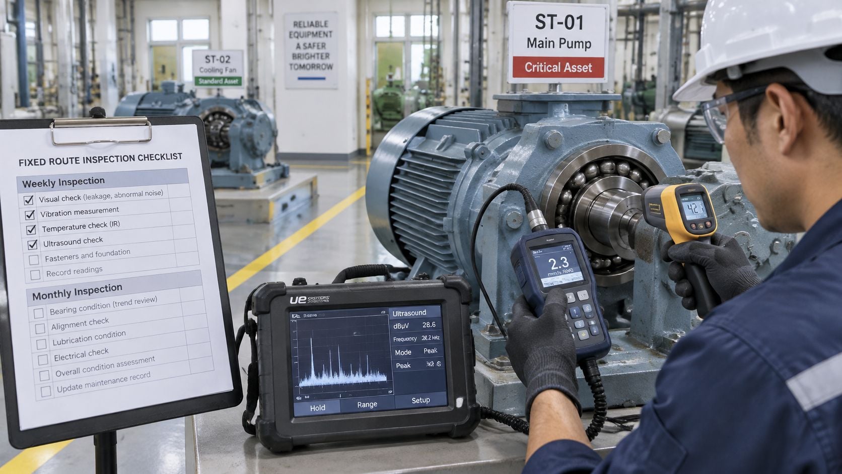
Four criteria decide the split: asset criticality from a risk ranking, the cost of one hour of unplanned downtime, failure history, and speed. A slow, spared pump with cheap downtime earns a monthly route. A sole production fan running near its speed limit earns continuous coverage quickly. Use the data to separate a load problem from lubrication, contamination, or electrical damage before anyone pulls the bearing. A single rising vibration trend rarely identifies the mechanism, so compare vibration with ultrasound and temperature against the operating state.
Criticality Outranks Bearing Price
Take the 6205 bearing on a 1.5 kW conveyor drive in a food plant. The bearing itself is inexpensive, but its failure stops the packaging line, so it ranks near the top on downtime cost. Plants that rank by component price under-monitor exactly these assets. Rank bearings by downtime exposure, and let unit price shape the spares strategy. The same cost trade-off appears outside industrial plants, where Simply Hospitality's low-price alternative makes the everyday low-price case. A low unit price only wins if disruption risk stays flat.
Start route-based coverage across the whole asset list, then move top-ranked motors and pumps to continuous monitoring once baselines and alarm levels are set.
That sequence builds the baseline data continuous alarms need, and it spreads early wins across the plant instead of concentrating instrumentation on a few showcase machines. Revisit the ranking whenever production rates, sparing, or washdown practices change. Criticality tracks operating conditions, so the coverage map should move with them.
Start with a free reliability assessment from Forge Reliability. The scope covers bearing arrangements, operating loads, and temperature and vibration data on the assets you rank highest, with a 24-hour response from plant-floor specialists. Request it first for the assets carrying the highest downtime cost, since those bearings repay correct diagnosis fastest.
Stop replacing radial deep groove ball bearings that were never the root problem, and let Forge Reliability review bearing arrangements, loads, lubrication, and vibration and temperature data to identify the dominant failure mechanism. The assessment is free and returns prioritized corrective actions for the assets costing the most downtime. Visit Forge Reliability to request the assessment and get a response within 24 hours.