
A bearing can pass the routine route, sound fine on a handheld check, and still fail hard before the next month's shutdown window. That's the part crews remember, because the failure rarely starts as a dramatic event. It starts as a change in friction, lubrication, or surface condition that hasn't yet shown up in temperature or vibration.
That gap is where ultrasonic bearing testing earns its place in a reliability program. The method grew into a field tool later than vibration-based maintenance, with the first published ultrasonic work on rolling bearings appearing in 2003 and the technique developing quickly after that doctoral thesis on rolling-bearing ultrasound. On plant floors, that matters because ultrasound is usually not the legacy standard. It's the complementary layer that catches friction and lubrication change before the bearing gets loud, hot, or obviously damaged.
Table of Contents
- Why Vibration Analysis Misses Early Bearing Failures
- Selecting Equipment and Establishing Baselines
- Sensor Placement and Scan Procedures
- Interpreting Signals and Setting Alarm Thresholds
- Integrating Ultrasound with Vibration and Oil Analysis
- Common Failure Modes and Maintenance Actions
- Next Steps for Your Reliability Program
Why Vibration Analysis Misses Early Bearing Failures
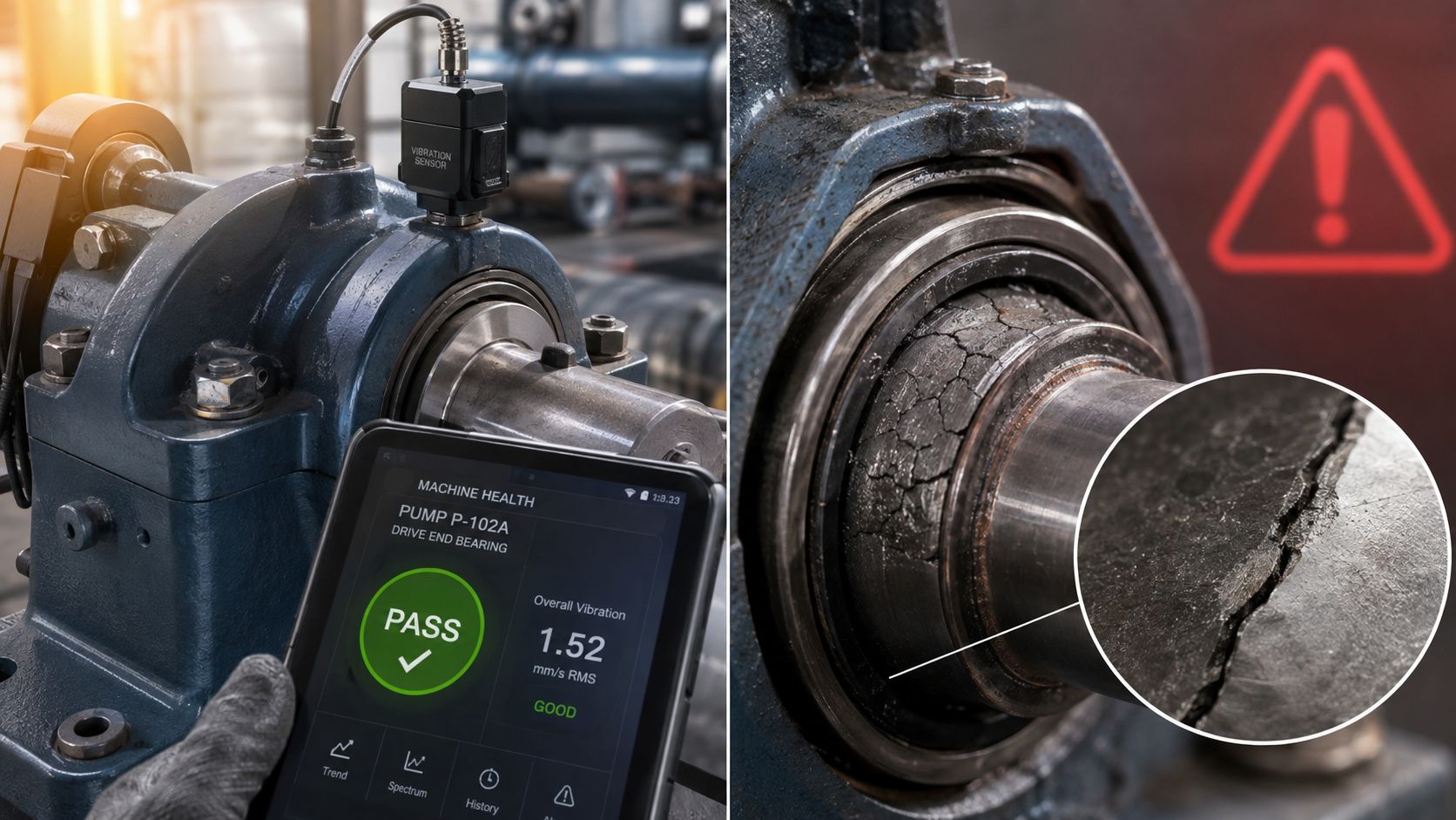
A common scene in a pump house goes like this. The monthly vibration route comes back clean enough to defer action, the bearing sounds normal at the walk-by, and three weeks later the pump is down with a bearing that's beyond field repair. The vibration file wasn't wrong. It was just early enough to miss the friction change that ultrasound would have seen first.
Vibration analysis is still a core tool, but it often becomes more decisive after defect energy grows into a clear pattern. Ultrasound looks at a different part of the failure curve. It is used to detect changes in friction, lubrication state, and incipient damage before those changes become obvious in temperature or vibration trends, which is why reliability teams use it as a complementary diagnostic rather than a replacement for vibration-based maintenance doctoral thesis on rolling-bearing ultrasound.
What ultrasound hears that vibration often misses
Ultrasound operates in the 20 to 100 kHz range in common industrial practice, so it picks up high-frequency stress waves from metal-to-metal contact, lubricant film breakdown, and early surface fatigue long before those signatures become obvious in the lower-frequency vibration spectrum. That difference is why a bearing can still look acceptable on vibration while ultrasound already shows an increasing friction signature. For a conveyor head pulley, a fan motor, or a centrifugal pump, the practical value is the same, which is earlier warning and more time to plan work.
Practical rule: if a bearing sounds different in ultrasound before it looks different in vibration, treat ultrasound as the early trigger and vibration as the confirmation layer.
The point isn't to choose one method and dismiss the other. It's to place each one where it's strongest. Vibration tells you a fault is maturing. Ultrasound often tells you the bearing environment is changing first, especially when lubrication is slipping or a load zone is beginning to wear.
For a reliability group trying to tighten its route program, a strong starting point is to pair ultrasound with a clear vibration workflow such as this vibration analysis bearing fault detection guide. Used together, the two methods give a more complete picture than either one provides alone.
Selecting Equipment and Establishing Baselines
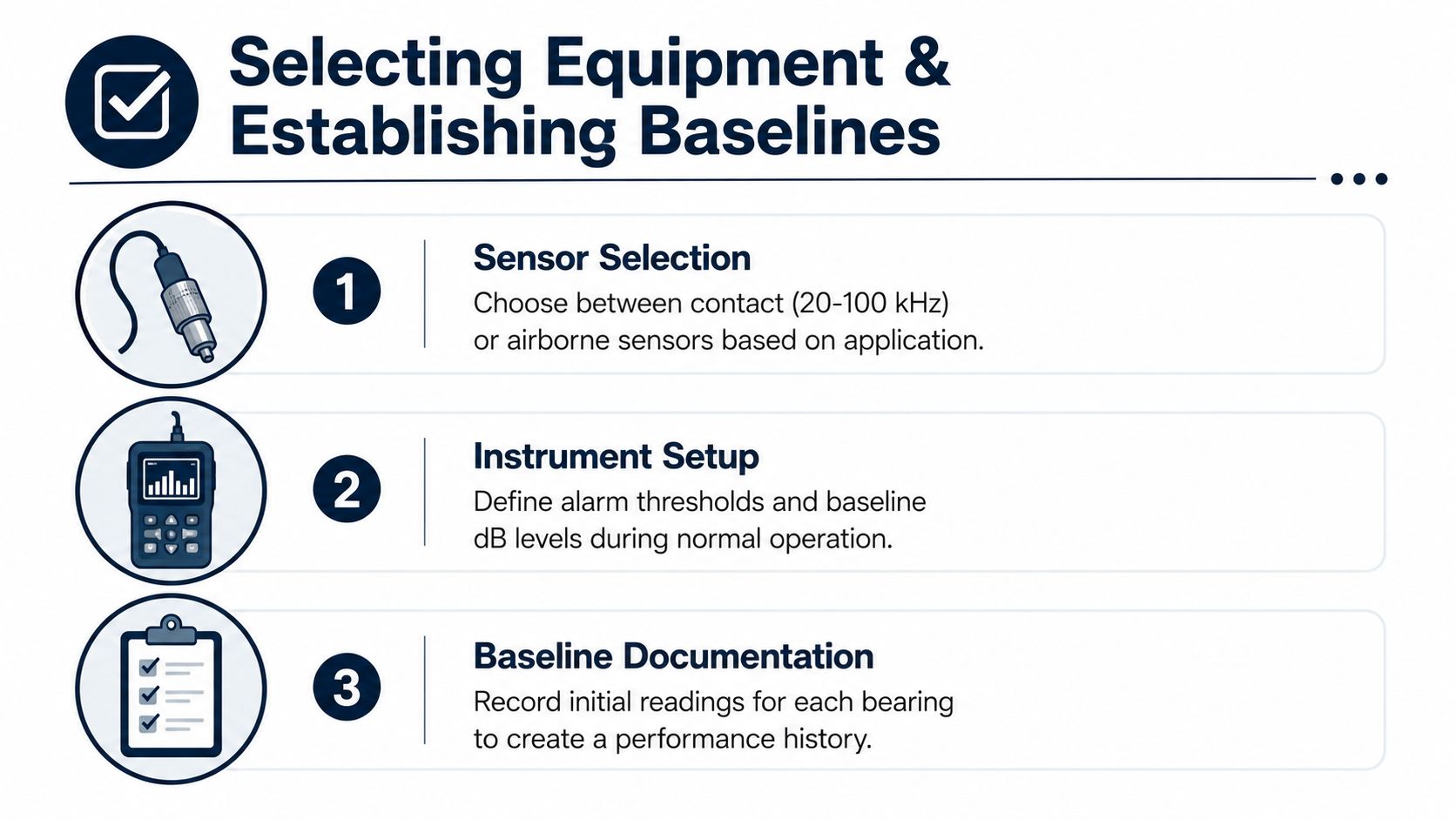
The hardware decision is less about buying the most sensitive instrument and more about buying the one your team can use the same way every week. In bearing work, the useful distinction is usually contact versus airborne sensing, because contact probes are better for repeatable route measurements while airborne methods are better suited to quick checks or access-limited locations. The instrument also needs a stable frequency setting and a readable dB scale so technicians can compare one visit to the next without guessing what changed.
Baselines are the real asset
A historical baseline turns ultrasound from a one-time inspection into a trend tool. The same bearing should be checked over time under similar load, similar speed, the same angle, and the same frequency setting so the change you see belongs to the bearing, not to the way the measurement was taken industrial ultrasound guidance. That matters more than an absolute number because a bearing at one plant and a bearing at another plant won't behave the same if the duty cycle, mounting, or lubrication regime is different.
A pulp-and-paper mill is a good example of why this discipline matters. When route technicians used inconsistent angles and switched between test points on the same housing, the team saw false alarms that looked like random friction spikes. Once they standardized the route, fixed the sensor angle, and documented the baseline for each bearing, the noise settled into a trend the planners could use.
What to document on day one
The paper trail doesn't need to be fancy, but it does need to be consistent. Record the bearing ID, location, normal operating load, normal running speed, sensor type, angle, and frequency setting. If the plant uses multiple shifts, the route card should also show who took the reading and whether the asset was at steady state.
A baseline that can't be repeated is just a note, not a diagnostic reference.
For teams building out a new program, the equipment selection should follow the application, not the other way around. A contact probe on a gearbox bearing under load gives a very different kind of information from a quick airborne scan on a guarded motor. The instrument needs to fit the access, the temperature, and the route discipline that the site can sustain.
A useful internal reference for that selection process is the ultrasound testing equipment overview, especially for teams deciding how much of the route should be handheld and how much should stay standardised. In the field, the winning setup is usually the one that keeps the same bearing, same test point, and same measurement habit intact month after month.
Sensor Placement and Scan Procedures
The biggest source of bad ultrasound data isn't the instrument. It's the way the sensor touches the machine. If one technician scans on the top of the housing, another scans near the load zone, and a third moves the probe while listening for the loudest spot, the resulting trend means very little. The scan has to be repeatable enough that a change in dB level reflects the bearing, not the operator.
Field geometry matters more than people think
For ball, roller, and sleeve bearings, the route should mark a fixed measurement point on the housing and keep the sensor angle the same every time. The practical discipline is simple. Keep the contact pressure firm but steady, avoid sliding the probe during the scan, and stay far enough from edges and guards that the reading isn't contaminated by structure-borne noise from nearby components. That approach mirrors the general ultrasonic principle of fixed measurement geometry used in other inspection work, where points, spacing, and calibration are controlled before measurement ultrasonic flaw detection example.
A chemical processing plant shortened scan time after it stopped hunting for the hottest or loudest spot on each bearing housing. Technicians marked the scan points, followed the same route sequence, and used the same contact location every visit. The route became faster because nobody had to re-decide where to measure, and the readings became easier to compare because the geometry never changed.
Field habit that pays off: scan the same place, the same way, every time, even when another spot sounds louder in the moment.
How to work around plant-floor realities
Access is rarely perfect. Bearings sit behind guards, near hot surfaces, or under pipe racks that make a clean angle difficult. In those cases, the rule is still consistency. If the bearing can only be reached from one side, use that side every time. If the route has to be done under load, keep the load condition steady enough that the technician isn't reading a moving target.
The route card should also note whether the bearing was ball, roller, or sleeve, because the housing response and noise character can differ. For a fan bearing, the scan may be quick and straightforward. For a loaded gearbox bearing, the technician may need more care to avoid false noise from adjacent gears or supports. A reference on vibration analysis sensors can help route designers think about mounting, accessibility, and repeatability in a broader condition-monitoring context.
Interpreting Signals and Setting Alarm Thresholds
A bearing can sound worse in the field than it reads on paper. Raw dB values only mean something when you compare them to a stable baseline, and that baseline has to come from the same asset under similar operating conditions. A rise in dB can point to insufficient lubrication, bearing damage, or a shift in speed or load. The first question is not, “What number is it?” It is, “What changed on this asset since the last valid reading?”
Why baselines matter
A baseline is the asset's normal acoustic fingerprint, captured after the machine has been checked under a known condition and the route has been repeated the same way. If the operating state changes, the reading changes too. That matters on machines with variable-speed drives, intermittent duty, or load swings, because a good bearing can look noisy when the process itself changes. For that reason, stable baselines are the asset, and they are also the reason a route note should include whether the machine was at steady load, ramping, or cycling.
The dB thresholds that matter in the field
Common industrial guidance treats approximate rises above baseline as practical indicators. Around +8 dB suggests insufficient lubrication, around +16 dB points to bearing damage, and around +35 dB signals critical failure. Those are trend comparators, not universal pass-fail limits, because the same dB rise does not mean the same thing on every bearing, and the right interpretation still depends on the machine's behavior and the route history industry ultrasound guidance. A published bearing study also reported three ultrasound emission bands, 0 to 7.5 as good, 7.5 to 17 as acceptable, and greater than 17 as unacceptable Hrvatski časopis za tehničke znanosti study.
| Ultrasonic Bearing Condition Thresholds | ||
|---|---|---|
| dB Range | Condition | Action |
| 0 to 7.5 | Good | Continue routine monitoring |
| 7.5 to 17 | Acceptable | Watch trend and plan lubrication review |
| Greater than 17 | Unacceptable | Investigate and schedule corrective action |
How to separate lubrication noise from defect noise
Lubrication-related ultrasound often sounds broad and unstable, then settles after a proper relubrication if the issue really was film loss. Defect-related noise tends to produce repetitive impacts, especially when the fault frequency starts to emerge. The trap is reacting to a number without checking what the sound does after grease is added, because over-lubrication can also raise dB and make a good bearing look bad.
If the reading rises after greasing and stays high, do not assume the bearing is starving. Check whether the housing is being churned full of grease instead.
Variable-speed drives and intermittent-duty assets make this harder. Load and speed swings can move the dB level enough to mimic a developing fault, which is why those assets need their own decision rules instead of a generic alarm number. For standby pumps, staging fans, and conveyor drives that cycle through different operating states, the safest interpretation is trend plus context, not trend alone.
The practical value of ultrasound shows up when the route team uses it to ask a better maintenance question. Is this bearing asking for grease, replacement, or a closer look at the operating condition? That question is more useful than a blind alarm because it leads to action the planner can schedule.
Integrating Ultrasound with Vibration and Oil Analysis
Ultrasound is strongest at the front edge of a fault, where friction and lubrication changes show up before more obvious damage patterns. It's weaker when the plant needs to know whether the problem is contamination, a deeper defect, or a separate mechanical issue that only looks like a bearing problem from the outside. That's where the diagnostic stack matters.
When to escalate and what to ask next
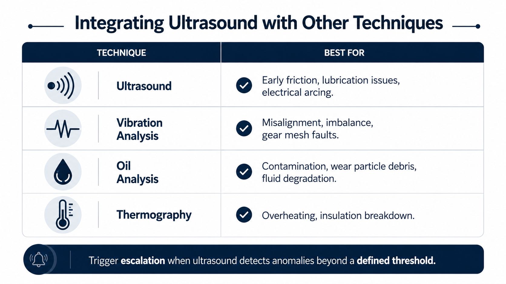
If ultrasound shows roughly a +16 dB rise and vibration is still normal, oil analysis is a smart next step because it can help check for wear debris or fluid degradation. If ultrasound and vibration both point toward damage, thermography can help show how far the thermal effect has spread. If ultrasound says lubrication is off but the oil picture still looks healthy, the problem may be the application method, the grease compatibility, or the way the bearing is being loaded.
A food-and-beverage plant avoided a false-positive bearing replacement by taking that route. Ultrasound suggested friction growth, but the rest of the evidence did not support immediate teardown, so the team checked the oil condition and revisited the lubrication method instead of opening the machine too early. That kind of integration prevents unnecessary work and keeps labor focused on assets that need intervention.
Where each method sits in the stack
Ultrasound should sit at the decision point for friction and lubrication state. Vibration should sit where defect patterns, imbalance, misalignment, or looseness need more characterization. Oil analysis should sit where contamination and wear particles matter. Thermography becomes valuable once heat progression needs to be confirmed.
The mistake is treating one diagnostic as the whole truth. The better move is to let each method answer the part of the question it can actually see.
For teams running variable-speed equipment, a resource on predictive maintenance for VFDs is useful context because the operating profile itself can shift the condition signal. On these assets, the maintenance decision should follow the evidence chain, not the loudest reading.
Common Failure Modes and Maintenance Actions
The field value of ultrasound comes down to one question. What should the crew do next? A rising reading with no action plan just creates anxiety. A reading tied to a maintenance response turns data into uptime.
What the common signatures usually mean
Insufficient lubrication usually shows up as a broadband dB rise that drops after greasing when the film really was the issue. Over-lubrication is trickier, because the dB rise may persist or even increase after greasing as the bearing churns through excess grease. Mounting defects often show directional variations around the housing, which is a clue that the fit or alignment may be wrong rather than the rolling elements themselves. Progressive surface fatigue tends to show repetitive impact signatures at fault frequencies as the defect matures bearing failure reference.
A power generation facility used trending to catch a gearbox bearing defect 14 weeks before predicted failure, which gave the team enough time to replace it during a scheduled outage. That's the true advantage of disciplined ultrasound routes. They buy planning time before the machine turns the problem into an emergency.
Action rules that keep crews out of trouble
- Relubricate immediately: when the dB rise aligns with a lubrication deficit and the reading settles after a controlled grease addition.
- Hold replacement for the next shutdown: when the bearing is trending upward but the signature is still stable enough to manage.
- Escalate to root cause analysis: when the reading stays high after lubrication, the housing shows directional differences, or the defect pattern keeps building.
For a multi-shift plant, the hardest false positive usually comes from over-lubrication. That's why the route tech should always recheck after a delay instead of treating the immediate post-grease reading as final. A bearing that is overfilled can sound worse before it sounds better, and the planner shouldn't order a teardown until the trend and operating context support it.
Next Steps for Your Reliability Program
A strong ultrasonic program doesn't start with more readings. It starts with better decisions about which bearings deserve close attention, which route points are repeatable, and which alarms trigger work. The biggest wins come from consistent baselines, standardized geometry, trend-based interpretation, and integration with vibration, oil analysis, and thermography.
Plants rarely have the time to scan every bearing on every route with the same frequency. That's why asset criticality matters. Use FMEA and criticality ranking to focus the program on pumps, motors, gearboxes, and other rotating assets whose failure would hurt production, quality, or safety the most. For variable-speed equipment, the route logic should also account for changing operating states, which is where an applied resource such as predictive maintenance for VFDs can add useful context.
Ultrasonic testing is a decision-support tool, not a standalone verdict. The highest return comes when maintenance teams use it to trigger the right next action, not just to collect another reading. Forge Reliability offers a free reliability assessment for plants that want to tighten their ultrasound routes, align them with broader condition monitoring, and build a more defensible maintenance plan. Visit Forge Reliability to start that conversation and see how a disciplined program can support fewer surprises and better uptime.