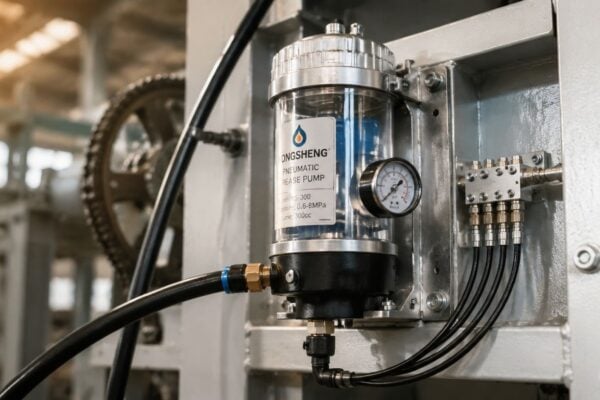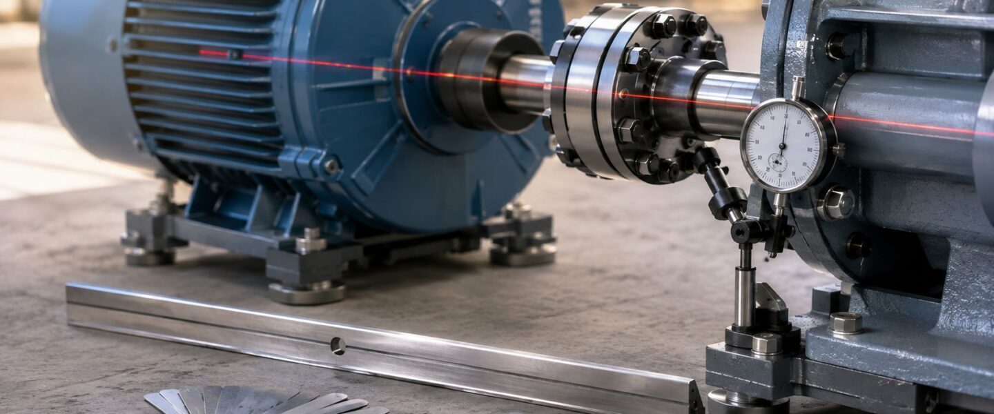
A pump can pass a quick alignment check, run for a shift, and still chew through bearings a few months later. That's the frustrating part of shaft alignment methods in the field, the reading looks clean, but the machine is still living in the wrong condition. On a hot process pump, a gearbox on a conveyor, or a vertical inline pump under load, the question isn't whether the shafts looked straight in the shop, it's whether the machine was aligned for how it runs.
Maintenance teams that keep seeing the same failure pattern often need a better decision process, not just a better tool. The right method depends on the machine, the coupling, the operating temperature, and the kind of error the team is trying to remove. That's why a disciplined approach pairs measurement with root cause thinking, not unlike the logic used in root cause failure analysis.
For manufacturers trying to keep uptime stable, alignment also has to fit into the broader data picture. If the maintenance schedule, asset history, and shutdown planning don't stay synchronized, even a good correction gets lost in the noise, which is why a manufacturing IT uptime guide can be useful background for leaders who manage both production and maintenance systems.
Table of Contents
- When Alignment Keeps Failing on the Same Machine
- Defining Misalignment and Tolerance Before You Pick a Method
- Comparing the Classic Mechanical Methods
- How Laser and Optical Systems Work in the Field
- Soft Foot and Shimming as a Pre-Alignment Discipline
- Why Perfect Alignment Is Not Always the Right Target
- Putting It Together in a Reliability Program
When Alignment Keeps Failing on the Same Machine
A hot process pump keeps coming back with bearing distress. The team aligns it cold, signs off the job, and gets the same call again when vibration rises and the discharge seal starts complaining. That pattern usually means the machine wasn't misaligned in just one way, it was misread in one state and operated in another.
The same thing happens on a gearbox driving a conveyor. Coupling bolts look fine after an outage, then start shearing when the line loads shift with the season. In those cases, the alignment reading is only one clue, because foundation movement, soft foot, thermal growth, or pipe strain can drag the machine back out of tolerance after startup.
The hard lesson is that alignment symptom and alignment cause are not the same thing. A bearing failure can point to offset, angle, mounting distortion, or a correction that looked good on the indicator but never addressed machine condition. That's why a maintenance team needs a common language for what failed, what was measured, and what state the machine was in when it was measured.
Practical rule: if the same coupled machine keeps failing after repeated alignment work, the next step is not “align it again,” it's to ask what changed between the cold reading and the operating condition.
For a plant trying to stabilize uptime, that discipline belongs in the same conversation as production planning and data visibility. The machine work on the floor and the information flow behind it need to support each other, or the same repair cycle repeats.
Defining Misalignment and Tolerance Before You Pick a Method
Misalignment is usually one of two geometric errors. Angular misalignment means the shafts point at different angles, so the coupling faces are not parallel. Parallel misalignment means the shafts stay parallel but their centerlines are offset, like two train tracks that never meet.
A simple car-wheel analogy helps. If the wheel points slightly inward or outward, that's an angle problem. If the wheel sits too far left or right, that's an offset problem. A coupled machine behaves the same way, except the coupling and bearings absorb the error until the load shows up as heat, vibration, seal wear, or early bearing damage.
Static alignment and dynamic alignment
Static, or cold, alignment is measured with the machine stopped and at ambient temperature. Dynamic, or operating, alignment is what the machine experiences after it heats up, loads, settles, and sometimes shifts on its base. On hot pumps and other thermally active machines, cold zero can be a poor target if the machine grows into another position once it's running.
Alignment tolerance is not one fixed number for every machine. It depends on coupling speed, RPM, and the distance between coupling centers, which is why the same correction that works on one machine can be too loose or too tight on another. The commonly repeated 2-mil rule is best treated as a starting point for thinking, not a universal law.
The target is not “zero on paper.” The target is the condition where the machine runs within acceptable load, vibration, and wear limits after startup.
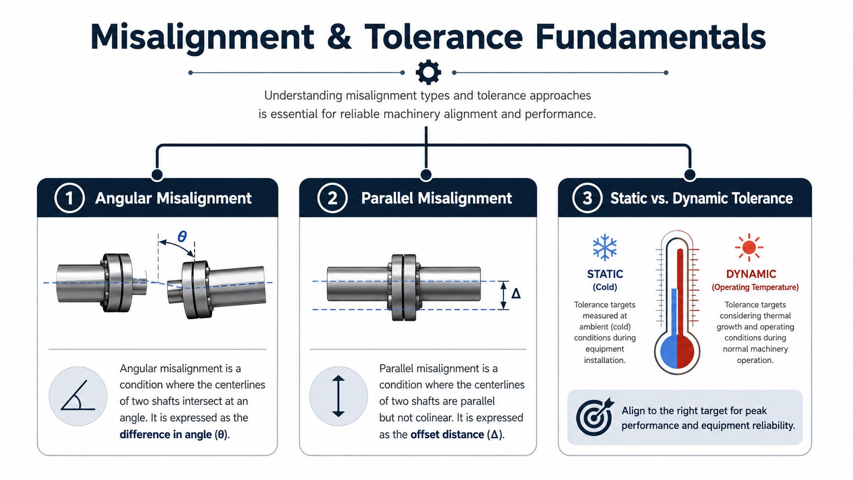
Before choosing any tool, a technician should know three things. First, whether the problem is angular, parallel, or both. Second, whether the machine's operating state changes the target. Third, whether the mounting system is stable enough to hold the correction.
A useful internal reference on that geometry is misalignment of shaft, because the terminology matters before any measurement method does. If the team can't describe the error clearly, the correction usually gets vague too.
Comparing the Classic Mechanical Methods
A pump comes off the base, the motor is shifted, and the first question on the job is usually the oldest one in the trade. Which mechanical method is good enough for this machine, this coupling, and this operating state? The classic family includes the straightedge and feeler gauge, the dial-indicator rim-and-face method, and the reverse-indicator method. The engineering standard for flexible-coupled two-bearing shafts makes clear that the chosen method has to support accurate measurement, analysis, and correction, not just coupling spacing, and it ties alignment quality to machine mounting and case relocation as well ASA S2.75 Part 1-1.pdf).
Straightedge and feeler work for rough setup, not final precision. On a simple machine with an easy target, they can get a pump close enough for a better method to finish the job. On a hot pump, a flexible coupling, or a machine that changes shape under load, they can also create false confidence because the cold position may not be the running position.
Dial indicators give more detail, but they demand discipline and a stable setup. The rim-and-face arrangement can work well in skilled hands, yet it is vulnerable to indicator sag, runout, and face-bar deflection, which can make two readings disagree even when the machine has not shifted. Reverse-indicator methods reduce some of those errors by measuring both shafts, but they still depend on rigid brackets, careful rotation, and an operator who understands what the pattern means in the field.
Mechanical alignment still starts with machine condition, not the tool. If the base is weak, the feet are soft, or the machine moves as bolts are tightened, a precise reading can still point to a correction the machine will not hold. For that reason, a good mechanic treats these methods as measurement devices, not as proof that the machine is healthy. A practical review of precision shaft alignment for induction motors makes the same point in a more electrical setting, alignment quality depends on the machine's actual condition, not just the reading on the indicator.
Mechanical Alignment Methods at a Glance
| Method | Typical Tooling | Field Accuracy | Skill Required | Best Fit For |
|---|---|---|---|---|
| Straightedge and feeler gauge | Straightedge, feeler gauges | Rough setup only | Low | Pre-alignment, simple equipment, quick checks |
| Rim-and-face dial indicator | Dial indicators, rigid brackets | Moderate, but sensitive to setup errors | High | Skilled technicians on accessible machines |
| Reverse-indicator | Dual dial indicators or equivalent setup | Better repeatability than rim-and-face when set well | High | Larger machines, precision mechanical alignment |
| Laser-optic | Laser emitter, sensor, brackets, software | High, if the machine condition is sound | Moderate | Critical assets, frequent alignments, repeat work |
The plain recommendation is this. Mechanical methods still make sense when the machine is simple, the budget is tight, or the crew is trained and working on low-risk assets. They stop making sense when the job keeps repeating, the machine is hard to access, or the plant is paying in downtime for every extra setup minute.
For a maintenance manager, the red flag is not using a mechanical method. The red flag is using one because the program never invested in better diagnosis.
How Laser and Optical Systems Work in the Field
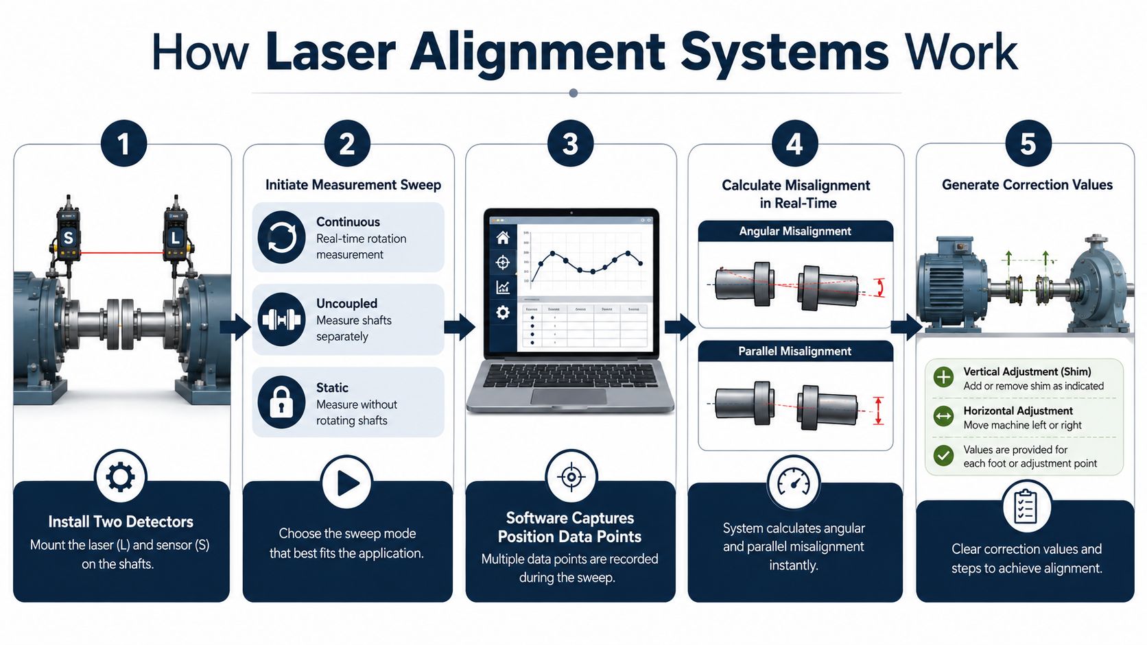
A laser alignment job starts with a transmitter on one shaft and a sensor on the other. As the shafts rotate, the system tracks how the beam moves across the detector, then turns that movement into offset and angular correction values. That geometry matters more than the brochure language, because the reading still depends on bracket stiffness, shaft setup, and the quality of the data gathered during the sweep. Field guidance also points to sensor accuracy of about ±0.001 in. or better for reliable correction work, as covered in the RS training material.
The practical advantage is speed and repeatability. Laser systems are usually faster to execute than dial indicators, they reduce the amount of setup skill needed to get a clean result, and they can deliver the same precision again and again when the machine condition is stable. That is why many plants use them on critical equipment. They still do not fix a bad base or soft foot. They mainly reduce the operator error that often hides the underlying problem.
Sweep modes and what the software is really doing
Three workflows show up often in the field, continuous sweep, uncoupled sweep, and static measurement. Continuous sweep captures many points during a single rotation. Uncoupled sweep works when the machine cannot stay fully coupled in the normal arrangement. Static measurement fits some constrained setups, but it does not give the same depth as a multi-point sweep.
The software calculates the movement path of the beam across the sensor, then solves for the correction values that should bring the shafts into tolerance. That only works when the brackets stay stiff and the machine does not shift under them. It also depends on the machine condition staying consistent from the first reading to the last. A hot pump, a flexible coupling, or a frame that moves as bolts are tightened can make a cold-alignment number look better than the actual running condition.
Field reality: a laser system will not rescue a machine with soft foot, loose hold-downs, or bracket flex. It will usually expose them faster.
A motor-pump skid on a chemical processing line shows the difference. A dial-indicator setup may take multiple installs and rechecks to satisfy both angular and offset readings, while a laser system can often capture the data in one setup and guide shim and move corrections directly. The speed gain matters most on machines that have to be aligned, verified, and returned to service in the same outage window. The same logic applies when a plant uses mechanical engineering for manufacturing readiness support to keep installation work tied to the actual operating condition instead of a clean number on a screen.
A practical reference on this method family is precision shaft alignment for induction motors, because the strongest laser setup still depends on sound machine condition and disciplined correction.
Soft Foot and Shimming as a Pre-Alignment Discipline
Soft foot is one of the easiest alignment problems to miss and one of the most expensive to ignore. It happens when one machine foot doesn't sit flat on the base, so tightening the bolts bends the frame instead of clamping the machine. The result is a moving target, because the machine changes shape as the hold-downs are tightened.
There are four patterns to watch for. Parallel soft foot shows up when one foot is not supported. Angular soft foot appears when the foot contacts at an angle. Jack-bolt soft foot comes from excessive jacking force during adjustment. Combination soft foot is a mix, which is common on older skids and after repeated rework.
What the technician should check first
- Loose and uneven bolt response: tighten the hold-downs in sequence and watch for a foot that changes position differently from the others.
- Visible gaps under a foot: slide appropriate feelers under the base to find unsupported contact.
- Shim condition: replace bent, rusted, or contaminated shims instead of stacking around them.
- Frame movement during tightening: if the reading moves when the bolt is torqued, the base is altering the machine.
Shim discipline matters because sloppy stacks can undo a clean alignment job. A pile of mixed shims, burrs, or oil-contaminated layers compresses differently under load and can introduce a new error right after startup. The fix is simple in principle, but it takes patience on the floor, clean shims, a flat base, and a final check after the bolts are set.
A useful practical resource for floor-ready execution is one-point lesson example, especially for crews that need a short, repeatable alignment standard at the machine.
Good practice: correct soft foot before chasing coupling numbers. Otherwise, the machine is aligned against a moving base.
A reliability engineering partner can also help with the kind of mechanical detail that makes these jobs repeatable. A mechanical engineering for manufacturing readiness resource may be useful where mounting design, hold-down behavior, and base flatness keep undermining otherwise good field work.
Why Perfect Alignment Is Not Always the Right Target
A cold alignment that looks perfect on the ledger can miss the mark once the machine heats up and settles into service. Hot pumps, vertical inline pumps, and coupled machines with different thermal paths often move into a different running position than the one you measured at shutdown. The target has to reflect operating condition, not just a shutdown reading.
I have seen this most clearly on vertical inline pumps. The motor and pump assembly can grow after startup, so the cold centerline sometimes has to be set with a deliberate offset that brings the shafts into line at normal temperature. That is not guesswork. It is a correction for the movement the machine will make in service, not a chase for zero at ambient conditions.
Dynamic alignment changes the question
Dynamic alignment focuses on position over time, not a single point reading. Engineering guidance on shaft alignment condition monitoring and workflows points toward targets that account for motion, operating state, and recurring duty cycles shaft alignment condition monitoring and workflows. That approach fits machines that move after startup and do not hold the same geometry through the whole run.
Laser workflows support that way of working because they can capture multi-point datasets through continuous sweep and related methods. They do not replace judgment at the machine. They give the crew a clearer view of how the unit behaves across the measurement window, which helps when thermal growth and foundation movement shift the running position.
If a machine always fails hot, the target has to reflect hot behavior.
Many maintenance programs still treat alignment like a one-time corrective task rather than an ongoing reliability practice. The better target is tied to the machine's operating envelope, the coupling's flexibility, and the system's tendency to move under load. On a pump that runs hot and stable, the cold correction may need to look wrong at shutdown so it runs right in service.
For teams building a broader reliability routine, a reliability program roadmap can help organize how alignment, monitoring, and follow-up checks fit together in one process.
Putting It Together in a Reliability Program
The strongest alignment program doesn't rely on one method. It uses the right method for the machine, checks route-based targets on critical assets, and escalates when failures keep recurring after a clean correction. That's the point where a program stops being a maintenance task list and becomes a reliability process.
A practical program usually looks at recurring coupling failures, premature bearing wear, and post-overhaul vibration spikes as alignment clues first, then checks soft foot, base condition, thermal growth, and the measurement method before blaming the coupling. For teams that want a broader roadmap for building that discipline, this reliability program roadmap is a good reference point for organizing the work.
Forge Reliability also provides precision shaft alignment as part of its reliability service set, which can help when plants need structured execution on pumps, motors, and gear-driven assets instead of another one-off repair. The useful decision is simple, if the site has stable procedures and trained staff, insource the work. If the same machines keep coming back, bring in a reliability team that can connect measurement, condition monitoring, and root cause thinking.
The next step for a plant that recognizes the symptoms is a free reliability assessment. It gives maintenance and operations a structured way to sort out whether the problem is the method, the machine condition, or the operating target, and it turns recurring alignment pain into a plan the team can follow.
Forge Reliability helps plants separate a true alignment problem from soft foot, thermal growth, and base issues that keep bringing machines back out of service. If recurring bearing wear, coupling failures, or hot-running pumps are showing up in your plant, visit Forge Reliability to request a free reliability assessment and get a practical plan for the machines causing the most downtime.