The pump discharge gauge looks steady during production, but the regulator chatters when demand drops. Maintenance has adjusted the spring, operations wants another set-point change, and nobody has confirmed whether the relief path can handle a blocked outlet. That's a pressure-system problem, not necessarily a bad regulator.
The useful diagnosis starts with synchronized pressure and load measurements, then separates control faults from protection gaps. A healthy upstream reading can conceal inadequate relief capacity, restricted discharge piping, or a regulator operating outside its usable flow range.
Table of Contents
- What Regulator Back Pressure Means in Practice
- How the Regulator Holds Upstream Pressure
- Monitoring Trends That Reveal Regulator Health
- Symptoms, Likely Causes and First Checks
- Sizing and Sensing Rules That Prevent Hunting
- Overpressure Protection Beyond the Regulator
- Field Fixes for Piping, Sensing and Valve Design
- Start a Regulator Test Routine With a Free Assessment
What Regulator Back Pressure Means in Practice
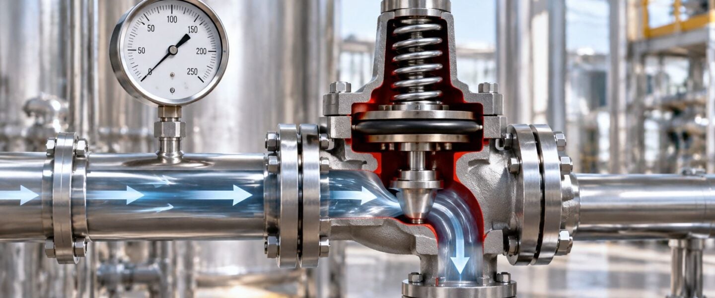
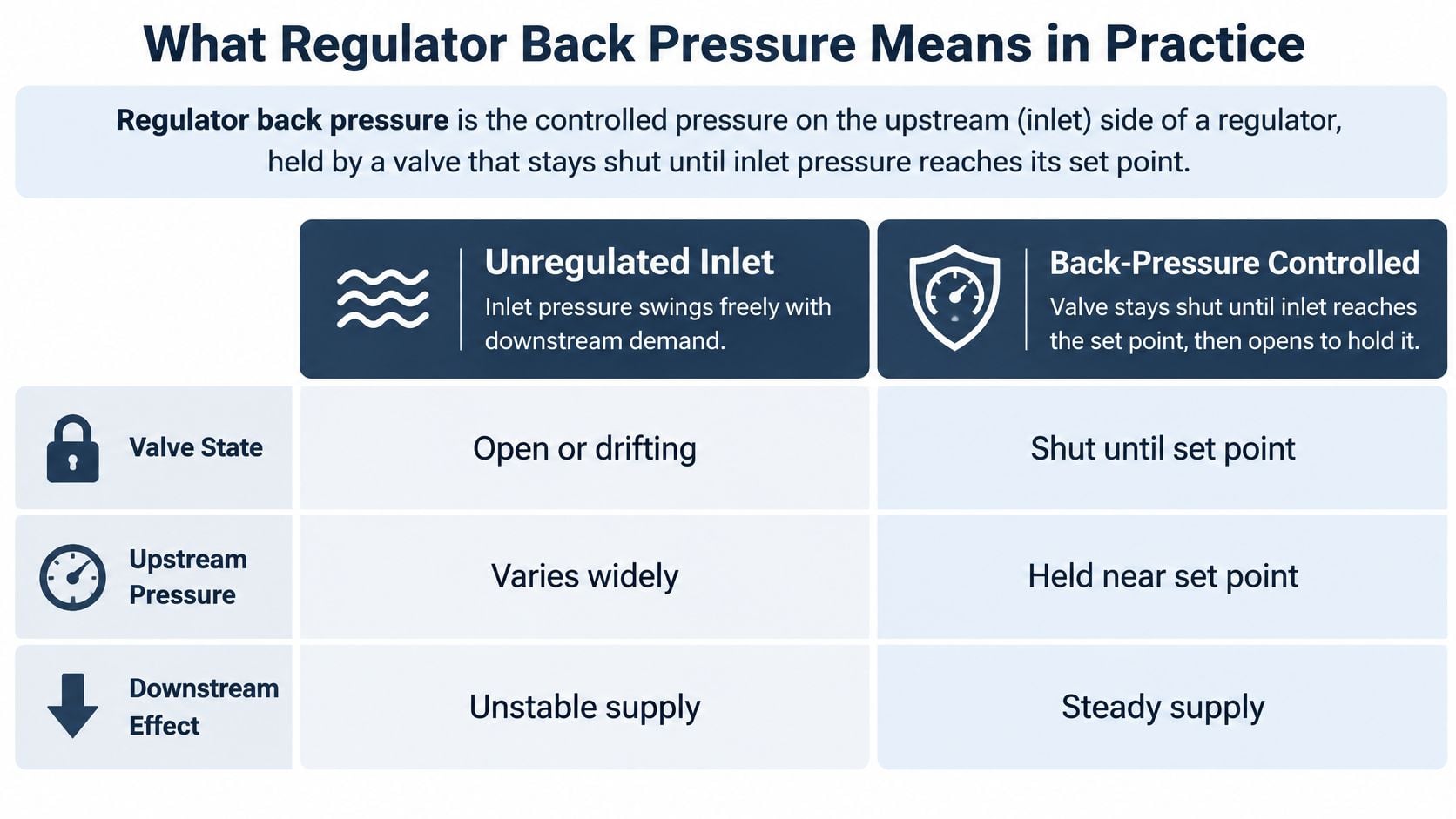
Regulator back pressure is the controlled pressure on the upstream, or inlet, side of a regulator, held by a valve that stays shut until inlet pressure reaches its set point. A weighted valve on a pressure cooker provides a useful analogy: nothing vents until internal pressure overcomes the closing force.
A pressure-reducing regulator does the opposite job. It throttles incoming supply to maintain outlet pressure, much like a tap limiting what downstream fixtures receive. Neither device should automatically be treated as independent overpressure protection.
Back-pressure versus pressure-reducing regulator
| Feature | Pressure-reducing regulator | Back-pressure regulator |
|---|---|---|
| Pressure it controls | Downstream (outlet) pressure | Upstream (inlet) pressure |
| Sensing point | Outlet line | Inlet line or the protected vessel |
| Valve state at rest | Open, throttling as outlet pressure rises | Closed until inlet reaches the set point |
| Typical use | Reducing supply to a tool, burner or instrument | Pump discharge control, filter differential, vessel protection |
The rest positions describe conventional self-operated arrangements, not every available regulator design. The important distinction is which pressure the device senses and controls.
Match the duty, not the connection
The industrial operating envelope is broad: commercial back-pressure regulators are available for set points from approximately 5 to 300 psig (0.34 to 20.7 barg), while specialized high-pressure designs reach 10,000 psig (690 barg), within the applications summarized by the industrial back-pressure regulator documentation. Here, psig and barg mean pressure measured relative to atmospheric pressure.
Typical duties include holding pump discharge pressure, preserving minimum pressure differential across filters, controlling vessel pressure, and stabilizing analyzer or chemical-feed systems. Differential pressure means the difference between inlet and outlet pressures. Maintaining it across a filter requires consideration of pressure on both sides, not just installation of a regulator.
In vessel service, a back-pressure regulator can discharge routine excess flow to keep operating pressure controlled. That operating function doesn't establish emergency relieving capacity.
Selection rule: A matching pipe connection establishes mechanical fit, not control suitability.
Selection must account for upstream pressure, gas or liquid service, temperature, and the complete flow range. A replacement with the same connection size can still have unsuitable internal capacity, diaphragm materials, or spring characteristics.
How the Regulator Holds Upstream Pressure
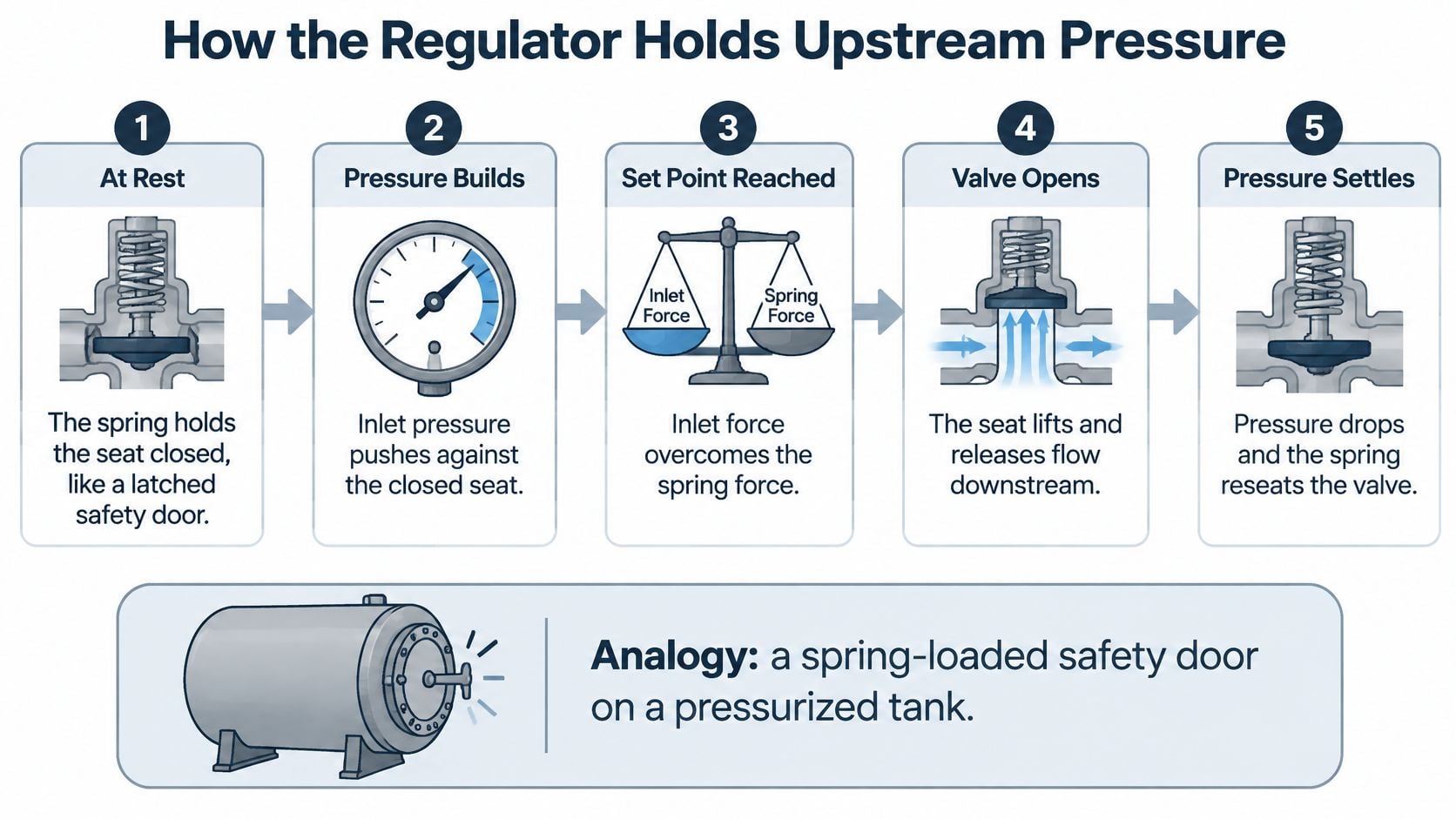
A spring-loaded back-pressure regulator holds pressure through a force balance. Upstream pressure pushes the valve open and the spring pushes it closed, and the seat settles wherever those forces equalize. When the set point drifts, one side of that balance has changed, and the mechanism itself points to where to look.
Follow the force through the mechanism
At rest, the seat is closed. The spring applies the closing load through the operating assembly. The technician's question is whether the seat can seal and whether the installed spring belongs in that regulator.
Upstream pressure acts beneath the diaphragm. The diaphragm is a flexible pressure-sensing element that converts pressure into force. The useful question is whether it sees true process pressure or a delayed signal through a restricted sensing passage.
The opening force overcomes the spring force. The valve opens sufficiently to discharge flow into the outlet or approved vent system. The technician must establish whether that discharge path can in fact accept the flow.
Falling upstream pressure allows the spring to close the seat. During steady operation, the regulator normally modulates rather than repeatedly slamming fully open and shut. Repeated abrupt movement calls for investigation, not another adjustment.
On a chemical-feed skid, pressure remaining above set point doesn't prove the feed pump has failed. A restricted return line, wrong spring, contaminated seat, or damaged trim, the internal parts that meter and shut off flow, can produce the same complaint. The same caution runs the other direction: a gauge holding steady at set point says nothing about whether the relief path downstream can pass the full flow. Controlled pressure is evidence that the force balance is working, and that is all it is evidence of.
Separate pressure rating from adjustment range
A regulator's maximum allowable inlet pressure and its adjustable control range are different limits. The medium-pressure regulator document lists a maximum inlet pressure of 16 bar (300 psi) and a spring-loaded control range up to 5 bar (70 psi).
A body rated for that maximum inlet pressure still needs a spring whose adjustment span covers the intended set point. A spring set to the desired pressure still needs a body, diaphragm and trim that can withstand the system's design pressure. The two limits get checked separately, because satisfying one says nothing about the other.
Before changing a set point, maintenance should verify:
- Actual pressures: Confirm upstream and outlet readings with calibrated instruments.
- Operating conditions: Establish temperature, fluid condition, and flow range.
- Protection capacity: Confirm that the independent relief arrangement remains suitable.
Turning the adjustment screw before those checks can conceal the original fault and consume the intended margin between operating control and relief activation.
Monitoring Trends That Reveal Regulator Health
A single gauge reading shows a condition at one moment. A synchronized trend shows whether the regulator responds properly as the process changes. Maintenance needs the pressure relationship, valve movement, and operating load on the same time base.
Regulator trend parameters and reading patterns
| Parameter | Sampling need | Healthy pattern | Warning pattern |
|---|---|---|---|
| Upstream pressure | Seconds during tests; routine trend for daily health | Holds within the set band | Repeated overshoot or saw-tooth shape |
| Downstream pressure | Same interval as upstream | Stable and consistent with demand | Rising deviation as the outlet restricts |
| Valve position | Fast enough to capture each reversal | Smooth travel with few reversals | Rapid reversals or travel pinned near closed at low demand |
| Flow or pump and compressor load | Time-stamped with pressure | Pressure tracks load predictably | Pressure swings without a load change |
| Cycling frequency | Counted per shift or per day | Low and steady | Rising after maintenance or a seasonal load change |
The sampling entries are practical collection instructions, not universal acceptance limits. A targeted recording must capture the actual cycling; a historian that stores only averaged values can hide abrupt reversals.
Collect signals in a useful order
Start with upstream pressure at the intended control point, then add downstream pressure at the regulator outlet. Measuring only upstream pressure leaves maintenance unable to distinguish a control problem from increasing discharge resistance.
Next, record valve position where instrumentation permits. A self-operated regulator may not provide an electronic position signal, so safe nonintrusive observation or temporary instrumentation may be necessary. Guards and pressure boundaries must remain intact during operation.
Finally, align flow or machine load with the pressure signals. A properly configured condition monitoring system should preserve timestamps and operating context, rather than merely store unrelated measurements.
Compare behavior at minimum, normal, and peak demand. A valve can control acceptably during production yet reverse rapidly near closure when the plant idles. Testing only the comfortable operating point misses that failure mode.
Interpret movement, not just averages
A modest, repeatable pressure change following a load transition differs from a pressure oscillation that appears while load remains steady. The latter directs attention toward sensing, valve movement, or control interaction.
Pressure trending should be supported by a usable maintenance record:
- Set-point history: Record who changed the setting and the reason.
- Event context: Retain alarms, equipment starts, and demand changes.
- Measurement confidence: Identify calibrated reference gauges and instrument locations.
- Mechanical condition: Record the last trim inspection and its findings.
An unchanged average pressure doesn't mean an unchanged regulator. Faster cycling can increase wear while the daily average stays comfortable.
When cycling increases after maintenance or a seasonal load change, the team should log a reliability event. Restoring the old setting without documenting the new behavior loses evidence needed to distinguish installation changes from mechanical deterioration.
Symptoms, Likely Causes and First Checks
Troubleshooting should begin with the pressure and valve trends, not the assumption that the valve body needs replacement. The table provides a first filter; each likely cause still requires confirmation against the actual process arrangement.
Regulator symptoms, likely causes and first checks
| Symptom | Likely cause | First check |
|---|---|---|
| Repeating saw-tooth pressure with fast valve reversals | Oversized valve, sensing lag or insufficient damping | Trend valve position against pressure at minimum and peak flow |
| Rapid open-close chatter and seat wear | Oversized valve, excessive pressure drop or worn piston guiding | Compare behavior at minimum and peak demand; inspect guiding surfaces |
| Upstream pressure stays above set point | Restricted discharge, wrong spring or damaged trim | Check outlet line, spring range and trim condition |
| Slow, late or drifting response | Blocked or long sensing line, condensate or scale | Inspect sensing line for blockage and confirm a direct, low-volume tap |
| Valve fully open yet pressure falls short at peak demand | Undersized valve or high outlet back pressure | Compare Kv or Cv with peak flow; measure outlet pressure |
| Seat leakage after repeated cycling | Chatter damage to the seat | Inspect seat and replace damaged trim before returning to service |
The fully open symptom requires particular care. If “falls short” means insufficient discharge capacity, valve sizing and outlet pressure are appropriate checks; if upstream pressure is below target, the team must also investigate inadequate supply or excessive process withdrawal. An undersized back-pressure regulator more commonly leaves upstream pressure too high when it cannot discharge enough flow.
Distinguish chatter from ordinary modulation
Chatter is rapid, repeated opening and closing. Hunting is continuing oscillation around the intended operating condition, often involving the sensing and flow response as well as the valve.
The regulator troubleshooting manual associates chatter with oversizing, inadequate rangeability, excessive pressure drop, and worn piston-and-cylinder guiding surfaces. Rangeability describes the usable span between low and high controllable flow.
Worn guidance matters because instability isn't always a selection mistake. A regulator that previously handled the operating range can develop erratic travel as its moving parts lose proper support.
A food-processing steam-header example
Consider a steam-header regulator selected for maximum production flow. During sanitation or idle periods, the required discharge flow falls, leaving the valve working close to its seat. Small movements then produce disproportionate flow changes, followed by pressure oscillation and repeated reseating.
The result can include unreliable heating and accelerated seat wear. Increasing spring load may temporarily alter the symptom without correcting the low-flow mismatch.
Smaller trim may improve low-demand control, but only if it still passes peak flow. A parallel arrangement can separate low- and high-flow duties, while damaged guidance requires mechanical repair rather than a sizing calculation alone.
Similar discipline applies when investigating compressor pressure loss: measured pressure relationships should determine whether maintenance addresses piping, control, or machinery. Before any set-point adjustment, the work order should include the symptom's timestamp, operating load, and valve behavior.
Sizing and Sensing Rules That Prevent Hunting
Pipe diameter is the wrong starting input for regulator sizing. The useful starting conditions are maximum required operating flow and the smallest available pressure differential across the regulator. Both belong to the system around the valve: required flow follows the process, and available differential depends on what sits downstream at each operating case.
Establish capacity and controllability together
The required Kv is a metric flow coefficient describing valve capacity under defined reference conditions. Kvs is the rated coefficient at full opening, while Cv expresses capacity under a different unit convention and isn't numerically interchangeable with Kv.
The back-pressure regulator sizing guidance recommends calculating Kv from maximum operating data and minimum differential pressure, then selecting Kvs approximately 30% above the calculated Kv with additional allowance for high-viscosity liquids and fluids that vaporize during pressure reduction, and its application ratings span hardware as different as a high-pressure regulator rated for 3.5 US gal/min at up to 3,000 psi and 500 cP viscosity and an instrument regulator offering flow coefficients of 0.06, 0.1, and 0.3.
Viscosity, a fluid's resistance to flow, raises the pressure drop needed to pass a given throughput, so a coefficient derived from water underpredicts the capacity a viscous service requires. Flashing occurs when liquid vaporizes as pressure falls across the valve, and the resulting two-phase flow behaves differently from the liquid the calculation assumed.
Undersizing creates excessive velocity and pressure loss, limiting discharge at peak demand. Oversizing does the opposite damage: ordinary operation sits near the seat, where small plug movements produce large changes in flow and the valve cycles between barely open and closed.
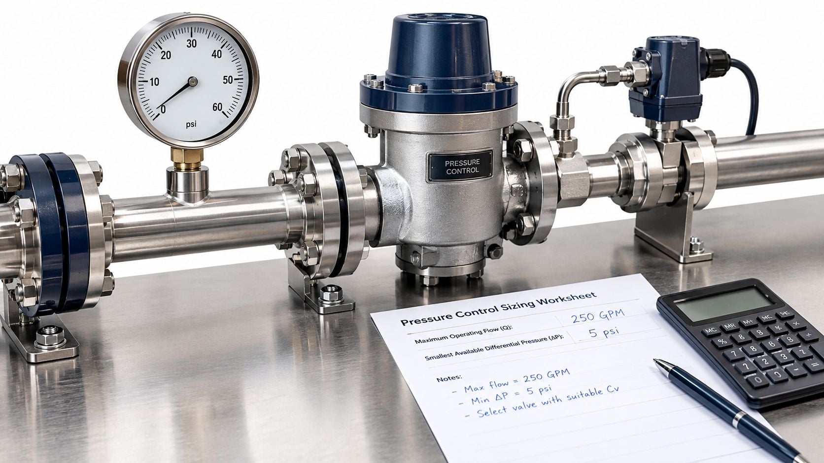
A capacity calculation should therefore be paired with a low-flow check. Extra capacity earns its margin only while the regulator can still modulate smoothly through normal turndown.
Give the regulator a representative pressure signal
The sensing connection should be direct and low-volume at the intended control point, consistent with the installation principles in the industrial back-pressure regulator guide. A long or restrictive line delays the signal: process pressure moves, the regulator responds late, then overcorrects.
Outlet pressure deserves the same scrutiny as inlet pressure. As outlet back pressure rises, the available differential across the valve falls, so a regulator sized against an unrealistically low outlet pressure can lack capacity in service even though the arithmetic looked correct on the worksheet.
The pressure-rating review must cover the body, diaphragm assembly, spring housing, and trim against their applicable design limits. Normal set point alone isn't an adequate specification for the complete assembly.
In a pump bypass loop, the regulator continuously adjusts recirculation flow as the process takes more or less delivery. An oversized bypass valve repeatedly over-discharges and closes, sending pressure fluctuations back into the header the loop was meant to protect. Effective correction combines a capacity range matched to actual demand, representative sensing, and a return path that stays available throughout operation.
Sizing and sensing settle control stability, nothing more. A regulator that holds a steady upstream gauge through every observed case has proven it can handle that duty; the loads the valve never sees in normal service belong to a different check.
Overpressure Protection Beyond the Regulator
A regulator can make the gauge look calm while leaving the dominant overpressure scenario unchanged. Stable control proves only that the regulator can handle the conditions present during observation. It doesn't prove emergency capacity, safe discharge routing, or independence from a common failure.
The pressure-regulator selection guide recommends suitable overpressure relief in parallel with a back-pressure regulator where equipment protection is required. The relief device must be selected for its protective duty, not treated as another process-control valve.
Separate the protective functions
- Normal pressure control: The regulator modulates routine discharge flow.
- Abnormal pressure protection: An independent relief device passes the credible overpressure load.
- Emergency shutdown: An interlock detects a dangerous condition and initiates the specified safe response.
An interlock is a control function that automatically initiates or prevents an action when defined conditions occur. Its presence doesn't eliminate the need to assess relief requirements.
The hazard review should examine blocked outlets, gas breakthrough into liquid systems, thermal expansion of trapped liquid, pump runout, pilot or actuator failure, and loss of usable differential pressure. Pump runout means operation toward the high-flow end of the pump's available performance curve.
For each applicable case, engineering must establish whether the relief path can pass the credible load with the regulator failed closed. Settings must respect every component exposed to the relieving pressure, including the protected vessel and connected equipment.
Check the complete relief path
OSHA's oxygen-fuel-gas welding and cutting requirements illustrate the relationship: service-piping relief settings must not exceed system design pressure, specified back-pressure protection must respect the lower applicable protection-device rating, and relief vents must be at least as large as their inlets without moisture-trapping low points. Those requirements have a defined regulatory scope; they aren't a substitute for the code governing another process.
For an ammonia refrigeration receiver, the team must verify the applicable refrigeration requirements, certified relieving capacity, and discharge destination. Liquid accumulation, a closed isolation valve, or excessive discharge resistance can undermine an otherwise suitable relief device.
Protection test: The review must explain what happens when the regulator cannot open, not merely demonstrate that it opens during production.
Maintenance records should retain approved set pressures, discharge-path verification, controlled isolation-valve positions, and proof-test results. A steam relief valve review likewise needs to include the surrounding piping, not just the spring setting.
For facilities managing major process hazards, Safety Space's explanation of the 14 elements of PSM provides useful context for connecting mechanical integrity, operating procedures, and management of change.
Field Fixes for Piping, Sensing and Valve Design
Installation and sensing defects deserve attention before replacement hardware. They can often be corrected without changing the control concept. Capacity or design changes come after the team establishes what pressure the regulator senses and where its discharge flow goes.
Field fixes by symptom context
| Fix | Fits when | Watch-outs |
|---|---|---|
| Shorten the sensing line and tap near the control point | Hunting from lag in a long or restrictive line | Use service-appropriate drainage pitch and avoid liquid-trapping low points |
| Move the sensing tap into a suitable straight run | Turbulence near elbows, tees or valves | Follow the equipment-specific spacing guidance |
| Install an upstream steam trap with strainer protection | Condensate or scale reaches a steam regulator | Check strainer differential pressure and trap operation |
| Replace with smaller trim or resize the valve | Chatter at low demand from an oversized valve | Verify minimum and peak flow |
| Reduce regulator pressure drop or split duty across valves | Chatter from excessive pressure drop | Recheck capacity and rangeability |
| Use a balanced regulator design | Changing outlet back pressure shifts the set point | Confirm fluid compatibility, range, and pressure class |
| Enlarge or shorten relief inlet piping | Inlet pressure loss exceeds the permitted limit | Check elbows, isolation valves, and fouling |
| Preserve control-to-relief setting margin | Steam control approaches relief activation | Confirm against the current approved relief setting |
Correct the steam installation as an assembly
For the pilot-operated steam arrangement described in the steam back-pressure regulator installation guidance, the regulator belongs horizontally with bypass and isolation valves, an upstream steam trap, and strainer protection; the sensing connection belongs approximately 10 pipe diameters from the nearest fitting and about 1 foot from elbows, tees, valves, or restrictions, with downward drainage pitch, while control is set 2 to 5 psi gauge below the safety-relief setting.
Those are application-specific installation instructions, not universal dimensions for every regulator. Bypass arrangements also require operating controls so personnel can't inadvertently defeat pressure control or protection.
In a paper mill steam header, condensate, scale, or a turbulent sensing tap can make a healthy pilot appear defective. Checking trap discharge, strainer condition, gauge calibration, and sensing-line continuity can prevent unnecessary diaphragm replacement. Properly applied ultrasonic leak detection can support trap and leakage investigations.
Change the design only for an established cause
A balanced regulator reduces the influence of outlet-pressure forces on its operating balance. It can help when varying outlet back pressure shifts control, but it won't clear a blocked return line.
For relief inlet piping, the pressure-relief valve technical manual describes ASME Section VIII guidance recommending no more than 3% pressure drop between the protected vessel and relief valve. Long, restrictive, or fouled inlet arrangements therefore require engineering review rather than a stronger spring.
Every modification must be checked at minimum and peak flow before acceptance.
Start a Regulator Test Routine With a Free Assessment
A critical regulator needs a repeatable test record, not an undocumented adjustment whenever pressure complaints return. Before the next shutdown, the maintenance planner should assign an owner, establish safe test boundaries, and collect the operating evidence needed for an equipment condition assessment.
A practical routine for critical regulators
Pull the current design basis. Assemble upstream and outlet pressures, temperature, fluid condition, flow range, and relief capacity. These establish what the regulator must control and withstand. The common slip is relying on the nameplate while ignoring process changes made since installation.
Trend the full operating range. Record upstream pressure, downstream pressure, valve position where available, and machine load through minimum, normal, and peak demand. This exposes low-flow instability as well as capacity limitations. Testing only during steady production misses both startup and turndown problems.
Verify the approved set point. Compare the present setting with design documentation and the change log, using a calibrated pressure reference. This distinguishes intentional changes from accumulated field adjustments. A convenient panel gauge isn't sufficient evidence if its calibration or sensing connection is uncertain.
Test protection independently. Qualified personnel should function-test the relief device using an approved procedure and verify discharge routing, vent sizing, and liquid-trapping sections. The reason is straightforward: control operation and protective performance are separate duties. A successful opening test alone doesn't establish worst-case relieving capacity.
Inspect the pressure signal and auxiliaries. Check sensing passages, strainers, traps, and gauge calibration before condemning the regulator. A gradually obstructed tap can produce delayed response without an obvious external defect. The common slip is treating an apparently intact sensing tube as a proven pressure connection.
Examine trim, seat, and guidance. After safe isolation, depressurization, and verification of stored-energy removal, inspect for wear, deposits, scoring, and damaged guiding surfaces. Record the findings against the operating symptoms. Replacing trim without retaining inspection evidence makes recurring failures harder to diagnose.
Set the next interval from condition and risk. Use trend history, service severity, inspection findings, and applicable requirements to establish the next test. Review the interval after process changes or abnormal cycling. Leaving the original interval untouched can disconnect the maintenance plan from actual duty.
The final acceptance record should distinguish what was measured, what was inspected, and what was established by engineering calculation. Unverified assumptions should remain open actions rather than become implied approvals.
Forge Reliability offers a free reliability assessment of regulator sizing, sensing, protection arrangements, and trend data at no cost. Visit Forge Reliability to arrange a review, bringing the current design basis, pressure trends, and relief-device records so the first discussion addresses specific failure risks rather than general maintenance advice.