
A centrifugal pump rarely fails without leaving evidence. The problem is that the evidence often sits in a vibration spectrum, a temperature trend, an oil sample, or a changing motor-current pattern while the pump continues to run. By the time operators hear grinding, see seal leakage, or lose discharge pressure, the maintenance window may already be gone.
Predictive maintenance of pumps using condition monitoring turns those weak signals into decisions. The practical challenge isn't choosing the largest possible sensor stack. It's deciding which pumps deserve monitoring, defining what constitutes a meaningful change, and routing each alarm to a person who can confirm the fault and plan the repair.
Table of Contents
- The Hidden Cost of Unplanned Pump Failures
- Five Core Diagnostic Techniques for Pumps
- Designing Your Monitoring Route and Schedule
- Setting Alarm Criteria and Interpreting Data
- Integrating Data Workflows and Maintenance Strategies
- Choosing Between Route-Based and Continuous Monitoring
- Implementing Your Predictive Maintenance Program
The Hidden Cost of Unplanned Pump Failures
A centrifugal pump can turn a routine maintenance task into a production emergency in a single shift. One unplanned failure typically costs $40,000 to $200,000, before accounting for operational disruption and secondary damage. Emergency repairs can cost three to five times more than planned maintenance, making timing a direct business concern. A bearing replacement or seal intervention completed during an outage is controlled work. After a bearing seizure, the same job may involve the pump, coupling, shaft, and lost production. (industrial pump predictive maintenance guidance)
Pump cost also gives a poor indication of plant risk. Pumps may represent about 7% of plant or refinery maintenance costs, yet the failure of one cooling-water, chemical-transfer, or boiler-feed pump can interrupt an entire process path. FMEA criticality ranking should therefore consider production consequence, operating conditions, available spares, and repair lead time, not purchase price alone. (rotating-equipment predictive maintenance research)
Practical rule: Rank a pump by the consequence of losing it, then decide how much monitoring and response capacity it warrants.
Why early warning changes the repair
Vibration-based monitoring can provide roughly two to eight weeks of advance warning before some industrial pump failures. That interval can support planned bearing replacement, seal work, coupling alignment, or impeller inspection instead of an emergency response after shutdown. Use the industrial pump predictive maintenance guidance when establishing the initial monitoring approach.
Early warning becomes useful only after the plant defines what happens next. Each alarm needs an owner, a diagnostic threshold, a confirmation step, and a work-order path. Without those controls, a sensor adds alerts without reducing uncertainty. Route abnormal vibration, rising temperature, changing pressure, reduced flow, and visible leakage to the people who can verify the condition and schedule corrective work.
A centrifugal pump reliability and failure prevention guide can support the initial failure review. Apply its lessons to a plant-specific ranking, then set alarm criteria around credible failure modes and operating context. The objective is a repeatable path from condition change to planned intervention, with fewer false positives and fewer expensive surprises.
Five Core Diagnostic Techniques for Pumps
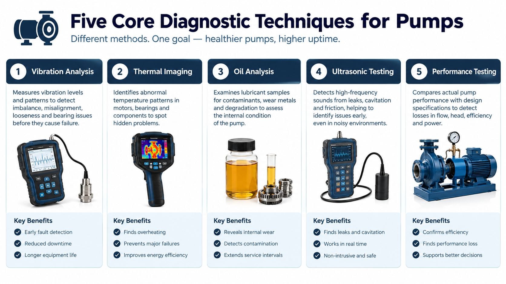
A pump train needs more than one measurement because its failure modes don't share one signature. Misalignment may appear clearly in vibration, while lubricant contamination appears in oil analysis and a process restriction may reveal itself through motor current and hydraulic behavior.
Vibration analysis
Vibration analysis is the primary mechanical diagnostic for most rotating pump trains. Accelerometers measure vibration at bearing housings and motor locations, while frequency analysis separates overall severity from specific components. A spike at 2x running speed is commonly associated with shaft misalignment, a condition that can load bearings and mechanical seals while increasing energy loss. (pump vibration diagnostic guidance)
The analyst should compare horizontal, vertical, and axial readings, then examine the spectrum rather than reacting to overall RMS alone. Bearing defect frequencies, looseness patterns, unbalance, and hydraulic excitation require different corrective actions.
Oil analysis
Oil analysis identifies contamination, wear debris, and water ingress. It can also show lubricant degradation before a bearing reaches a visibly damaged state. For an oil-lubricated pump bearing, the sample becomes a record of internal wear, but only if sampling points, cleanliness, and labeling remain consistent.
Thermography
Infrared thermography detects abnormal heat at bearing housings, motor connections, and pump components. A hot bearing may indicate lubrication trouble, excess load, or developing damage. A hot electrical connection may indicate resistance or imbalance rather than a mechanical pump fault. Thermal evidence narrows the diagnostic path, but it shouldn't be treated as a complete diagnosis by itself.
Ultrasonic testing
Ultrasonic methods detect high-frequency friction and impact signals. They can support early checks for lubrication condition, bearing distress, leaks, and cavitation-related activity, especially where conventional vibration data is difficult to interpret. Operators should account for background noise and establish a baseline under known operating conditions.
Motor Current Signature Analysis
Motor Current Signature Analysis, or MCSA, evaluates changes in motor current associated with electrical faults and pump loading. Because the motor is coupled to the pump, hydraulic problems such as restricted suction, unstable flow, or cavitation can influence the current pattern. A reported pump-fault MCSA platform achieved 91.2% fault-detection accuracy, a 3.8% false-positive rate, and a 95% reduction in post-processing time across 40 operating points, with 0.1 Hz frequency resolution. (pump-fault MCSA study)
These techniques work best as complementary evidence. A practical condition-based maintenance approach uses vibration to identify mechanical change, temperature and ultrasound to support severity assessment, oil analysis to identify internal wear, and current data to connect the pump condition to motor and process behavior.
Designing Your Monitoring Route and Schedule
A monitoring route should begin with the consequence of failure, not with the sensor catalog. An FMEA, or Failure Modes and Effects Analysis, asks how each pump can fail, what causes the failure, how the failure appears, and what happens if the team misses it. A Pareto analysis then shows which failure modes and assets account for the greatest operational exposure.
Rank the assets before selecting the measurements
The first pass should classify pumps by production consequence, safety and environmental exposure, redundancy, repair complexity, and failure history. A pump with a standby unit may need periodic checks, while a single chemical-transfer pump with no practical bypass may warrant continuous sensing.
A focused program often starts with the 10 to 20 most consequential pumps, rather than instrumenting every asset. That isn't a universal quota. It's a disciplined way to test whether alarm logic, technician response, and work-order routing function before the program creates a plant-wide data burden. Industry guidance also frames pump monitoring as a selection problem, with multiple strategies available for rotodynamic pumps. (pump instrumentation and monitoring guidance)
Build a route around operating reality
A route should capture the points that distinguish mechanical, hydraulic, and electrical problems. For a centrifugal pump, that normally includes the pump and motor bearing housings, axial and radial vibration locations, discharge and suction process values, temperature, and lubrication condition where applicable.
Sampling frequency should reflect speed, load variability, process criticality, and known failure development. Stable, noncritical equipment may remain on periodic checks. A pump exposed to changing flow, cavitation risk, or severe production consequence needs denser observation, potentially through continuous sensing.
| Route decision | Practical question |
|---|---|
| Criticality | What stops, spills, or becomes unsafe if this pump fails? |
| Failure mode | Is the dominant risk bearing damage, seal leakage, misalignment, cavitation, or motor fault? |
| Operating context | Which process variables can distort the signal? |
| Response capacity | Can the team inspect and repair the asset within the warning window? |
Avoid the single-stack assumption
A sensor arrangement that works on a constant-speed cooling-water pump may perform poorly on a variable-load process pump. Changing suction conditions, downstream restrictions, recirculation, and production rates can create legitimate signal changes that resemble mechanical deterioration.
The vibration monitoring route setup guide can support route design, but the final schedule should be based on the pump's actual process and failure history. Data volume isn't reliability. Useful data is data that arrives at the right interval, from the right location, with enough context to support a decision.
Setting Alarm Criteria and Interpreting Data
An alarm should answer two questions: what changed, and what should happen next? Overall vibration provides a severity indicator, but it rarely identifies the corrective action without operating context and spectral analysis.
For centrifugal pumps operating up to 3,600 r/min and absorbing up to 400 hp per stage within the preferred operating region, API 610 gives an overall vibration limit of 0.12 in/s RMS, or 3.0 mm/s RMS, with discrete-frequency vibration limited to 0.08 in/s RMS. These values are acceptance thresholds, not a substitute for an asset-specific baseline or a diagnostic investigation. (API 610 pump vibration limits)
Use severity bands as gates, not diagnoses
ISO-based examples classify vibration velocity as less than 2.8 mm/s RMS for good, 2.8 to 4.5 mm/s RMS for satisfactory, 4.5 to 7.1 mm/s RMS for warning, and above 7.1 mm/s RMS for alarm. The warning range can correspond to a substantial reduction in bearing life, so a rising trend deserves attention even before the highest band is reached.
A practical alarm structure might include:
- Advisory: Confirm operating point, inspect recent process changes, and compare with the established baseline.
- Warning: Collect a high-resolution spectrum, check lubrication and alignment history, and assign a diagnostic review.
- Alarm: Verify the reading, assess immediate process and safety risk, and create a prioritized work order if the fault evidence is consistent.
- Critical escalation: Coordinate controlled shutdown or standby transfer when the trend, spectrum, temperature, leakage, or process instability indicates imminent functional loss.
Confirm the fault with FFT
FFT, or Fast Fourier Transform, converts a time waveform into a frequency spectrum. That conversion helps separate a general increase in vibration from a fault-specific pattern. For example, a change at 2x running speed supports a misalignment investigation, while a broadband, irregular high-frequency response combined with process instability may support a cavitation check.
A study of centrifugal pump failure modes identified vibration, overheating, external leakage, failure to start on demand, and spurious stops as critical modes. The researchers used vibration analysis and FFT or spectral checks to confirm cavitation after changes in RMS or peak vibration. (centrifugal pump FMECA and cavitation study)
Diagnostic rule: A single high reading is a prompt to verify. A confirmed trend plus a matching spectral or process signature is a work-order trigger.
A false positive often begins with a reading taken during a different flow or speed condition. The analyst should record pump speed, suction and discharge pressure, flow, valve position, recent maintenance, and nearby equipment activity. A trend that persists under comparable operating conditions is more actionable than an isolated point captured during a transient.
Integrating Data Workflows and Maintenance Strategies
Condition monitoring succeeds when the plant closes the gap between detection and execution. A technician may identify rising vibration correctly, yet the reliability program still fails if the alert remains in an inbox, lacks a priority, or produces a work order with no diagnostic evidence.
Move from signal to work order
The workflow should assign a clear owner at each stage:
- Capture: Record vibration, temperature, oil, ultrasound, current, and relevant process data against the correct pump and measurement point.
- Validate: Check sensor condition, route consistency, operating state, and recent process or maintenance changes.
- Diagnose: Compare the trend with the spectrum, process variables, inspection findings, and failure-mode logic.
- Prioritize: Set the work-order priority according to consequence and degradation rate, not alarm color alone.
- Plan: Define the job scope, parts, access requirements, standby arrangement, and acceptable outage window.
- Close the loop: Record the confirmed failure, repair, root cause, post-repair readings, and any alarm adjustment.
A CMMS, or computerized maintenance management system, should hold the asset hierarchy, condition history, task instructions, and completed work. Integration can reduce manual handoffs, but automation should create a reviewable work request rather than dispatching every unverified anomaly directly to the craft team.
Change the maintenance strategy deliberately
A confirmed bearing trend may justify condition-based replacement rather than a blanket calendar task. A recurring seal alarm may require alignment verification, flush-plan review, or operating-point correction instead of another seal change. Monitoring should alter the maintenance strategy only when the evidence identifies a failure mechanism.
For repeated failures, the repair isn't complete until the cause is addressed. 5-Why analysis asks why the failure occurred through successive cause-and-effect questions. Fault tree analysis works from the undesired event backward through combinations of causes. Used with pump history, these methods can expose poor lubrication practice, pipe strain, unstable suction conditions, incorrect seal support, or weak installation controls.
A work order that says “replace bearing” records the consequence. A work order that records the evidence, cause, correction, and post-repair verification improves the next decision.
Choosing Between Route-Based and Continuous Monitoring
Route-based and continuous monitoring solve different reliability problems. Route-based monitoring gives a trained technician flexibility to collect vibration, temperature, ultrasound, and other measurements across a broad asset population. Continuous monitoring observes selected pumps between routes and can capture transient behavior that a scheduled visit may miss.

Route-based monitoring
Route-based work is often appropriate for noncritical pumps, stable operating conditions, accessible measurement points, and plants with capable vibration analysts. It requires disciplined scheduling, repeatable sensor placement, accurate metadata, and enough technician time to review exceptions rather than merely collect readings.
Its weakness is coverage between visits. A developing fault can progress after the last route and before the next one, especially when the pump experiences changing loads or intermittent process conditions.
Continuous monitoring
Fixed or wireless continuous sensing suits pumps with high production consequence, safety exposure, difficult access, rapidly developing failure modes, or unstable operating conditions. It can capture changes as they occur, but it also creates a data-management obligation. Poor baselines, weak operating context, and unreviewed alerts can generate false positives at a faster rate than a route-based program.
A practical selection matrix looks like this:
| Condition | More suitable approach |
|---|---|
| Low consequence and stable operation | Periodic operator checks or route-based monitoring |
| Moderate consequence and accessible equipment | Route-based vibration and targeted inspections |
| High consequence with limited redundancy | Continuous vibration and temperature, supported by diagnostic review |
| Variable process with frequent transients | Continuous context collection plus clear operating-state filters |
| Recurring failure with uncertain cause | Pilot both route and continuous measurements before scaling |
The literature identifies a persistent deployment problem: limited monitoring data can produce false negatives in dynamic conditions, while anomaly detection alone may not provide fault-specific diagnosis. Upstream and downstream process effects, variable loads, and noisy plant data can distort the signal, so the team must ask not only whether a sensor detects change, but whether the change supports a safe decision. (pump predictive maintenance review)
Capital rule: Continuous monitoring belongs on pumps where the cost of missing a short-lived warning exceeds the cost of sensing, managing, and acting on the data.
Implementing Your Predictive Maintenance Program
A successful implementation starts with a pump that matters, not a technology demonstration. Consider a chemical process line with a single centrifugal transfer pump, a history of seal distress, changing suction conditions, and limited tolerance for leakage. The team first ranks the pump through FMEA, identifies seal leakage, misalignment, cavitation, and bearing deterioration as credible failure paths, then establishes baseline vibration, temperature, operating pressure, and flow under normal production states.
Build the program in controlled stages
The first stage is a criticality review that separates essential pumps from assets that can remain on operator rounds or periodic routes. The second stage is a pilot on the highest-consequence group, with measurement points, alarm owners, diagnostic rules, and CMMS fields defined before data collection begins.
The team should then:
- Establish a baseline: Capture normal readings across the pump's meaningful operating conditions.
- Define response rules: Specify who verifies an alarm, which diagnostic checks follow, and when a work order is created.
- Test the handoff: Run a simulated alert through validation, diagnosis, planning, execution, and closure.
- Review every intervention: Compare the predicted fault with the physical finding and adjust the threshold or route when evidence supports a change.
- Scale selectively: Add assets only after the pilot demonstrates that the organization can interpret and act on the signals.
A structured 12-month reliability program roadmap can help align asset ranking, monitoring routes, work management, and root cause practices. Forge Reliability offers pump condition monitoring and reliability consulting using methods such as vibration analysis, oil analysis, thermography, ultrasound, MCSA, FMEA, and root cause analysis. It should be treated as one possible engineering support path within a broader plant reliability strategy.
Keep emerging technology in its place
Sensor fusion and digital-twin integration may improve context and diagnosis as systems mature, but they don't replace sound measurement points, useful baselines, accurate asset records, or trained review. Machine learning can help identify patterns, yet a plant still needs to know whether a pump was running at the same speed, flow, and suction condition when the pattern appeared.
The strongest program is usually less dramatic than a full-site rollout. A focused pilot catches a real bearing, alignment, seal, or hydraulic problem, converts the finding into a planned job, verifies the repair, and earns the credibility needed to expand. The next step is a free reliability assessment that examines critical pumps, failure history, monitoring coverage, alarm logic, and the path from condition data to completed work.
Forge Reliability can assess pump criticality, monitoring routes, diagnostic practices, and maintenance workflows to identify where condition monitoring will have the greatest operational value. Visit Forge Reliability to request a free reliability assessment and turn pump condition data into planned, actionable maintenance.