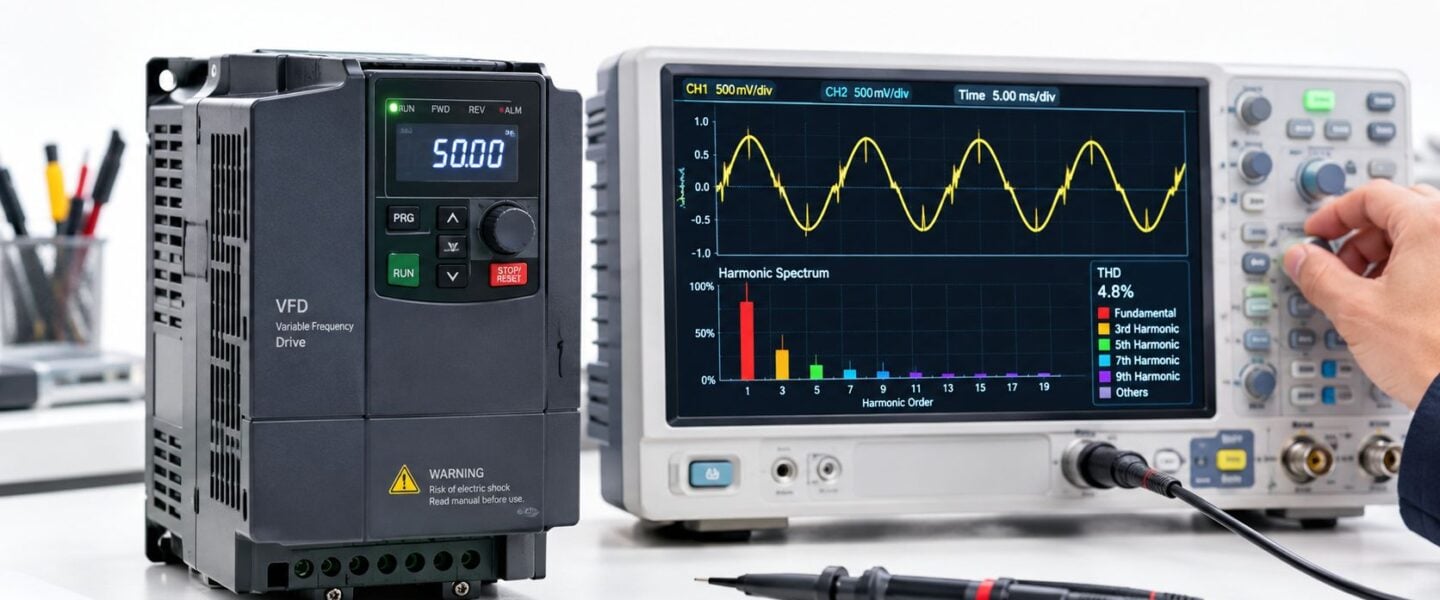
Standard 6-pulse VFDs typically produce about 40% THDi, and some configurations can reach roughly 70% without a DC link reactor. That figure alone doesn't determine compliance, because engineers must evaluate distortion at the point of common coupling, or PCC, using TDD and voltage limits.
A transformer is running hot, a motor control center trips during production changeovers, and operators keep resetting a drive that shows no obvious mechanical fault. In plants with large VFD populations, those symptoms often point to a power-quality problem rather than a failed bearing, overloaded motor, or defective breaker. The practical question is not whether VFDs create harmonics. They do. The question is when distortion is contributing to the failure, how to prove it, and how much mitigation the plant needs.
Table of Contents
- The Hidden Cost of Harmonics in Your Plant
- Understanding VFD Harmonics and Key Metrics
- Conducting Effective VFD Harmonic Measurements
- Mitigation Strategies and When to Use Them
- Impact on Equipment and Compliance with IEEE 519
- Integrating Harmonic Analysis into Reliability Programs
The Hidden Cost of Harmonics in Your Plant
A food-processing plant may have several VFD-controlled pumps, conveyors, and refrigeration compressors operating from the same low-voltage distribution system. The equipment runs normally during a quiet shift, then a capacitor bank trips or a transformer temperature rises when multiple drives accelerate together. Maintenance replaces the breaker, checks motor insulation, and resets the controls. The symptom returns because the investigation never measured the electrical waveform during the operating state that creates the problem.
A VFD is a non-linear load. Instead of drawing current in a smooth sinusoidal pattern, its input rectifier draws current in pulses. Those pulses contain harmonic components, which are frequencies that occur at integer multiples of the fundamental supply frequency. The resulting current distortion can contribute to transformer heating, nuisance operation of protective devices, and voltage distortion across the plant, as described in industrial harmonic-mitigation guidance.
Why the symptoms mislead maintenance teams
Harmonic-related failures rarely announce themselves as a clean, repeatable fault. A motor may overheat without drawing excessive fundamental current. A breaker may trip only when production loads change. A control system may reset when a large drive starts, even though the control power supply tests correctly afterward.
Common field symptoms include:
- Unexpected transformer heat: Harmonic current increases RMS heating stress in transformers and conductors.
- Recurring nuisance trips: Protective devices can respond to distorted current or voltage conditions rather than a sustained overload.
- Capacitor failures: Capacitor banks can interact with system inductance and create resonance, allowing harmonic currents to circulate at damaging levels.
- Motor stress: Harmonic voltages and common-mode effects can contribute to insulation deterioration, bearing pitting, and premature motor failure.
- Intermittent control faults: Sensitive equipment may be affected when distortion rises during a specific combination of drives, generators, or capacitor switching.
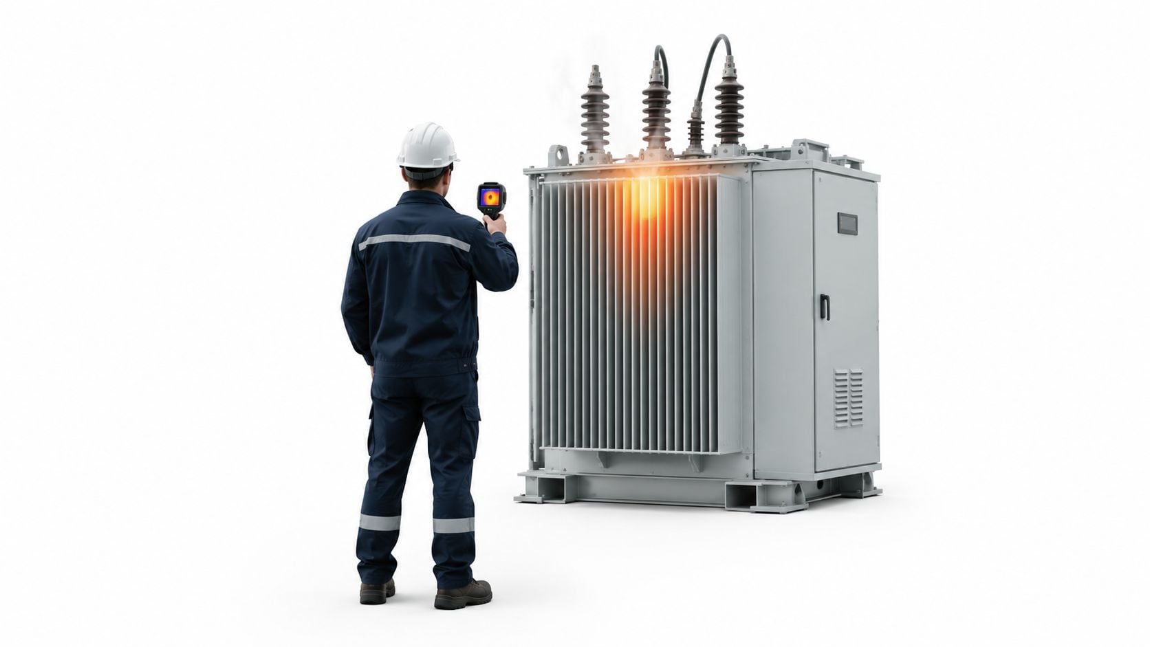
A thermal image can identify a hot connection or overloaded component, but it won't establish whether harmonics caused the heating. That requires synchronized electrical measurements and operating-state correlation.
Practical rule: A hot transformer is a symptom. The reliability decision requires identifying which frequency components rise, under which load conditions, and whether the source is upstream, local, or interacting with compensation equipment.
The reliability case for measuring first
Harmonic analysis becomes valuable when it changes a maintenance decision. If a plant installs filters on every drive without confirming the source, it can spend capital on equipment that doesn't address the dominant condition. If it ignores distortion because individual drives appear to operate normally, it may continue replacing capacitors, breakers, and motors without correcting the common cause.
The strongest investigation connects the electrical data to a physical failure pattern. For example, a pump motor with recurring bearing damage should be evaluated alongside shaft voltage, common-mode behavior, vibration, grounding, and harmonic conditions. The broader diagnostic context can include motor current signature analysis for fault detection, but current signature data shouldn't substitute for PCC power-quality measurements.
Understanding VFD Harmonics and Key Metrics
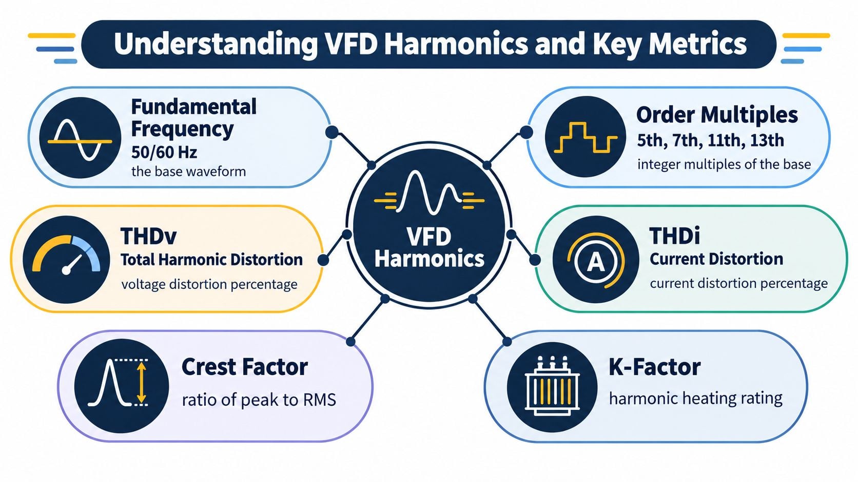
A six-pulse VFD can run within its nameplate ratings while its input current distorts the plant waveform. The fundamental frequency remains the system's base waveform, commonly 50 or 60 Hz. Harmonic order identifies multiples of that frequency. The 5th, 7th, 11th, and 13th harmonics are characteristic low-order components from conventional six-pulse input rectifiers, and they can increase heating, waveform deformation, and stress on connected equipment.
The practical question is not whether harmonics exist. It is whether their magnitude, frequency, and operating pattern match the failure being investigated. A drive-terminal reading may show distortion, yet the plant-level effect can remain limited. Conversely, several moderate sources can combine with a weak source and produce a significant problem at the point of common coupling.
Read the metrics in context
Total harmonic distortion, or THD, expresses the RMS magnitude of harmonic components relative to the fundamental quantity. The measurement must identify whether it describes voltage or current:
- THDv: Voltage harmonic distortion, showing how far the voltage waveform has moved from an ideal sinusoid.
- THDi: Current harmonic distortion at a load, often reported at the drive terminals.
- TDD: Total demand distortion, expressing harmonic current relative to maximum demand load current. This makes it more useful for evaluating system impact at the PCC.
- Crest factor: The ratio of peak current to RMS current, indicating how sharply pulsed the current is.
- K-factor: A transformer heating-related rating that accounts for harmonic current effects.
THDi and TDD answer different diagnostic questions. High THDi at light load may produce a dramatic drive reading without representing the facility's maximum current impact. TDD is better suited to judging demand-related distortion at the PCC. Use both measurements with load data rather than treating either value as a standalone pass or fail result.
Let system strength determine the response
IEEE 519 evaluates harmonic performance at the PCC, rather than only at the drive input. Voltage limits commonly referenced under IEEE 519-2014 are 8% for systems at or below 1 kV and 5% for systems above 1 kV up to 69 kV. Current distortion limits use TDD and depend on the short-circuit ratio, Isc/IL. Industrial guidance cites 5% TDD for many systems with Isc/IL below 20, although the applicable limit depends on the installation and system conditions. These criteria are summarized in guidance on VFD harmonic mitigation and IEEE 519 application.
A high-impedance transformer, generator operation, long feeder, or lightly loaded bus can expose voltage distortion that remains less visible on a stiff source. The same drive can therefore behave acceptably in one operating state and contribute to trips, heating, or capacitor interaction in another.
Use the metrics to decide whether further testing or mitigation is justified. Correlate harmonic magnitude with load, source configuration, and the affected equipment. For motor investigations, motor current signature analysis for fault detection can add diagnostic context, but it does not replace PCC power-quality measurements.
Conducting Effective VFD Harmonic Measurements
A drive trips only during generator operation. A transformer runs hot during a production changeover. Capacitors switch, a control system resets, and a brief waveform disturbance appears at the same time. These events define the measurement campaign. Start by identifying the affected assets, the failure mode, and the operating conditions that precede it. A stable-period reading can miss the condition causing the damage.
Design the study around the failure path
Measure at the point of common coupling, or PCC, because it shows how the facility interacts with the upstream system and how distortion reaches other connected loads. Then work toward the suspect drive or feeder only when the plant-level results and event timing justify that step.
Before installing equipment, map the electrical path. Mark the service entrance, transformers, generator connection, major MCCs, capacitor banks, and VFD feeders. Gather transformer impedance, conductor information, generator details, drive ratings, operating schedules, and capacitor-bank settings. This information determines where a reading will be useful and how source strength may change.
Use power-quality logging equipment rated for the installation and configured to capture:
- voltage and current waveforms
- individual harmonic spectra
- THDv and THDi
- TDD where applicable
- switching events, alarms, and other relevant disturbances
Measure at the PCC first. Add feeder-level or drive-level logging if the PCC record points to a branch, or if the failure occurs only under a specific operating state. Record drive speed, motor load, production status, generator operation, capacitor switching, and nuisance-trip timestamps. Align the waveform record with those timestamps. A harmonic increase that repeatedly coincides with a trip or heating event provides stronger evidence than a high reading with no matching failure.
Panel access requires qualified personnel, appropriate instrument ratings, arc-flash controls, and sound installation practice. Requirements for safe deployment also apply to commercial meter installation.
Record the states that change the diagnosis
Log long enough to include a complete plant operating cycle. Batch processes may require loading, mixing, pumping, cleaning, and changeover. Continuous processes should include normal load variation, generator transitions, large motor starts, and capacitor switching. The goal is to capture the conditions that make the problem appear, not to produce one favorable snapshot.
Track the Isc/IL ratio as the source configuration changes. Isc is the available short-circuit current at the PCC, while IL is the relevant load current. Transformer arrangement, generator contribution, and feeder impedance can alter the voltage response even when the VFD population stays the same.
The useful trend is the operating event that repeatedly precedes the failure, not simply the highest harmonic value in the report.
Pair the electrical record with equipment condition data. A broader condition-monitoring approach for variable-speed drives can combine electrical trends with temperature, vibration, and fault history. That comparison helps separate harmonics from mechanical overload, inadequate cooling, bearing damage, or an unrelated control fault. It also gives reliability engineers evidence to judge whether mitigation spending addresses the root cause.
Mitigation Strategies and When to Use Them
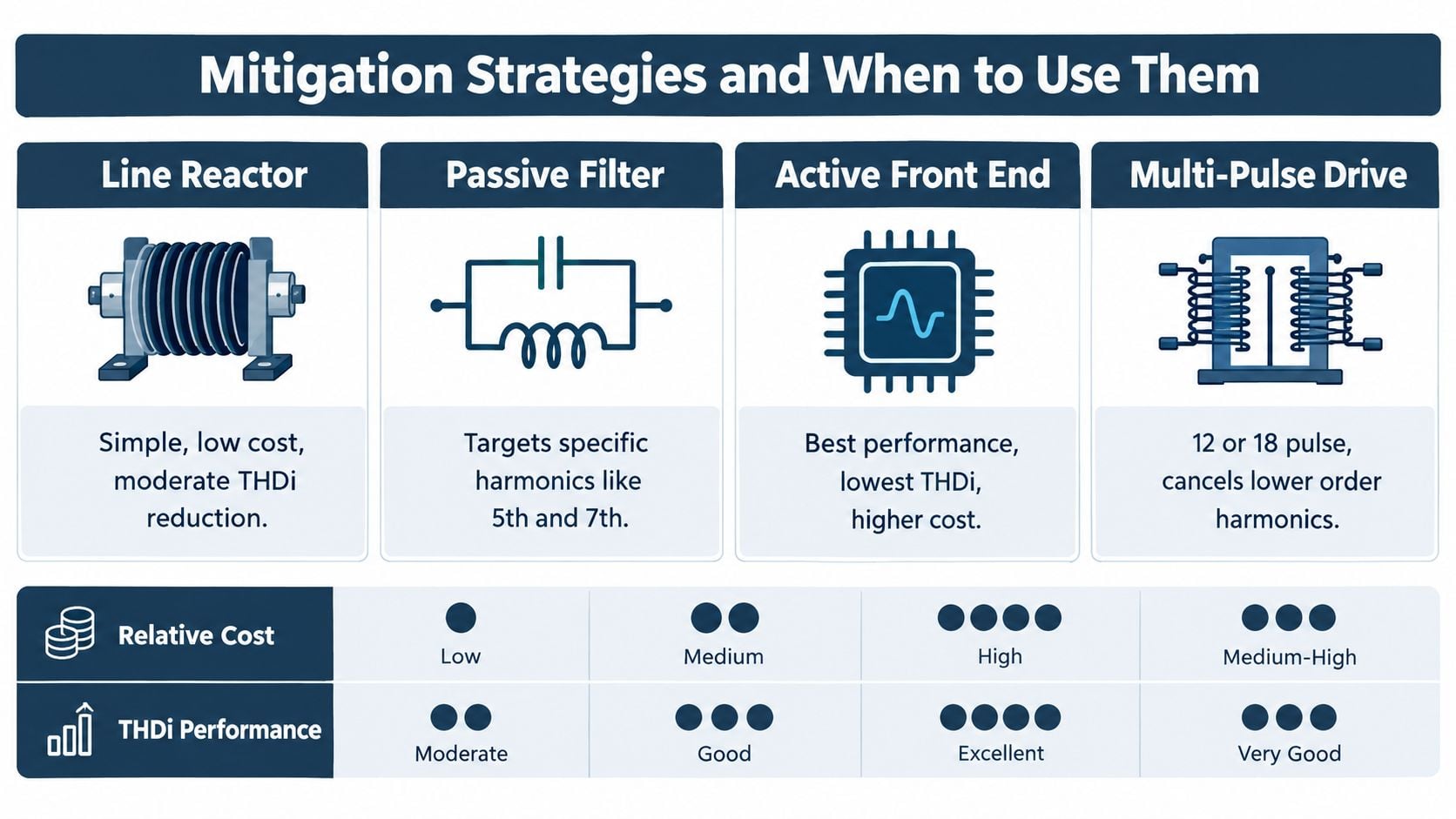
Mitigation should follow diagnosis. The correct choice depends on the harmonic profile, the PCC result, the available enclosure space, the electrical topology, the sensitivity of connected loads, and the consequence of failure. A line reactor may solve a modest drive-feeder problem, but it won't always address a plant-wide interaction involving multiple drives and capacitor banks.
Start with the least complex effective option
A 3% to 5% impedance line reactor is commonly used to limit VFD-generated harmonics and reduce disturbance on the distribution system, according to IEEE technical guidance on power-system harmonics. It is often a practical first step for a new drive or a feeder with moderate distortion, especially when the plant needs input-current smoothing, additional impedance, or improved drive protection.
The trade-off is voltage drop, heat, and limited control over a broad plant harmonic profile. A reactor at one drive won't correct resonance at a remote capacitor bank or distortion created by a group of drives sharing a weak bus.
Passive filters use tuned components to target selected frequencies, commonly the dominant low-order harmonics. They can provide focused correction, but their design must account for system impedance and resonance. An incorrectly selected filter can create a new interaction rather than remove the original one.
Escalate when the operating risk justifies it
An active front end uses controlled switching to shape input current and can provide low harmonic current with near-unity power factor. It offers strong performance where space, regenerative operation, or stringent power-quality requirements justify higher complexity and cost. The plant must still evaluate controls, cooling, service capability, and lifecycle implications.
Multi-pulse drives, such as 12-pulse or 18-pulse arrangements, reduce selected lower-order harmonics through phase-shifting and cancellation. They can work well in large fixed installations, but their transformers occupy space and add system components that require maintenance. They aren't automatically the best answer for a retrofit with limited room or changing process loads.
A decision matrix should connect each option to the failure it is meant to prevent:
| Plant condition | Practical first consideration | Main trade-off |
|---|---|---|
| One feeder shows moderate distortion | Line reactor | Limited plant-wide effect |
| Dominant 5th and 7th components create a known interaction | Passive filter | Requires careful tuning |
| High sensitivity, strict performance needs, or regenerative duty | Active front end | Higher complexity and capital cost |
| Large, stable drive installation | Multi-pulse topology | Added transformer and footprint |
The investment case becomes stronger when the mitigation target is specific. If a capacitor bank fails after a predictable switching condition, the study should test resonance and verify the correction at the PCC. If a control system trips only when several compressors run, selective correction at the worst feeders may be more defensible than installing hardware on every drive. Plant optimization work for VFD applications can also help align drive operation, loading, and energy objectives, as outlined in variable-speed-drive plant optimization.
Impact on Equipment and Compliance with IEEE 519
A VFD-driven fan can leave a transformer running hotter than expected even when the fundamental load remains within its rating. A water-treatment facility may see capacitor failures after adding drive-controlled pumps. An automated packaging line may reset when several machines accelerate together. These symptoms justify harmonic analysis, but they do not prove harmonics are responsible. Loose connections, inadequate cooling, overload, transients, grounding faults, and control problems can produce similar results.
Start with the affected asset and operating condition. Compare transformer temperature with demand and harmonic current, check capacitor current and resonance during switching, and correlate control resets with simultaneous drive acceleration. The diagnostic question is whether the harmonic component changes with the failure and whether its magnitude can produce the observed stress.
The equipment consequences are specific:
- Transformers and conductors: Harmonic current adds heating and reduces thermal margin.
- Motors: Harmonic and common-mode effects can contribute to insulation stress, bearing pitting, and premature failure.
- Capacitor banks: Resonance can increase current and accelerate capacitor damage.
- Protective devices: Distorted current can contribute to nuisance operation.
- Cables and neutral conductors: Harmonic current adds thermal stress.
- Sensitive controls: Voltage distortion and electrical noise can disrupt equipment that depends on clean power.
The industrial harmonic-effects reference covers transformer, motor, cable, capacitor, insulation, and bearing concerns. A motor insulation test adds useful evidence, but interpret the result alongside operating temperature, voltage stress, grounding, cable length, and waveform conditions. Motor insulation resistance testing should therefore support, rather than replace, the wider electrical diagnosis.
IEEE 519 applies at the system level. It separates voltage distortion from current distortion and evaluates current with TDD, rather than relying only on a drive's instantaneous THDi. Commonly referenced voltage limits for low-voltage systems are 8% at or below 1 kV and 5% from above 1 kV through 69 kV. Current limits depend on Isc/IL. The practical question is whether the aggregate nonlinear load is stressing the facility, not whether one drive produces an acceptable terminal reading.
Document the PCC location, measurement window, system configuration, demand current, harmonic spectrum, and operating state. Statistical measurement methods and defined aggregation intervals also matter, so align the test plan with the applicable edition and contractual requirements.
Compliance alone does not set the repair priority. If thermal evidence, repeated trips, or resonance coincide with high harmonic measurements, quantify the operating consequence and mitigation cost. If the correlation is weak, investigate other causes before funding harmonic correction. This approach identifies when harmonics are the root cause and how much reduction is needed to protect the asset.
Integrating Harmonic Analysis into Reliability Programs
Harmonic analysis works best as part of a condition-based reliability program. Establish a baseline at the PCC and on critical VFD feeders, then relate harmonic trends to transformer temperature, motor vibration, capacitor condition, drive alarms, and production state. Alarm thresholds should reflect the facility's applicable limits and the operating consequence of crossing them, rather than relying on a generic drive-terminal value.
A recurring investigation workflow can be simple:
- Screen the symptom: Confirm the time, asset, load state, and failure mode.
- Measure the system: Capture PCC voltage, current, harmonic content, and demand conditions.
- Correlate the evidence: Compare electrical trends with thermography, vibration, motor current, and event logs.
- Prioritize the intervention: Correct the feeder or interaction that contributes most to the reliability risk.
- Verify the result: Repeat measurements under the same operating conditions after mitigation.
A plant-wide condition-monitoring system can provide the structure for combining these data streams. The outcome should be a defensible decision, not merely a harmonic report.
Forge Reliability provides power-quality measurements, harmonic distortion assessments, and mitigation recommendations for VFD systems, including drive-level and distribution-level investigations. Visit Forge Reliability to request a free reliability assessment and identify whether harmonics are contributing to recurring trips, overheating, capacitor failures, or motor damage at your facility.