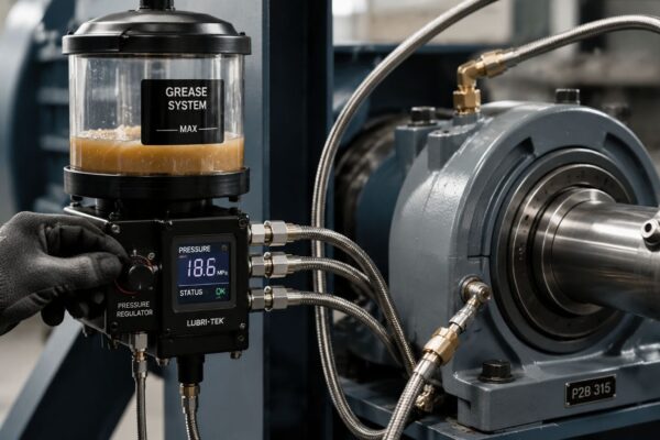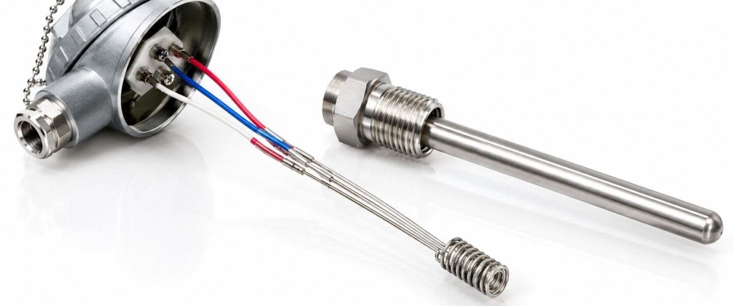
A compressor bearing alarm can look convincing on the HMI while the bearing itself is healthy. The temperature is within the configured range, the transmitter reports a normal status, and the PLC sees a plausible signal. Then the trip occurs after a field modification, a junction-box rebuild, or a sensor replacement, and the investigation starts in the wrong place.
That pattern is common with an RTD thermal sensor because the measurement is a system, not just a probe. The sensing element, lead wires, thermowell interface, transmitter, and PLC channel can each introduce a quiet bias. None of those faults necessarily creates a clean wire-break alarm.
Table of Contents
- When the RTD Looks Fine but the Reading Is Wrong
- How RTDs Measure Temperature and Why Platinum Dominates
- Choosing Between 2-Wire 3-Wire and 4-Wire RTD Connections
- Thermowells Installation and the Hidden Cost of Slow Response
- Calibration and Validation Procedures That Catch Drift Early
- Common Failure Modes and a Field Troubleshooting Sequence
- Integrating RTD Signals with PLCs RTUs and Predictive Systems
- Selecting the Right RTD for Steam Bearings and Process Lines
When the RTD Looks Fine but the Reading Is Wrong
A compressor bearing housing can show a credible temperature while the bearing remains healthy. After a conduit reroute, the Pt100 loop continued displaying a plausible value on the HMI, yet added series resistance shifted the apparent temperature high enough to initiate a trip. The bearing did not overheat. An error entered the measurement chain.
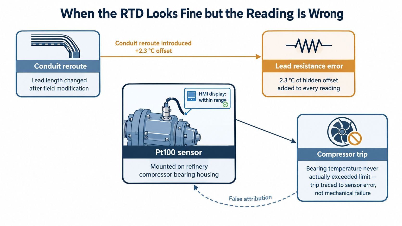
Trace the loop through five layers:
- Sensing element: The platinum element can drift, develop an intermittent connection, or heat itself through excessive measurement current.
- Lead wire: Conductor resistance, corrosion, moisture, and unequal wire lengths can change the resistance reaching the transmitter.
- Thermowell interface: Shallow immersion, a loose insert, fouling, or a thick wall can slow heat transfer and leave the element behind the actual process temperature.
- Transmitter: The wrong probe type, resistance standard, alpha coefficient, scaling, or excitation setting can produce a believable output with the wrong value.
- PLC analog channel: Range, engineering-unit scaling, filtering, alarming, or channel configuration can hide the evidence or shift the displayed reading.
Three quiet distortion patterns
A junction-box rebuild can leave a three-wire loop with conductors that no longer match closely. The transmitter still receives a valid resistance signal, but its lead compensation becomes inaccurate. Three-wire measurement reduces lead error only when the relevant conductor resistances are closely matched. Four-wire measurement separates the current and sensing paths more effectively. The practical wiring guidance in this instrument manual also identifies maximum lead-resistance limits for three-wire and four-wire operation.
A shallow installation creates a thermal-location error. The stem can conduct heat toward a cooler pipe wall or mounting boss, so the element never reaches the true process temperature. Calibration may be correct at the transmitter while the sensor reports the temperature at the wrong location.
A partially open element can be equally deceptive. A damaged connection may increase resistance without opening the circuit completely. The transmitter continues producing a value within its configured range, and the PLC sees no hard fault. Compare the reading with a reference thermometer, then check resistance while flexing the transition area. That sequence can expose an intermittent defect.
Practical rule: Treat every temperature trip as a loop investigation before treating it as an equipment failure. A plausible signal does not prove a correct signal.
Judge the complete installed system against the speed, location, and uncertainty the protection logic requires, not just the bench check.
How RTDs Measure Temperature and Why Platinum Dominates
An RTD can look electrically healthy while the installed loop reports the wrong temperature. The sensing element, lead wires, thermowell, transmitter, and PLC input all influence the final value. A bearing, reactor, or steam line can therefore drift from its real temperature without producing a wire-break alarm.
An RTD measures temperature through resistance. As the platinum element heats, stronger atomic vibration restricts electron flow and raises resistance. The instrument measures that change, then converts it into a temperature value.
A Pt100 has a nominal resistance of 100 Ω at 0 °C. A Pt1000 has 1,000 Ω at 0 °C, so fixed lead resistance forms a smaller part of the measured signal. Pt1000 can suit compact assemblies and longer connections, provided the transmitter and PLC input are configured for that element.
The conversion follows the Callendar-Van Dusen relationship, a mathematical model that relates resistance to temperature across the operating range. The transmitter must match the element's resistance standard and alpha coefficient. A device configured for a 100 Ω platinum sensor conforming to DIN 43760 with alpha = 0.00385 can report an incorrect value when connected to a different sensor type or coefficient. The instrument manual describing this requirement shows why configuration belongs in the commissioning record as well as the instrument settings.
Platinum dominates because it offers chemical stability, repeatable behavior, and a predictable resistance response. Nickel and copper can fit narrower applications, while demanding plant measurements usually prioritize stability and repeatability over catalog price.
Construction changes field behavior
A thin-film RTD deposits platinum on a ceramic substrate. Its compact construction can support fast response, but the package, probe geometry, and mounting method still control how quickly it follows the process. A wire-wound RTD uses fine platinum wire and can provide stable measurement in demanding service. Its larger construction may respond more slowly, and unsupported assemblies can suffer from vibration.
Accuracy class is only one selection factor. A tightly toleranced sensor can still report the wrong process value because of lead resistance, self-heating, immersion error, thermal gradients, thermowell contact, or transmitter scaling. The PLC may accept that value as valid because none of these conditions necessarily creates an open circuit.
| Parameter | Pt100 thin-film | Pt1000 thin-film | Pt100 wire-wound |
|---|---|---|---|
| Nominal resistance | 100 Ω at 0 °C | 1,000 Ω at 0 °C | 100 Ω at 0 °C |
| Main advantage | Compact industrial construction | Greater signal resistance relative to lead resistance | Strong stability for demanding measurement |
| Main risk | Package and mounting can affect response | Requires compatible input and configuration | Mechanical construction can affect vibration and response |
| Reliability focus | Verify installation and self-heating | Confirm transmitter range and wiring | Check support, vibration exposure, and thermal lag |
Self-heating needs an installed-system check. Excitation current warms the element, and the resulting error depends on construction and heat transfer. The sensor fundamentals guidance from the instrumentation manufacturer describes typical self-heating coefficients ranging from about 2.5 mW/°C for small thin-film elements to 65 mW/°C for larger wire-wound elements. The same excitation can produce different errors in air, stagnant fluid, flowing liquid, or a poorly fitted thermowell. Verify the complete loop under its actual operating conditions, not only the element on a bench.
Choosing Between 2-Wire 3-Wire and 4-Wire RTD Connections
A temperature loop can look healthy while reporting the wrong value. The element may be within tolerance, the transmitter may show a stable signal, and the PLC may see no wire-break alarm. Lead resistance, terminal condition, cable routing, and input configuration can still bias the reading. Treat the RTD as a system of sensor, conductors, transmitter, and PLC channel, not as an isolated probe.
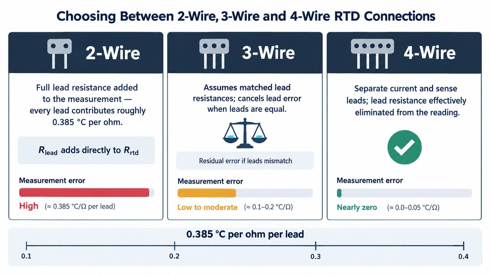
For a nominal 100 Ω platinum RTD with an IEC/DIN coefficient of approximately 0.385 Ω/°C, each uncompensated 1 Ω of series resistance produces roughly 2.6 °C of apparent temperature error. The instrument documentation covering RTD lead resistance supports this practical calculation.
Two-wire connections
A two-wire circuit adds the resistance of both conductors to the element resistance. The instrument cannot distinguish cable resistance from the RTD, so the indicated temperature usually shifts high. The error becomes more difficult to control on long runs, warm cable trays, or circuits that have been rerouted.
Two-wire wiring can suit a bench test, a short cabinet connection, or a stable loop calibrated with its installed cable. It is a poor default for a bearing, reactor jacket, or heat-treatment furnace where a biased reading can alter control action or trip decisions. Cable temperature, terminal resistance, and later modifications can change the error after commissioning.
Three-wire connections
Three-wire wiring is common in plant service because the transmitter compares matched lead paths and subtracts approximately equal resistance from the measurement. The method works when the conductors have the same type, length, temperature exposure, and condition.
Compensation becomes incomplete when one conductor corrodes, a terminal loosens, or one leg takes a different route through the plant. Specify tightly matched conductor resistance and record each loop resistance during commissioning. One instrument manual specifies 10 Ω maximum lead resistance per lead for three-wire operation and identifies four-wire probes for applications requiring maximum accuracy.
Four-wire sensing
Four-wire, or Kelvin, measurement separates the force conductors that carry excitation current from the sense conductors that measure voltage. The sense circuit draws very little current, so conductor resistance has far less effect at the instrument input.
Use four-wire sensing for reactor jackets, bearing-oil systems, furnaces, and high-value process skids when the consequence of a biased reading justifies extra conductors and compatible input hardware. It is not an automatic retrofit choice. The same documentation specifies 50 Ω maximum lead resistance per lead for four-wire operation, while the main practical advantage remains the measurement method and its reduced sensitivity to lead resistance.
| Connection | What works | What fails |
|---|---|---|
| Two-wire | Short, fixed connections and controlled bench work | Long runs, cable reroutes, and critical trips |
| Three-wire | General plant loops with matched conductors | Unequal resistance, corrosion, and different cable paths |
| Four-wire | Critical measurements and high-accuracy applications | Incompatible input hardware or poorly documented retrofits |
Field decision: Use two-wire only when cable resistance is demonstrably insignificant or included in calibration. Use three-wire for general plant service with verified conductor symmetry. Use four-wire when the consequence of a biased reading warrants extra conductors and compatible instrumentation.
A three-wire check should compare conductors individually, not merely confirm continuity. A warmer tray, corroded spare terminal, or replacement leg from a different cable can leave residual error. Also verify transmitter range, sensor type, and PLC scaling, because correct wiring cannot compensate for an incorrect input configuration.
Thermowells Installation and the Hidden Cost of Slow Response
A thermowell is a mechanical barrier between the process and the RTD insert. It protects the sensor from pressure, flow, corrosion, and contamination, but it also adds thermal mass and another heat-transfer path. Selecting one only by connection size or material can create a measurement that is mechanically secure but operationally late.
Consider a superheated steam line feeding a process heat exchanger. A thick straight well may survive the service, yet the sensor can report a rounded version of a rapid steam-temperature excursion. In a jacketed reactor, the same delay can hide a charging upset while the control system continues acting on an older temperature value.
Endress+Hauser industrial RTD assemblies define response time as the time required to reach 63% of the final temperature change under ASTM E644. Published assembly values range from approximately 20 to 35 seconds, with tapered thermowells responding in about 20 to 25 seconds and a ¾-inch straight thermowell requiring roughly 30 to 35 seconds, depending on geometry and process conditions. Those values are assembly-specific, so the installed response must be verified rather than assumed.
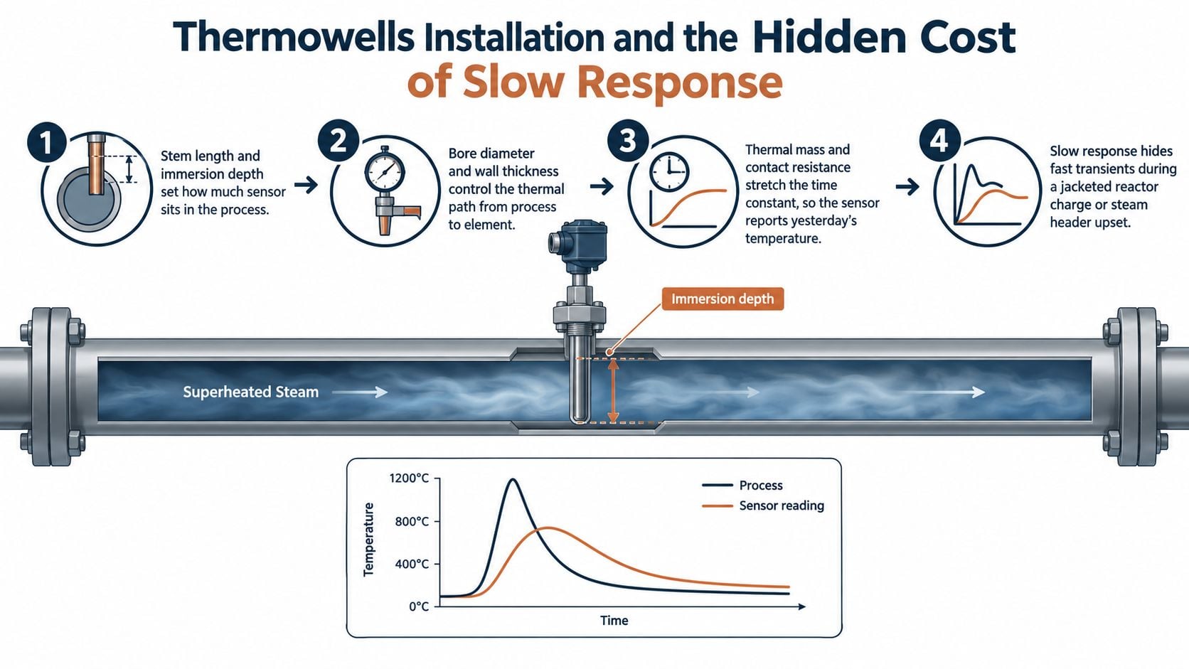
Geometry and thermal contact
Four details control much of the response:
- Immersion depth: The element must sit far enough into the flowing medium to measure the process rather than the pipe wall or nozzle.
- Bore fit: Excessive clearance between the insert and the well creates an insulating gap. A loose insert can respond slowly and inconsistently.
- Wall thickness: More metal between the fluid and element can improve strength while increasing thermal delay.
- Fouling and deposits: Process residue adds thermal resistance and can change the effective response over time.
The well also has a mechanical duty. Flow-induced vibration, wake frequency, unsupported length, and material compatibility must be reviewed together. A thinner or tapered design may respond faster, but it must still withstand the process forces and corrosion environment. Stainless steel, high-alloy materials, and ceramic constructions each bring different strength, corrosion, and thermal characteristics. Material selection should follow the process chemistry and mechanical calculation, not a generic preference.
Control-loop consequences
A slow thermowell can make a stable control loop look well tuned. Operators may increase controller aggressiveness to compensate, then create overshoot when the process changes or the sensor catches up. The transmitter update rate cannot remove thermal lag inside the well.
A steam-system inspection should include the well, insulation, traps, and nearby heat-loss paths. A practical guide to thermographic surveys of steam systems, traps, and insulation can help identify surrounding thermal conditions that make an RTD reading difficult to interpret.
The protection question is simple: can the complete RTD and thermowell assembly respond within the time available to protect the equipment? If the answer isn't known, the loop has an unverified protection dependency.
Calibration and Validation Procedures That Catch Drift Early
Calibration should begin with the process envelope, not a convenient shop temperature. A sensor used on a reactor jacket, bearing-oil system, or refrigeration discharge should be checked at temperatures that bracket its actual duty. A single ambient check can confirm wiring continuity while missing the error that matters during operation.
NIST industrial platinum-resistance-thermometer calibrations demonstrate expanded uncertainties of approximately 2.3 mK at −196 °C, 2.4 mK from 0.5 to 95 °C, 4.8 mK from 95 to 275 °C, and 7.5 mK from 275 to 550 °C when compared with ITS-90-traceable standards. NIST's industrial thermometer calibration information makes an important distinction: calibration capability is not the same as total installed-system error. Field error also includes sensor tolerance, transmitter accuracy, wiring, immersion, thermal gradients, and response lag.
A field-grade sequence
- Record the as-found condition. Capture the indicated process value, reference value, test point, loop configuration, and whether the sensor is installed or removed.
- Use a suitable reference. A dry-block calibrator or comparison bath should cover the operating points that matter. The reference standard must be traceable and appropriate for the temperature range.
- Stabilize before recording. Allow the sensor and reference to reach thermal equilibrium. A fast reading taken before stabilization can be mistaken for drift.
- Compare at multiple points. A single-point pass can conceal a slope error, configuration mismatch, or temperature-dependent insulation problem.
- Document as-left results. Record adjustment, replacement, or no-action decisions separately from the original as-found values.
- Trend the deviation. Store the result in the CMMS against the asset and loop, rather than leaving it in an isolated spreadsheet.
Drift points toward different causes
| Drift at 0 °C | Probable cause | Field action |
|---|---|---|
| Positive offset | Added lead resistance, terminal resistance, or scaling mismatch | Compare conductor resistance, inspect terminals, verify configuration |
| Negative offset | Insulation degradation or a shunt path to the sheath | Inspect moisture and insulation, then perform insulation testing |
| Unstable result | Loose connection, vibration damage, or moisture ingress | Flex-test the transition, inspect glands and junction boxes |
| Increasing deviation | Element aging, overheating, or repeated thermal cycling | Review service history and shorten the verification interval |
| Consistent error after replacement | Wrong resistance standard or alpha coefficient | Confirm probe type and transmitter configuration |
Calibration intervals should be risk-based, not automatically calendar-based. A stable, low-consequence temperature loop may justify a longer interval after repeated in-tolerance results. A sensor exposed to thermal cycling, vibration, aggressive chemicals, or a high-consequence trip needs closer attention. The maintenance discussion of dissolved oxygen sensor verification illustrates the same discipline, namely separating as-found condition, corrective action, and trend history.
A growing offset should trigger an investigation before replacement. Moisture ingress, thermowell fouling, loose terminals, and transmitter configuration errors can all survive a sensor swap.
Common Failure Modes and a Field Troubleshooting Sequence
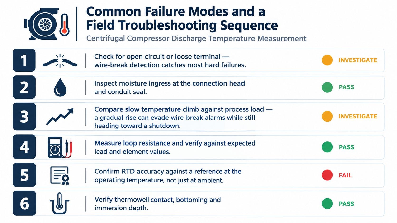
A centrifugal compressor discharge RTD can climb slowly while the wire remains electrically intact. The result may be an unnecessary shutdown, or a missed thermal problem, because the loop reports a plausible value. Treat the measurement as a system: element, leads, thermowell, transmitter, and PLC channel. Replacing the transmitter first can erase evidence without showing which layer introduced the error.
Start with the loop
Compare the indicated temperature with process load, an independent sensor, and a calibrated reference when conditions permit. A rise that does not track load or the second sensor suggests measurement bias. If independent channels rise together, investigate the process, bearing, compressor, or reactor condition instead of assuming an RTD fault.
Check the signal path in a fixed order:
- Open circuit: Test the element, transition, terminals, and cable continuity. A broken element or conductor may remove the reading or force the configured fault state.
- Grounded or shunted element: Inspect moisture, sheath contact, insulation damage, and contaminated junction boxes. A parallel path can lower apparent resistance and report a falsely low temperature.
- Drifting value: Measure resistance at the operating condition, confirm the transmitter's sensor type and alpha coefficient, and compare the result with a traceable reference.
- Noisy signal: Examine terminal tightness, shielding and grounding, vibration at the transition, and cable movement during operation.
- Unexpectedly high value: Measure each lead separately. Added series resistance after a reroute or terminal rebuild can bias the reading upward.
- Slow response: Check thermowell deposits, insert fit, bottoming, immersion, and process contact before blaming the control system.
Mechanical vibration often damages the element-to-lead transition first. Repeated shock can produce an intermittent open circuit before the conductor separates completely. Heat, chemicals, and moisture can also degrade insulation, allowing the sheath to create a parallel path that biases the signal without triggering a wire-break alarm.
Check excitation and thermal conditions
Excitation current heats the sensing element. The resulting error depends on RTD construction and heat transfer, so the same transmitter setting can behave differently in air, stagnant fluid, flowing liquid, or a poorly fitted thermowell. Measure the excitation current and review the sensor's installation rather than treating self-heating as a fixed correction. The sensor measurement guidance on self-heating and RTD construction explains why element size and construction affect this error.
Use the field evidence to choose the action:
- Replace the sensor or cable when the element is damaged, insulation has failed, or vibration has weakened the transition.
- Clean and inspect the thermowell when deposits, corrosion, or poor insert contact explain the lag.
- Re-calibrate when the hardware is sound and the deviation is stable, traceable, and linked to configuration or manageable drift.
- Escalate to equipment analysis when independent measurements agree and process or bearing conditions support a genuine thermal event.
Document the physical cause, not only the failed component. A structured root-cause failure analysis resource can help connect recurring failures to vibration, moisture, cable routing, process chemistry, or maintenance workmanship across similar compressors and pumps.
Integrating RTD Signals with PLCs RTUs and Predictive Systems
The signal path deserves the same scrutiny as the sensor. A four-wire RTD may feed a smart transmitter, which sends a conditioned analog or digital value to a PLC. The PLC then applies scaling, filtering, alarm limits, interlocks, and status handling before an RTU or predictive system receives the value.
A healthy design separates process faults from sensor-health faults. High bearing temperature, open circuit, out-of-range resistance, transmitter diagnostic failure, and stale telemetry shouldn't all appear as the same alarm. Operators need to know whether the compressor is overheating or whether the measurement has become unavailable.
Remote assets create another risk. An RTU scan rate, input resolution, filtering setting, or communications delay can flatten a gradual bearing-warning trend. The local protection channel should remain responsible for immediate action, while the supervisory system preserves enough context for diagnosis and trending.
Make bias visible
A second RTD can expose a biased primary sensor when both are installed at comparable thermal reference points. Voted logic can also prevent one implausible channel from tripping a compressor, but voting only works when the channels are physically independent enough to avoid sharing the same cable, junction-box, or thermowell failure.
Useful predictive rules include:
- Rolling baseline: Compare current temperature with the asset's normal operating range under similar load.
- Rate of change: Flag a sustained climb before the absolute trip threshold is reached.
- Cross-channel comparison: Compare redundant RTDs, discharge temperature, bearing vibration, and process load.
- Signal quality: Trend bad-quality flags, frozen values, open circuits, and configuration changes separately from temperature.
Integration projects often fail at the boundaries between instrumentation, controls, communications, and maintenance ownership. The integration challenges practical guide is a useful resource for reviewing those handoffs without treating the PLC channel as an isolated component.
A PLC and SCADA review should verify scaling from resistance to engineering units, alarm deadbands, sensor-failure behavior, time stamps, and historian quality flags. This guide to PLC integration with SCADA provides relevant context for checking whether the control-system representation matches the installed measurement.
Selecting the Right RTD for Steam Bearings and Process Lines
Selection starts with the measurement point, its operating conditions, and the consequence of a bad reading. An RTD loop includes the element, leads, thermowell or mounting, transmitter, and PLC channel. Each layer can bias a bearing, reactor, or steam reading without producing a wire-break alarm.
A steam-line RTD needs mechanical protection, adequate immersion, and materials suited to pressure, temperature, and corrosion. A bearing sensor needs low mass, close thermal contact, a protected lead transition, and mounting that stays stable under vibration. A sanitary process sensor requires cleanability, compatible materials, and documented surface requirements.
For superheated steam, a mineral-insulated Pt100 inside a stainless thermowell can combine mechanical protection with effective heat transfer. A high-pressure flanged connection may suit the process pressure and site maintenance method. Check thermowell geometry for flow-induced vibration and response time. Confirm that the element, transmitter, and PLC use the same resistance standard and scaling.
Rolling-element bearings often suit a Pt1000 potted near the housing surface, with a low-profile lead exit and spring-loaded mounting to maintain contact. Review the housing temperature gradient, vibration exposure, cable strain relief, and replacement access. A sound element can still report poorly if the lead transition flexes at every machine cycle.
Sanitary lines require different priorities. Specify a welded thermowell designed for cleanability, a suitable hygienic connection, a smooth process-facing finish, and a four-wire Class A element where product quality depends on the reading. Follow the site hygienic design standard and validation procedure for the final specification.
| Application | Element | Thermowell or mounting | Key selection note |
|---|---|---|---|
| Superheated steam line | Mineral-insulated Pt100 | Stainless thermowell with a pressure-rated connection | Balance response, strength, vibration, and corrosion |
| Compressor or motor bearing | Compact Pt1000 | Close-contact, spring-loaded mounting | Protect the lead transition from vibration and strain |
| Reactor jacket | Four-wire platinum RTD | Immersed thermowell selected for chemistry and flow | Prioritize measurement integrity and response during thermal transients |
| Food or pharmaceutical line | Four-wire Class A element | Hygienic welded thermowell or approved sanitary mounting | Verify cleanability, material compatibility, and documented finish |
| Industrial refrigeration | Platinum RTD matched to transmitter range | Sealed connection and suitable immersion assembly | Control moisture ingress and verify low-temperature calibration |
A steam turbine maintenance program should review temperature sensors with vibration, lubrication, insulation, and thermowell condition. This resource on steam turbine maintenance helps maintenance teams judge whether an RTD issue is isolated or part of a wider turbine reliability problem.
For a critical loop, record the element type, resistance standard, alpha coefficient, wiring topology, cable construction, thermowell material, immersion arrangement, transmitter configuration, PLC scaling, alarm behavior, and calibration points. This record prevents a replacement from inadvertently altering the measurement system.
Aim for a measurement chain whose accuracy, response, mechanical durability, and diagnostic behavior match the asset's consequence, even when that means a modest probe with excellent supporting wiring.
Forge Reliability can assess RTD loops across compressors, pumps, steam systems, reactors, refrigeration equipment, and critical process lines, including sensor selection, wiring symmetry, thermowell response, calibration history, and PLC alarm behavior. Visit Forge Reliability to request a reliability assessment and identify whether recurring temperature problems originate in the sensor, installation, instrumentation, or equipment.