Many plants still treat shaft alignment as a setup task. That overlooks the significant risk. About 90% of machines operate outside recommended alignment tolerances, and the same industry source notes that in some industrial sectors, misalignment contributes to more than 50% of machine downtime.
For a plant manager, that changes the conversation. Misalignment of shaft isn't just a maintenance detail. It's a repeat-failure mechanism that shortens bearing life, opens seals, damages couplings, raises vibration, and steadily pushes operating cost in the wrong direction. The difficult part is that many machines look acceptable at rest, pass a quick visual check, and still run out of tolerance once process conditions come into play.
The problem gets harder when thermal growth, pipe strain, looseness, and other faults overlap. A pump may be aligned during shutdown and still run badly after startup. A fan may show a vibration pattern that looks like unbalance, while misalignment is part of the failure chain. The practical answer isn't more theory. It's disciplined diagnosis, correction, and verification under real operating conditions.
Table of Contents
- The High Cost of a Seemingly Small Problem
- Finding Root Causes Beyond the Obvious
- Diagnosing Misalignment with Confidence
- A Modern Guide to Precision Alignment and Correction
- Selecting Tolerances and Verifying the Fix
- Building a Proactive Misalignment Control Strategy
The High Cost of a Seemingly Small Problem
Misalignment of shaft starts as a geometric error, but it ends as a reliability and cost problem. When two coupled shafts don't share the same operating centerline, the machine runs under continuous side loading and cyclic stress. That force doesn't stay at the coupling. Bearings absorb it. Seals absorb it. The base and hold-down hardware feel it. The motor and driven equipment both pay for it.
For plant leadership, the financial issue is straightforward. A machine can keep producing while misaligned, but it does so while consuming useful life. The result shows up later as repeat work orders, premature part replacement, nuisance trips, and downtime that seems disconnected from the original setup error. Teams focused on maintenance cost reduction strategies usually find that alignment discipline belongs high on the list because it influences several failure modes at once.
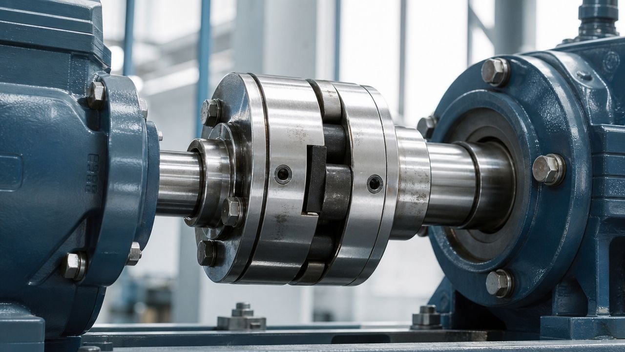
What misalignment really means on the plant floor
Three patterns matter most in coupled machines:
- Parallel misalignment means the shaft centerlines are offset from each other, even if they remain parallel.
- Angular misalignment means the shafts meet at an angle instead of along one straight line.
- Combination misalignment means both conditions exist together, which is common in actual equipment.
A motor and pump set is a good example. If the motor sits slightly high at one pair of feet, the machine may show angular error. If piping pulls the pump sideways after bolting up, the centerlines may shift into parallel offset. Most field cases are some combination of both.
Practical rule: If a machine repeatedly consumes bearings, seals, or couplings without an obvious lubrication or process problem, alignment belongs on the short list immediately.
Misalignment also creates an efficiency penalty. The machine has to fight internal mechanical forces that shouldn't be there. Operators may not notice that loss directly, but they will notice more heat, more vibration complaints, and more maintenance intervention than comparable assets on the same site.
Finding Root Causes Beyond the Obvious
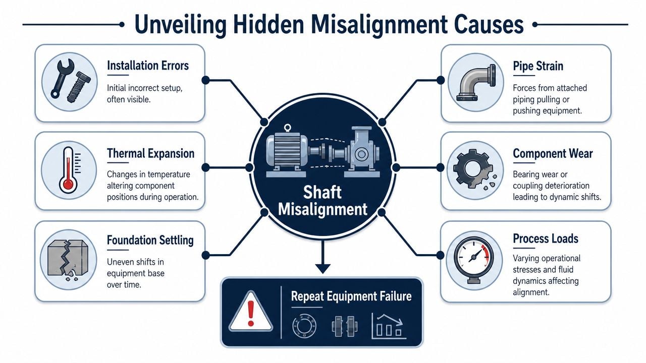
Installation error is a known cause of misalignment. The harder cases are the machines that were aligned correctly during outage work and still return with the same symptoms. That's where root cause work matters more than another quick adjustment. A primary reason for recurring misalignment is failure to account for dynamic conditions like thermal growth and pipe strain, which can make a correct cold alignment useless in operation (Maintenance World on thermal growth and pipe strain).
A hot-process pump in a chemical plant shows this clearly. During shutdown, the pump and motor are cool, isolated, and easy to access. The alignment comes into tolerance. Once the line heats up and product starts moving, the casing expands, support conditions change, and connected piping can apply force to the pump nozzles. The machine that looked correct on the floor no longer runs on its intended centerline.
Why hot equipment moves after a perfect cold alignment
Thermal growth is the change in machine position caused by temperature increase during operation. Not every machine moves enough to matter, but critical pumps, compressors, turbines, and fan trains often do. If one machine grows vertically or horizontally more than the other, the coupling relationship shifts.
Pipe strain happens when connected piping pushes or pulls on the machine casing. This usually comes from poor fit-up, unsupported line weight, thermal movement in the piping system, or maintenance work that forced the piping into place rather than correcting the piping support issue.
Soft foot is a mounting condition in which one or more machine feet don't sit flat on the base. Tightening the hold-down bolts distorts the frame and corrupts the alignment readings before the machine even starts.
What to inspect before touching the alignment
A useful field sequence looks like this:
- Confirm base condition. Check hold-down bolts, grout condition, base flatness, and obvious looseness.
- Check soft foot first. If the machine frame is distorted, every alignment value that follows is suspect.
- Evaluate pipe strain. Loosen the pipe connection in a controlled way, where safe and appropriate, and watch for movement at the machine.
- Review operating temperatures. Cold readings matter, but hot running position is what determines shaft centerline in service.
- Decide whether the machine or the system is wrong. Sometimes the alignment is only a symptom, and the underlying defect sits in piping, base distortion, or worn components.
A boiler feed pump provides a good example. If technicians align the motor to the pump but skip pipe strain checks, the machine may pass the outage work pack and fail again after startup. The second failure often gets blamed on poor alignment technique, when the actual cause was system force imposed by connected piping. That distinction matters, and it's exactly where a disciplined root cause analysis program prevents repeat repairs.
Machines don't care whether the misalignment came from setup, heat, piping, or structure. The bearings still see the same unwanted load.
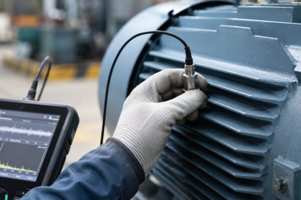
Diagnosing Misalignment with Confidence
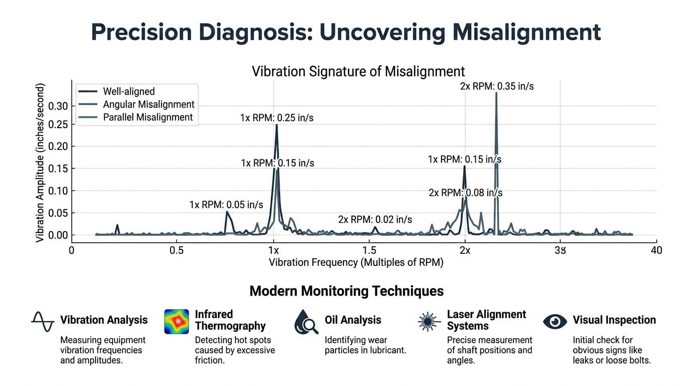
Misalignment is easy to oversimplify in diagnostics. The textbook pattern is useful, but field data rarely arrives in textbook form. Industry guidance notes that misalignment often produces strong axial vibration at 1x, 2x, and 3x running speed, but those signatures can overlap with unbalance or looseness, so confirmation requires vibration analysis plus other data such as phase and temperature (Power-MI on misalignment vibration patterns).
A refinery fin-fan cooler is a good example because the machine usually operates in a harsh environment with multiple possible faults. Fan blades can load unevenly, belts or couplings can introduce complexity, and structural looseness may exist around the motor support. If the team looks only at one spectrum and sees a strong running-speed component, they may chase balance when alignment is the more important correction.
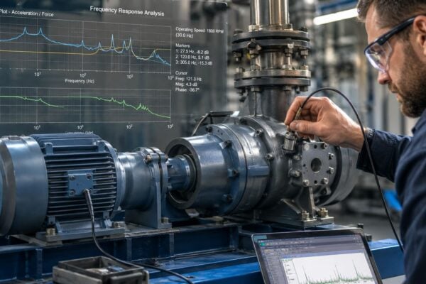
What to look for in the data
For shaft misalignment, technicians usually pay attention to these indicators:
- Axial vibration near the coupling. High axial response often points toward misalignment, especially in coupled machines.
- Running-speed harmonics. Peaks at 1x, 2x, and sometimes 3x can support the diagnosis.
- Phase behavior across bearings. Phase differences near the coupling help determine whether the machine is moving in a way consistent with misalignment.
- Temperature pattern. Localized heat around couplings, bearings, or seals can support the mechanical picture.
- Condition history. A machine that returns to the same fault pattern after replacement work often has an unresolved alignment or structural issue.
The strongest diagnosis comes from correlation, not from a single measurement. Vibration shows dynamic response. Thermography shows where friction or load may be concentrated. Oil analysis can reveal wear debris from bearings or couplings when the fault has been active long enough. Teams evaluating broader sensor strategies often review Wuxi Winteam Technology insights because mixed-fault machinery usually demands more than one data stream.
How to separate misalignment from mixed faults
A practical screening approach helps avoid false conclusions:
| Observation | More likely concern | What to check next |
|---|---|---|
| Strong 1x radial with limited axial activity | Unbalance may be dominant | Balance condition, rotor cleanliness, process buildup |
| Strong axial vibration with harmonics near coupling | Misalignment may be significant | Phase, thermal pattern, alignment history |
| Broad vibration increase with structural response | Looseness may be involved | Base bolts, soft foot, frame condition |
| Repeat seal or coupling distress after alignment | Misalignment may be secondary | Pipe strain, coupling wear, bearing fits |
A pulp-and-paper fan train often illustrates the overlap. The machine may show increased vibration after a coupling replacement. Maintenance balances the rotor, but the vibration stays. Thermography then shows one coupling end running hotter than the other, and phase data across the motor and fan bearings points to shaft relationship rather than rotor mass distribution. That sequence is common.
Field check: If the correction plan starts with balancing before anyone confirms shaft centerline, support condition, and coupling behavior, the team may be solving the wrong problem.
Once the pattern is reasonably confirmed, the next step isn't just to align the machine. It's to decide whether the machine can hold alignment after restart. That's where condition data and precision setup have to work together. Detailed motor vibration analysis practices are useful here because the motor side often carries the clearest early indicators.
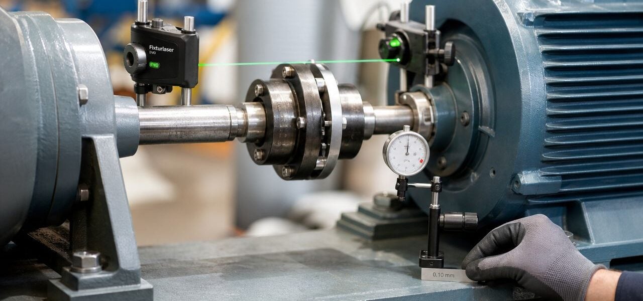
A Modern Guide to Precision Alignment and Correction
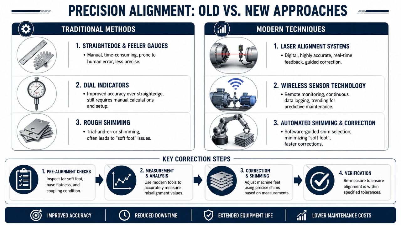
Alignment work fails when teams rush past machine stability. Expert guidance is consistent on this point. The job starts by verifying stable mounting conditions, correcting soft foot and base looseness, measuring cold alignment, compensating for thermal growth and operating load, then making controlled moves and re-measuring until the readings are repeatable. The same guidance notes that laser systems improve precision by calculating required movement and reducing technician-dependent error while shortening the job compared with dial-indicator methods (Plant Engineering on avoiding shaft misalignment).
A motor-gearbox-pump train in a water treatment plant is a good working example. It looks simple, but there are multiple interfaces, limited pipe flexibility, and little tolerance for startup surprises. If one correction introduces stress into the next machine, the entire train suffers.
Start with machine stability
Before any measurement:
- Inspect the coupling condition. A worn or damaged coupling can distort readings and hide the actual machine position.
- Correct soft foot. This isn't optional. If one foot lifts or drags the frame during tightening, the machine moves every time the bolts are touched.
- Check base integrity. Loose hold-down hardware, warped baseplates, or poor contact surfaces will destroy repeatability.
- Confirm run condition assumptions. If the machine runs hot or under high piping load, cold targets need to reflect that.
Repeatability matters because it proves the machine is mechanically stable enough to trust the numbers. If readings change on every pass, the issue isn't alignment skill. Something in the mounting or measurement setup is still moving.
Dial indicators versus laser systems
There is still a place for dial indicators, especially where teams have strong craft skill and simple machine geometry. They can work well, but they demand careful setup, manual interpretation, and more technician discipline. Errors in bracket setup, sag compensation, or move calculation can turn a straightforward job into rework.
Laser systems are usually the better choice for critical or repeat-problem assets because they:
- Reduce calculation burden
- Guide horizontal and vertical moves directly
- Improve repeatability between technicians
- Shorten outage time on multi-move corrections
That doesn't mean the tool solves every problem. If pipe strain, soft foot, or worn foundations are left uncorrected, the final numbers may still look good on screen and fail in service. A tool can't compensate for bad machine condition.
A field workflow that prevents rework
A disciplined alignment job usually follows this sequence:
- Document as-found condition. Capture the initial machine state before any shims move. This becomes the baseline for analysis later.
- Verify soft foot and stability. Correct mounting problems first.
- Take measurement passes. Use enough positions to confirm repeatability.
- Apply target values. Include compensation for expected operating movement if the machine requires it.
- Make controlled foot moves. Shim carefully, move horizontally in small steps, and tighten in sequence.
- Re-measure after each correction. The first move rarely finishes the job on a difficult asset.
- Record as-left condition. Final documentation should show the machine's achieved position and any remaining concerns.
For plants that outsource difficult alignments or need support on high-consequence assets, precision shaft alignment services from Forge Reliability are one practical option among several maintenance approaches. The main point isn't who performs the work. It's that the process must be controlled, repeatable, and tied to operating conditions rather than just shutdown geometry.
A clean final number is only credible when the machine produced it repeatedly under stable mounting conditions.
Selecting Tolerances and Verifying the Fix
Poor alignment is cited as responsible for over 50% of breakdowns in rotating machinery, which is why tolerance selection and post-job verification carry far more weight than many plants give them (Mobius conference summary on poor alignment and breakdowns). A machine doesn't need dramatic visible error to fail early. Small angular and offset deviations can keep loading seals, bearings, and couplings every time the machine turns.
A high-speed compressor in a gas processing train makes the point well. At higher speed, small geometric errors create dynamic consequences quickly. The machine may start, carry load, and still be headed toward persistent vibration, seal distress, or coupling wear if the alignment target was casual.
Why close enough fails
Tolerance isn't just a number from habit. It should come from machine speed, coupling type, OEM guidance, and the machine's expected operating position. Plants that accept "close enough" tend to create two problems at once. They leave the machine with excess load, and they erase the baseline needed for future diagnosis.
This is one reason engineering teams spend time on dimensional control in other hardware programs. The same thinking applies here. The discipline behind de-risking hardware programs with tolerancing translates directly to rotating assets. The machine only performs as intended when geometry is controlled, documented, and verified against the right limit.
Example shaft alignment tolerances
The table below is an example format for documenting short flex coupling alignment limits. Actual acceptance values should come from OEM requirements and plant standards for the specific machine.
| Operating Speed (RPM) | Acceptable Parallel Offset | Acceptable Angularity (mils/in) |
|---|---|---|
| Lower-speed equipment | Tighter than visible offset | Low angular error, documented by plant standard |
| Medium-speed equipment | More restrictive than lower-speed visual acceptance | Controlled to machine standard with repeatable readings |
| High-speed equipment | Very tight offset control | Very tight angular control with hot target consideration |
That table is intentionally qualitative because machine-specific values vary, and unsupported numbers create bad decisions. What matters is that the plant standard defines the tolerance source, not the technician's judgment in the moment.
What final verification should include
Final acceptance should answer four questions:
- Was the machine stable during measurement?
- Were target values based on operating reality, including thermal movement where applicable?
- Were final readings repeatable across multiple passes?
- Was the as-left condition stored in the maintenance system for future reference?
A machine that meets cold tolerance but misses hot target isn't fixed. A machine that meets one reading but not repeatability isn't verified. A machine with no final record can't support trend analysis through vibration monitoring practices, because the site won't know whether the next change reflects wear, movement, or a bad previous alignment.
Building a Proactive Misalignment Control Strategy
Plants that treat misalignment of shaft as a reactive repair keep paying for it in parts, labor, and interrupted production. Plants that control it as a reliability process get a different result. They build alignment checks into outage planning, condition monitoring response, installation standards, and failure analysis. That shift matters most in multi-asset facilities where pumps, motors, gearboxes, and fans share similar failure pathways.
A multi-site manufacturer with common motor-pump trains is a good example. If each site uses different alignment methods, different acceptance logic, and different documentation quality, the company can't compare asset behavior or learn from repeat failures. The work stays local and temporary.
Where alignment belongs in the maintenance system
A proactive strategy usually includes these triggers:
- After component replacement. Any motor, pump, gearbox, or coupling change should prompt alignment verification.
- After base or piping work. Mechanical disturbance often changes shaft position even when the rotating element wasn't touched.
- After abnormal condition data. Rising vibration, temperature shift, or coupling distress should trigger an alignment decision rather than a blind parts change.
- On critical-asset intervals. Some machines need scheduled checks because the process is severe enough to move them over time.
The maintenance system should also require a minimum data set in every work order. That includes as-found condition, soft foot findings, correction steps, as-left readings, and any unresolved constraints such as pipe strain or base defects. Without that record, recurring failures look unrelated when they aren't.
What standardization looks like across sites
The most effective programs standardize three things first:
- Procedure. Every team follows the same pre-checks, move sequence, and verification rules.
- Training. Technicians and planners use the same language for offset, angularity, soft foot, thermal growth, and repeatability.
- Data governance. Alignment results live inside the maintenance history, not in personal notebooks or isolated files.
That structure connects directly to broader operations and maintenance reliability support. Alignment stops being a craft task performed by a few experienced people and becomes a controlled reliability activity that any site can audit, improve, and tie to asset performance.
The plants that reduce repeat failures usually don't perform alignment more often. They perform it with better triggers, better verification, and better records.
Misalignment control works best when reliability, maintenance, and operations all own part of the result. Maintenance corrects the geometry. Reliability confirms the failure mechanism and watches the trend. Operations helps identify load, temperature, and process conditions that move the machine in service. When those groups act separately, the same machine keeps returning to the schedule.
Forge Reliability helps industrial teams build practical programs around alignment, vibration, thermography, oil analysis, and failure elimination. If recurring bearing, seal, or coupling problems are consuming maintenance time, a free reliability assessment from Forge Reliability can help identify whether misalignment, thermal growth, pipe strain, or a deeper mechanical issue is driving the repeat failures.