A conveyor bearing starts running hot on second shift. The line keeps moving because production needs the order out. By the time maintenance gets a window, the grease point is dry, the seal has cooked, and the bearing has already started shedding metal into adjacent components. The work order closes as a bearing replacement, but the underlying failure happened earlier. The lubrication system either didn't deliver grease, didn't deliver enough, or delivered it inconsistently.
That's why pneumatic grease pumps deserve more attention than they usually get. In many plants, they're treated like support hardware. In practice, they sit much closer to the root of rotating equipment reliability. A pump that cycles cleanly, maintains pressure, and feeds grease consistently protects bearings, gears, motors, and other loaded components. A pump with poor air supply, bad installation, or hidden internal wear creates chronic failure patterns that look like random machine problems.
Automated lubrication isn't new. The market for pneumatic grease pumps is growing with demand for automated lubrication in predictive maintenance programs, and early innovations go back to the 1930s with the Alemite Company's pneumatic grease guns, which laid the foundation for modern high-pressure systems integral to reliability strategies that can reduce unplanned downtime by 30% or more according to industry market analysis. Plants that care about uptime already understand the same principle in adjacent applications such as proper cutting tool lubrication. Lubrication quality changes asset life.
Maintenance leaders that want a broader plant-level view of the financial side should also look at maintenance cost reduction strategies. The costs tied to lubrication failure rarely stay inside the lube budget.
Table of Contents
- The True Cost of Lubrication Failure
- How Pneumatic Grease Pumps Work
- Selecting and Sizing Your Pump for Peak Reliability
- Installation and Centralized System Integration
- Diagnosing Common Failure Modes Like an Expert
- Preventive Maintenance and Performance Testing Procedures
- Calculating the ROI of a Reliable Lubrication Program
The True Cost of Lubrication Failure
A failed grease delivery system usually announces itself at the asset, not at the pump. In a packaging plant, that may look like a conveyor tail pulley bearing overheating. In a paper mill, it may show up as rising vibration on felt roll bearings. In a quarry, an open gear or pillow block may start consuming grease with no reduction in operating temperature because the system isn't pushing grease into the loaded zone.
The expensive part isn't just the damaged component. It's the chain reaction. Technicians get pulled into emergency work. Production loses schedule stability. Planners start expediting parts. Operators lose confidence in the equipment because the same assets keep failing for what appears to be no clear reason.
Hidden cost categories
- Secondary damage: A dry or under-lubricated bearing often damages shafts, housings, couplings, or adjacent seals before anyone isolates the original cause.
- False corrective actions: Teams replace bearings, motors, or hoses when the root cause sits upstream in the grease pump, air supply, or distribution network.
- Labor waste: Manual backfilling and emergency greasing consume skilled maintenance time that should be going into planned work.
- Data distortion: Recurrent lubrication-related failures pollute CMMS history and make RCFA harder because assets appear to have multiple unrelated failure modes.
Practical rule: If the same bearing family keeps failing across similar assets, the investigation should start with grease delivery quality before anyone blames the bearing brand or installation technique.
A food processing line offers a useful example. A set of washdown-zone conveyor bearings may fail one after another even when replacement practices are sound. The underlying problem may be that the pump can generate pressure, but the distribution layout starves the farthest points during actual operation. The result is inconsistent lubrication, not complete loss of lubrication, which is harder to catch and much more common on plant floors.
Pneumatic grease pumps matter because they move lubrication from an operator-dependent task to a controlled system. But control only helps when the pump is selected, installed, and diagnosed like a reliability-critical component.
How Pneumatic Grease Pumps Work
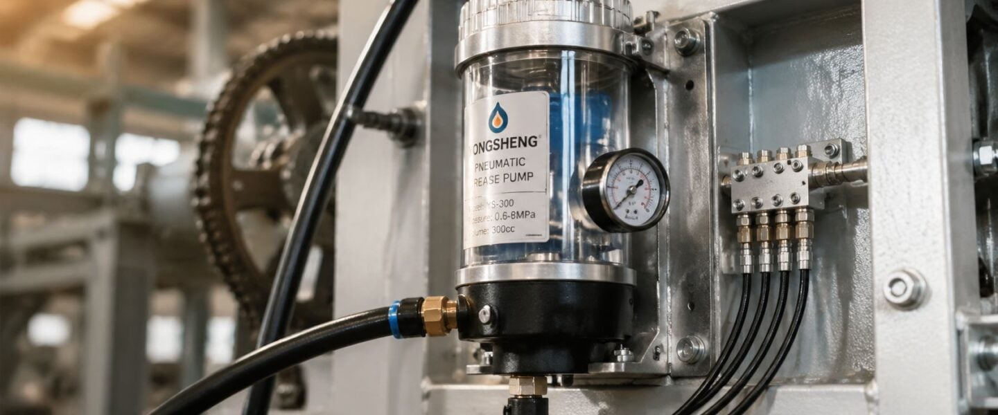
At the most basic level, pneumatic grease pumps convert shop air into grease pressure. The pump uses compressed air at 80 to 120 PSI to drive a piston, then multiplies that force through a pump ratio that typically ranges from 35:1 to 75:1, producing grease pressure up to 10,000 PSI and handling greases up to NLGI grade 2 with automatic shut-off at the set working pressure, as described in this technical explanation of pneumatic grease pump operation. For engineers managing centralized lube hardware, this matters because the pump isn't just moving grease. It's overcoming line resistance, fitting resistance, and grease consistency.
A useful way to think about it is a hydraulic jack in reverse motion. A modest input force acts over one area, then the mechanical arrangement concentrates that force into a much higher output pressure at the grease side. The air motor provides the motion. The pump tube turns that motion into suction and discharge.
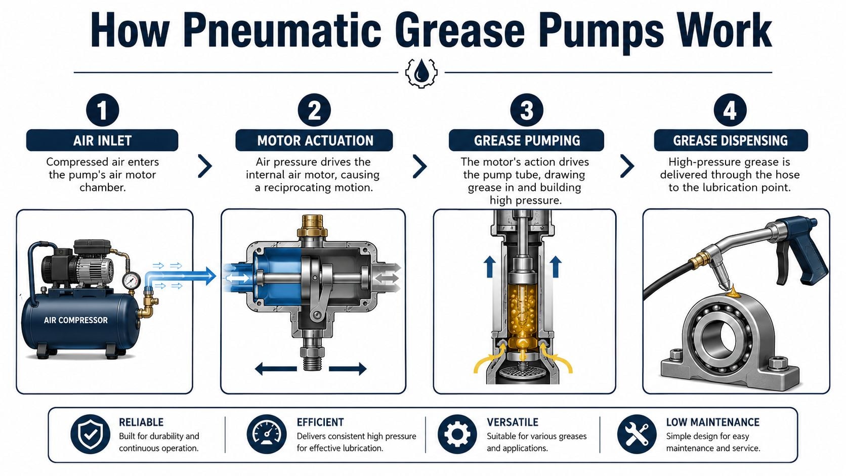
Pressure multiplication in plant terms
A pump ratio is the relationship between input air pressure and output grease pressure. Higher ratios let the pump push grease through long lines, restrictive fittings, or stiff grease, but they also increase the system's sensitivity to air quality and internal seal condition.
For a plant engineer, ratio selection is practical, not theoretical.
- A lower ratio may work well for short runs and easy-flowing grease.
- A higher ratio becomes necessary when the system must push grease through more resistance.
- Excess ratio can mask underlying restriction problems for a while, then accelerate wear elsewhere.
An engineer reviewing lubrication system design considerations should connect pump ratio to actual system resistance, not just barrel size or hose length.
The parts that actually matter in failure analysis
Two subassemblies do most of the work.
The air motor converts compressed air into reciprocating motion. If it receives unstable air pressure, wet air, or contaminated air, the motion becomes erratic or stalls.
The pump tube contains the grease-handling components. It draws grease in during suction, then pressurizes and discharges it on the return stroke.
Within those assemblies, a few components deserve special attention:
- Reciprocating piston: The moving element that creates the pumping action.
- Check valves: One-way valves that let grease enter and exit in sequence. If they leak internally, the pump may cycle without building effective output.
- Follower plate: A plate that maintains contact with the grease in the drum. Its job is to prevent air entrainment and support steady suction.
- Seals: These maintain pressure separation. Once they wear, the pump may still move but lose force.
A pump that cycles isn't automatically a pump that lubricates. Motion confirms activity. It doesn't confirm delivery.
A steel mill example makes this clear. A pump feeding motor bearings on a dust-prone line may sound healthy and stroke normally, yet still fail to deliver usable grease because the follower plate has admitted air or a check valve no longer seats properly. The operator hears cycling. The bearing sees starvation.
Selecting and Sizing Your Pump for Peak Reliability
The wrong pump usually fails in one of two ways. It's undersized and can't maintain delivery under real system resistance, or it's oversized and hides layout problems while wasting air and stressing components. Reliable selection starts with the lube point, not the drum package.
A paper machine felt roll circuit is a good example. Those bearings often sit in a wet, contaminated environment and still need consistent grease movement through a fixed routing path. If the selection only focuses on “high pressure” as a buying criterion, the pump may be installed with enough theoretical capability but poor fit for line resistance, grease consistency, and duty pattern.
Start with the application, not the catalog
Three decisions drive reliability.
First, define the grease consistency. Pneumatic grease pumps can handle greases through NLGI grade 2, but that doesn't mean every ratio works equally well in every layout. Stiffer grease raises the margin for error on long runs, cold areas, and small-diameter distribution lines.
Second, define the delivery path. A pump feeding a nearby bearing bank behaves differently from a pump feeding multiple points across a long conveyor or a paper machine frame. More branches mean more opportunities for pressure imbalance, trapped air, and uneven feed.
Third, define the lubrication objective. Some applications need frequent small shots to maintain a grease film. Others need higher resistance capability to push fresh grease into loaded interfaces that don't purge easily.
A selection review should answer these questions:
- What resistance must the pump overcome: This includes grease consistency, line routing, and point accessibility.
- How many lube points share the pump: More points usually mean greater sensitivity to balance and priming quality.
- What environment surrounds the hardware: Moisture, washdown, dust, and corrosive exposure all affect material choices and maintenance intervals.
- What happens if the pump underperforms: A lightly loaded idler and a critical process bearing don't deserve the same risk tolerance.
Pump Ratio Selection Guide by Application
| Pump Ratio | Typical Output Pressure (PSI) | Grease NLGI Grade | Common Applications |
|---|---|---|---|
| 35:1 | Lower end of high-pressure delivery | 0 to 1 | Short distribution runs, accessible points, lighter centralized systems |
| 50:1 | Mid-range high-pressure delivery | 0 to 2 | General plant lubrication, conveyor bearings, motor and gearbox support points |
| 75:1 | Upper end, up to 10,000 PSI depending on input air pressure | 1 to 2 | Long lines, higher resistance circuits, stiff grease service, heavy industrial points |
The table reflects the verified operating range discussed earlier, where output depends on air pressure and ratio within the documented 35:1 to 75:1 range and can reach 10,000 PSI under suitable conditions.
Selection should leave operating margin, but not so much margin that the pump becomes a substitute for good distribution design.
A cement handling conveyor illustrates the trade-off. If the farthest tail pulley and take-up bearings receive grease through long routed lines, a higher-ratio pump may be justified. But if the installation still uses poor line routing, dead legs, or uneven branch lengths, increasing ratio won't fix the root problem. It only postpones it.
For many plants, the most effective sizing review comes during an equipment condition assessment for lubrication systems, where the pump, air supply, and lube points are evaluated together instead of as separate purchases.
Installation and Centralized System Integration
A well-selected pump can still perform badly after a weak installation. Most recurring field problems trace back to the interfaces around the pump. Air line routing, filtration, drum setup, and branch layout often matter more than the nameplate.
An automotive conveyor network shows this clearly. A new pump may be installed to serve several lubrication zones without changing the old branch arrangement. The pump is blamed when flow becomes inconsistent, even though the actual issue is uneven downstream resistance and poor air-side support.
Air side mistakes that create grease side failures
The pump only works as well as the compressed air feeding it. A line that looks acceptable at rest may collapse under cycling demand. That's why installation reviews should include air supply behavior during actual operation, not just a static pressure reading.
Three mistakes show up repeatedly:
- Undersized air lines: Small line size creates avoidable pressure loss during demand changes.
- Long air runs without adjustment: Friction losses accumulate, especially when routing is added after the original install.
- Poor moisture control: Water and contamination shorten component life and create erratic operation.
A proper FRL setup matters because it conditions the air before it reaches the motor section. The filter removes contamination, the regulator stabilizes supply pressure, and the lubricator function applies only where the pump design calls for it. Blindly adding components without checking pump requirements creates its own problems.
Integration choices that affect system stability
On the grease side, centralized systems need balanced routing and clean suction conditions. A follower plate installed poorly can admit air into the grease column. Once air enters, the pump may cycle but produce spongy output, delayed pressure build, or intermittent starvation at remote points.
Good integration practice usually includes:
- Stable drum engagement: The suction path must stay fully immersed and sealed.
- Logical branch routing: Avoid unnecessary elevation changes, long unsupported loops, and abrupt path differences between similar points.
- Accessible isolation points: Technicians need places to test sections without dismantling the full network.
- Clear maintenance records: If zones are changed, the documentation has to change with them.
A centralized lubrication network becomes far easier to manage when changes are tracked inside a CMMS implementation for lubrication systems. Without that discipline, technicians inherit a field-built system no one fully understands, and diagnosis slows down every time a point stops receiving grease.
Diagnosing Common Failure Modes Like an Expert
Most technicians can troubleshoot a dead pump. The harder job is diagnosing a pump that still appears active. Root cause failure analysis starts with the symptom at the lube point, then works backward through the pump, the air supply, and the distribution path.
One hard threshold matters on the air side. A static-to-dynamic pressure drop greater than 15 PSI indicates insufficient compressed air volume or restrictive line sizing, and most pumps need at least 3/8 inch air line sizing, increasing to 1/2 inch for air runs over 50 feet. Another specific failure mode worth checking is water in the air supply port, which degrades internal parts and has been identified in failures involving the Fireball 425 component family in this air grease pump troubleshooting guidance.
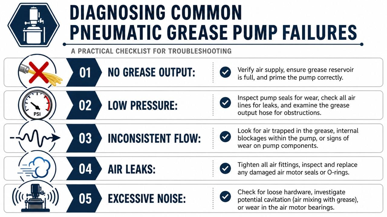
When the pump runs but the point stays dry
This symptom causes a lot of wasted parts replacement because the pump sounds alive.
Probable root causes include:
- Loss of prime: Air has entered the suction side, often through follower plate issues or drum changeover mistakes.
- Blocked outlet path: Grease can't move past a restriction in the hose, injector, or fitting.
- Internal check valve leakage: The piston cycles, but pressure bleeds back internally instead of reaching the lube point.
A practical diagnostic sequence is simple. First confirm the drum has grease and the suction side is sealed. Then isolate the outlet as close to the pump as possible to determine whether the problem lives inside the pump or downstream in the distribution network. If output is present at the pump but absent at the point, the problem is almost never “low grease” by itself. It's path resistance, trapped air, or blockage.
When pressure is low or unstable
Erratic pressure is where technicians need to stop guessing. A static gauge reading at the regulator isn't enough. The useful check is pressure during pump cycling.
Use this sequence on the plant floor:
- Measure supply pressure with the pump idle.
- Measure again while the pump is cycling under normal load.
- Compare the readings.
- If the drop exceeds the verified threshold noted above, investigate line size, line length, compressor capacity, and restrictions upstream.
After the air side is verified, inspect for external leaks and then move to internal wear suspects. Low or unstable pressure often traces to sealing surfaces or valve seating problems. In a multi-point conveyor system, branch imbalance can produce the same symptom at the asset level even when the pump itself is healthy.
Don't diagnose pressure problems from the regulator alone. Diagnose them under flow.
When seals fail early
Premature seal failure rarely comes from “bad luck.” It usually points to a heat, contamination, or overwork problem. Water in the air supply port is a specific red flag because it attacks internal components and accelerates wear. If moisture is found there, the investigation should include filtration effectiveness, condensate management, and line routing that promotes water carryover.
A mining or bulk handling application provides a typical example. Pumps installed near outdoor doors or unconditioned utility corridors often see more condensation. Technicians replace seals, restore function briefly, then watch the same failure return because no one corrected the air quality issue.
A strong RCFA write-up for pneumatic grease pumps should include:
- Observed symptom: No output, low pressure, stall, or rapid wear
- Failed component: Seal, valve, fitting, hose, or air motor part
- Contributing condition: Moisture, undersized air line, blocked branch, poor follower plate setup
- Verification test: Dynamic pressure check, isolation test, moisture inspection, or line clearing
- Permanent corrective action: Design or maintenance change, not just part replacement
That approach turns lubrication from repetitive firefighting into a managed reliability process.
Preventive Maintenance and Performance Testing Procedures
Preventive maintenance on pneumatic grease pumps shouldn't be limited to “check for leaks.” A useful PM routine verifies that the pump can still deliver grease under demand and that the conditions causing wear are controlled before output collapses.
One temperature limit deserves strict enforcement. During operation, bearing temperature must not exceed 35°C above ambient and must never exceed an absolute 80°C, because higher temperature can degrade the polyurethane oil seal, which is a primary failure point and may require replacement to prevent oil delivery blockage according to this pneumatic grease pump maintenance reference.
A technician-level maintenance view is shown below.
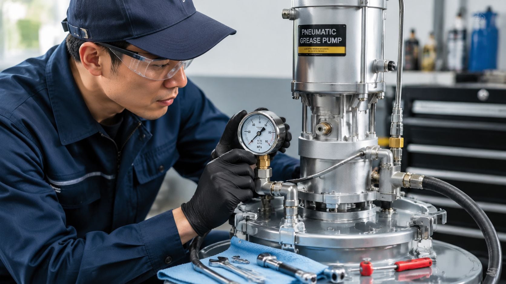
A practical PM routine
A workable schedule focuses on condition, not just calendar tasks.
- Visual inspection: Check for grease leaks, air leaks, damaged hoses, loose fittings, and poor drum seating.
- Air quality check: Drain moisture sources where applicable and inspect upstream filtration condition.
- Follower plate condition: Confirm smooth travel and proper contact with the grease surface.
- Temperature review: Any abnormal heat at the pump bearing area needs immediate attention because seal life drops quickly once the thermal limit is exceeded.
In a beverage facility with frequent washdown, this routine matters even more because moisture migration and contamination don't stay localized. A pump that looks clean outside can still be ingesting harmful air quality through the supply side.
Performance tests that catch wear early
Two test concepts are especially useful.
The first is a stalled pressure check. The purpose is to confirm that the pump still develops the pressure expected for its configuration and that it holds pressure without obvious internal bypass. If the pump can't build or sustain pressure during the test, internal wear or leakage is likely.
The second is a timed output check. This is less about a universal target and more about trend consistency. If output over a fixed test interval drops from the pump's established baseline, something has changed. Common causes include suction problems, internal wear, or increasing restriction.
A strong PM record should document:
- Observed cycle behavior: Smooth, erratic, or delayed
- Leak status: None, air side, grease side, or both
- Temperature status: Within limit or shutdown required
- Output trend: Stable, declining, or inconsistent
- Corrective trigger: Rebuild, seal replacement, line inspection, or air-side repair
Planners building a sustainable program should tie these checks into a broader preventive maintenance strategy for lubrication systems. That's how recurring pump problems stop repeating across shifts.
Calculating the ROI of a Reliable Lubrication Program
The business case for pneumatic grease pumps isn't about buying a pump. It's about preventing a chain of losses that starts with poor lubrication delivery and ends in avoidable downtime, scrap risk, expedited labor, and repeated parts consumption.
A useful ROI review starts with total cost of ownership. The initial purchase is only one line item. The more important questions are operational. How often do technicians respond to repeat lubrication complaints? How many bearing replacements were delivery failures? How much production risk sits on assets fed by a weak centralized system?
A practical TCO framework should include:
- Direct maintenance cost: Pump rebuild kits, hoses, fittings, seals, and labor
- Asset repair cost: Bearings, shafts, housings, and adjacent components damaged after lubrication failure
- Downtime exposure: Lost production windows, delayed orders, and startup instability after emergency work
- Program efficiency: Reduction in manual greasing rounds, fewer repeat work orders, and better planning accuracy
The strongest savings often come from failure avoidance, not labor reduction. A pump that is correctly selected, properly installed, and routinely tested gives maintenance teams confidence that grease is reaching the point of use. That confidence changes planning behavior. Teams stop over-lubricating as insurance. They stop replacing healthy components to solve delivery problems. They stop treating recurring bearing failures as isolated events.
For plant operations leaders, the decision is straightforward. If lubrication failure repeatedly appears in bearing, gearbox, and motor histories, the pump system deserves a formal reliability review. That review should examine the pump, air supply, line design, PM routine, and RCFA history as one system.
Plants that want to reduce lubrication-related failures can start with a no-cost review from Forge Reliability. A free reliability assessment can identify weak points in pneumatic grease pumps, centralized lubrication circuits, PM routines, and failure analysis practices before the next dry bearing turns into unplanned downtime.