
A pneumatic cylinder drops out of detection, the reject arm fires late, and a good product slips past the checkweigher. On the floor, the sensor looks innocent enough, but the line still slows, the operator calls maintenance, and everyone starts asking whether the issue is the magnet, the bracket, the cable, or the logic in the PLC. That's the reality of a magnetic proximity sensor in production, it's a small device with a very real say in uptime, quality, and safety.
Plant teams don't need another physics lecture. They need a practical way to choose the right sensing principle, mount it so it stays stable, and diagnose the failures that happen on conveyors, pumps, guard doors, and robotic cells. They also need to treat the sensor as a reliability asset, not a commodity part that only gets attention after a false trip shuts a line down.
Table of Contents
- When a Magnetic Proximity Sensor Stops a Line
- How a Magnetic Proximity Sensor Works
- Comparing Reed, Hall-Effect, and Magnetoresistive Designs
- Selecting a Magnetic Proximity Sensor for Industrial Duty
- Mounting, Wiring, and Shielding Best Practices
- Common Failure Modes and How to Diagnose Them
- Folding Magnetic Proximity Sensors Into a Predictive Maintenance Program
When a Magnetic Proximity Sensor Stops a Line
A missed signal on a food and beverage conveyor is rarely dramatic at first. A reject arm fires a little late, a diverter misses the window, or a fill station keeps running when the guard should have locked out. By the time quality finds the escape, the root cause may be a magnetic target that drifted, a cable that flexed itself open, or a sensor mounted so close to steel that its assured switching distance collapsed.
That failure pattern matters more than the device label. A magnetic proximity sensor is a control point that tells the PLC when a cylinder is home, a gate is closed, or a pump housing is in position. If that point is unreliable, the line absorbs nuisance stops, false interlocks, and extra troubleshooting time that chips away at availability.
Practical rule: treat every proximity point as part of the machine's operating state, not as a standalone electrical accessory.
The first industrial-grade inductive proximity sensor was launched in 1958 to replace mechanical switching contacts and reduce break sparks and explosion hazards in chemical plants, with an intrinsically safe design aligned to NAMUR Pepperl+Fuchs' historical account. That history still fits the work on the floor. The job is the same, replace contact wear and unstable switching with a non-contact device that can survive vibration, washdown, bracket flex, and maintenance handling.
By the end of the 1980s, Pepperl+Fuchs reported almost 4 million proximity sensors sold in Germany alone, which shows how quickly a niche safety idea became mainstream automation hardware. Volume does not remove the reliability burden. It raises it, because more installed points create more chances for misalignment, bad routing, and inconsistent setup.
The question is not, “Does the sensor detect a magnet?” The questions are, “Will it keep detecting it under vibration, washdown, bracket flex, EMI, and maintenance mistakes?” and “Can it be folded into the plant's PdM and RCM work, instead of being replaced on instinct?”
Forge Reliability's OEE improvement perspective fits that mindset because these small devices often decide whether a line runs cleanly or limps through repeated micro-stops.
How a Magnetic Proximity Sensor Works
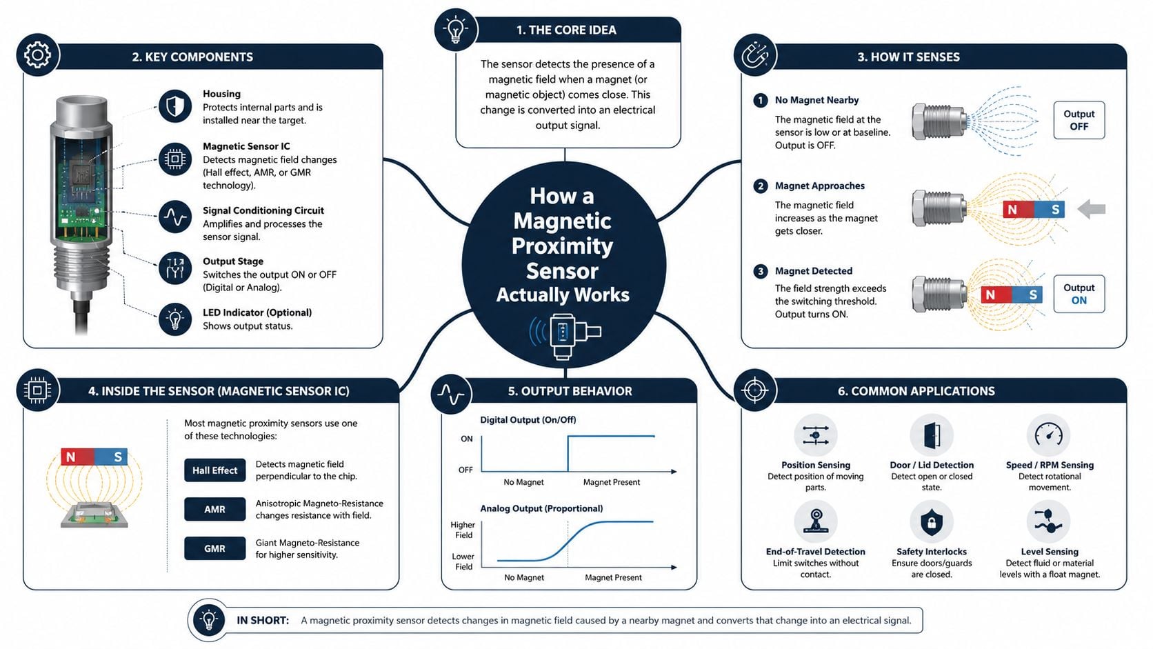
A magnetic-field detector changes its output when a magnetized target comes close enough. In plant terms, it turns invisible motion into a clean electrical signal the control system can use. The target might be a magnet on a cylinder, a magnetized fastener, or a moving assembly carrying a magnetic element.
Three sensing principles matter
A reed switch is the simplest version. It uses two metal reeds sealed in glass, and a magnetic field pulls them together like a magnetic snap-action contact. It is simple and quiet, but the moving contact means electrical life is tied to mechanical life.
A Hall-effect device is a semiconductor sensor that produces a voltage proportional to magnetic field strength, almost like a magnetic fuel gauge. There is no contact bounce, no reed flexing, and no glass capsule to fatigue. That makes it a solid fit for general presence detection and control signals.
A magnetoresistive element changes resistance when a magnetic field acts on it, which is why it behaves more like a magnetic strain gauge. The family includes AMR (anisotropic magnetoresistance), GMR (giant magnetoresistance), and TMR (tunneling magnetoresistance). Sensitive magnetic detection moved from physics work into factory use once the technology matured, and that matters on the plant floor because these parts can pick up weaker fields and tighter position changes than simpler sensors Trinity College Dublin's magnetism research material.
Why the physics changes reliability work
The sensing principle decides what fails first. Reed switches can wear mechanically over time, Hall-effect parts are usually about stable switching and clean wiring, and magnetoresistive devices reward precision but punish sloppy installation more quickly. In a robotic cell, that difference shows up fast, one sensor shrugs off vibration while another starts flirting with nuisance trips because the magnetic environment is not controlled.
That is why experienced maintenance teams care less about the textbook and more about the duty cycle, the mounting method, and how much magnetic noise surrounds the target. The same device can look perfect on paper and still miss a position if the bracket, magnet orientation, or surrounding steel changes the field shape.
Comparing Reed, Hall-Effect, and Magnetoresistive Designs
The choice usually comes down to cycle rate, field strength, and tolerance for installation slop. Each technology has a place, but none of them wins everywhere.
| Criterion | Reed switch | Hall-effect | Magnetoresistive (AMR/GMR/TMR) |
|---|---|---|---|
| Switching speed | Best for low-cycle duty | Good for general automation | Best for faster or more precise sensing |
| Electrical life | Limited by contact action | Strong, solid-state | Strong, solid-state |
| Sensitivity | Moderate | Moderate | High, often much higher than Hall |
| Robustness to vibration | Good when sealed and lightly cycled | Good | Good, but installation-sensitive |
| Contamination tolerance | Good in sealed use | Good | Good, but depends on magnetic layout |
| Temperature tolerance | Application dependent | Application dependent | Application dependent |
| Current capability | Often simple, low-power | Broad industrial use | Broad industrial use |
| Typical duty | Basic interlocks, low duty counters | Presence detection, general control | Weak-field, longer-range, precise position work |
What each one does best
A reed switch still earns its keep in low-cycle, hermetically sealed interlock duty. It's simple, it consumes little to no standby power, and it can be the right answer for a cabinet door, a basic guard, or another point that doesn't switch constantly. In a quiet environment, that simplicity is hard to beat.
Hall-effect devices dominate general-purpose presence detection because they're solid-state and predictable. That makes them a strong fit for packaging lines, conveyor stops, and many cylinder-home applications where the target is consistent and the environment is not excessively magnetic.
Magnetoresistive parts are the premium choice when the sensor has to see weak fields, longer distances, or finer position detail. The trade-off is that higher sensitivity can become a liability in dense automation cells, where nearby magnets, solenoids, and motors create cross-talk. As Baumer notes in its technical material, magnetoresistive sensors are highly sensitive and the application becomes more dependent on magnetic environment control Baumer's magnetic proximity sensor overview.
A newer sensing principle isn't automatically the better reliability choice. The right device is the one that matches target geometry, cycle rate, and the magnetic clutter around it.
For a conveyor position check, Hall-effect is often enough. For a weak magnet behind a bracket or a tighter position window on a motion axis, magnetoresistive detection can solve the problem, but only if the installation is disciplined.
Selecting a Magnetic Proximity Sensor for Industrial Duty
A sensor can pass bench tests and still fail on the floor. The spec sheet only helps if you read it against the machine's real motion, the cleaning cycle, and the way maintenance crews will wire and replace the device.
Read the specification like a maintenance person
One industrial Hall-effect style sensor family operates from 10 to 30 V DC, includes reverse-polarity, short-circuit, and overload protection, and is rated IP67 for harsh or washdown environments industrial Hall-effect style sensor family. That combination matters because field failures usually come from wiring faults, moisture, or contamination at the installation point, not from the sensing principle by itself. A cylindrical magnetic DC sensor series is listed with a 5 kHz switching frequency, 10 to 30 VDC supply, <10 mA no-load current, <2.5 V voltage drop, and 1 to 10% repeat accuracy depending on nominal distance cylindrical magnetic DC sensor series.
Those numbers drive the selection. A 20 Hz part is fine for confirming a guard is closed or a fixture is seated, but it is the wrong choice for high-speed indexing or pulse counting. A 5 kHz part belongs in fast motion feedback or cycle-counting duties where a missed transition would hide a developing problem.
Use the target, not the part number, to drive the choice
A centrifugal pump on a chemical line is a good example. If the magnetic sensor is confirming bearing-housing position, the bracket material, washdown exposure, and the magnet's real travel path matter more than the catalog headline. If the sensor sits behind magnetizable steel, the guaranteed switching range under worst-case alignment is the number to engineer to, not the nominal maximum printed in the brochure.
Engineering habit: size to the worst credible mounting condition, not the prettiest test bench result.
The same logic applies to output style. PNP vs NPN, NO vs NC, and analog versus discrete output are wiring decisions, and they determine how the PLC interprets a failed signal and whether the circuit behaves safely when a wire opens. A poor fit here can turn a simple sensor issue into a control-system headache.
Forge Reliability's condition monitoring approach belongs in this conversation because sensor selection improves when it is tied to criticality, failure consequence, and data use instead of purchase price alone.
Mounting, Wiring, and Shielding Best Practices
Most magnetic proximity sensor failures are installed, not designed. A good sensor mounted badly will still create nuisance trips, and a modest sensor mounted correctly often outlasts the expensive one that was rushed into the wrong bracket.
The bracket is part of the sensor system
Flush mounting can be useful when the machine needs a protected face, but it also changes the magnetic field around the sensor. Non-flush mounting gives more freedom, yet it can leave the sensing face vulnerable to impact. With magnetoresistive parts, ferromagnetic brackets can shrink the assured switching distance even when the nominal range looks generous on the datasheet, which is why the metal around the sensor has to be treated as part of the circuit, not just the support structure.
On a robotic cell guard-door interlock, a tiny change in bracket material can shift the field enough to create intermittent trips. The fix is usually boring, which is a good thing, better alignment, a different standoff, or a target magnet placed where the field remains consistent through the full travel.
Wiring discipline prevents phantom faults
Sensor cable should stay away from VFD outputs, motor leads, and other noisy conductors. Shielded cable helps, but only if the shield termination and grounding are done correctly and consistently. Sharp bends near vibration sources invite fatigue at the gland, and a missing service loop can turn a minor tug into a broken conductor.
A few field habits save time later.
- Label both ends: Maintenance should be able to trace a sensor cable without guessing.
- Use strain relief: A connector or gland that grips the cable reduces flex damage.
- Separate power and signal routes: Cross noisy cables at right angles when they must cross.
- Inspect after tightening: Cable glands can look fine and still pinch conductors if over-torqued.
The right acceptance test happens after installation, not just on the commissioning sheet. A switch that looks fine in a dry run can fail once the machine vibrates, a washdown starts, or the cable bundle settles into its final position.
If the machine is tied to supervisory logic, the control view should reflect that physical reality. A practical commissioning workflow often starts with the sensor point, then checks how the PLC and SCADA layer respond to the signal path, especially on complex cells PLC and SCADA integration guidance.
Common Failure Modes and How to Diagnose Them
A good troubleshooting sequence starts with the symptom, not the assumption. When a magnetic proximity sensor misbehaves, the fastest win is usually to ask whether the fault lives in the sensor, the target, the wiring, or the magnetic environment.
Five failure modes show up again and again
Moisture or contamination ingress is the first suspect on washdown equipment. If the enclosure rating is wrong, or the cable gland is loose, water and residue can create intermittent behavior that looks electronic but is really environmental. The cure is to confirm the rating, inspect the gland, and look for residue on the sensing face before replacing the device.
Wiring faults come next. Reverse polarity, broken conductors at the flex point, and poor grounding can all create dead signals or unstable ones. One industrial Hall-effect family explicitly includes reverse-polarity, short-circuit, and overload protection industrial Hall-effect style sensor family, which helps, but it doesn't remove the need for a meter check and a tug test on the cable.
Target misalignment or weak magnets often hides behind “sensor failure” complaints. A magnet can be damaged, flipped, or replaced with a non-ferromagnetic fastener during maintenance. A quick visual inspection, plus verification of the target's position relative to the sensing face, usually exposes the problem.
External magnetic interference and cross-talk are getting more common as plants pack more actuators into smaller cells. Nearby solenoids, motors, and adjacent sensors can distort the field, especially when magnetoresistive devices are used close together. If the signal becomes suspicious, move the sensor to a known-good location or temporarily isolate nearby magnetic sources.
Mechanical fatigue of reed switches shows up on high-cycle duty. The symptom is often a contact that works on the bench but gets flaky in service. In that case, the diagnosis is less about the PLC and more about whether the application should have been assigned to a solid-state device from the start.
If the same point keeps failing, the root cause usually sits in the installation standard, not in the last sensor box that got swapped.
A technician trying to separate signal issues from hydraulic or pneumatic problems can borrow the same disciplined approach used to diagnose hydraulic system faults, start with symptoms, isolate the moving target, then verify the control signal before blaming the component. Recurring trips belong in a root cause failure analysis loop, not in a pile of replaced parts Forge Reliability's root cause failure analysis approach.
Folding Magnetic Proximity Sensors Into a Predictive Maintenance Program
A magnetic proximity sensor becomes much more valuable when it stops acting like a simple switch and starts acting like a data point. In an FMEA or RCM program, it can verify position, count cycles, confirm safety interlocks, and timestamp events inside the maintenance record. That gives the plant a cleaner picture of what the machine did, not just what the operator thought it did.
Use the signal alongside condition monitoring, not instead of it
Vibration analysis, oil analysis, thermography, ultrasound, and motor current signature analysis each answer a different question. Those methods characterize asset health on pumps, compressors, motors, gearboxes, VFDs, and turbines. A magnetic proximity sensor answers a different question, whether the asset was in the right state at the right time.
That distinction matters on a chemical plant pump discharge valve. If cycle counts from the magnetic sensor drift upward while vibration starts to change, the maintenance team gets an earlier warning that a mechanical issue is building. The sensor doesn't replace vibration data, it gives context to it.

Sensor density changes the reliability problem
Plants are adding more sensors in tighter spaces, which increases the need for layout rules, shielding reviews, and acceptance testing. That's where cross-talk, false trips, and mounting sensitivity show up first. A crowded cell with multiple magnets deserves the same discipline as any other critical system, criticality ranking, installation standards, and periodic verification.
A practical reliability assessment should map every magnetic proximity sensor to the asset it protects, the consequence of a miss, and the quality of its mounting and wiring. If the plant is already seeing flicker, nuisance trips, or unexplained interlock drops, it helps to pair that review with a broader electrical troubleshooting mindset, including resources such as diagnosing flickering lights and tripping circuits, because control power and signal integrity often fail for related reasons.
Forge Reliability's predictive maintenance for manufacturing fits here because the best programs don't treat sensors as isolated parts. They treat them as evidence, inputs to failure analysis, and practical guardrails that help the maintenance team stop chasing symptoms.
Forge Reliability helps plants turn small sensing problems into clear reliability wins, from magnetic proximity sensor selection to installation review, fault isolation, and PdM integration. If recurring trips, missed counts, or guard-interlock issues are slowing your line, visit Forge Reliability to request a free reliability assessment and see where better sensor discipline can reduce unplanned downtime.