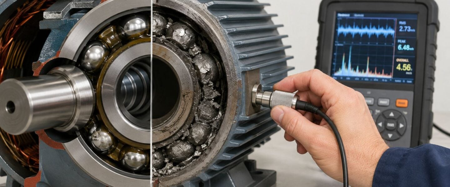
Bearing failure shows up in motor fleets far more often than many plants want to admit. Across major reliability surveys, bearings were the leading failure mode, including 44% of failures in the IEEE-IAS industrial survey and 41% in the EPRI utility survey, with overall failure rates clustering around 3 to 7 failures per 100 motor-years source. That's why electric motor bearing failure is not a nuisance problem on the edge of the program, it's the center of it.
In practice, that means most plants don't have a “rare bearing issue.” They have a recurring reliability problem that keeps reappearing under different labels, vibration alarms, overheating, grease changes, or repeat replacements. Plants with tighter maintenance intervals also tend to hold the line better, because the historical survey data shows a lower failure rate when maintenance discipline is stronger source. A wastewater line, a compressor train, or a conveyor drive can all lose availability the same way, one bearing at a time.
The right response isn't to treat every failed bearing as random wear. It's to identify the mechanism, prove the root cause, and correct the operating condition that destroyed the last bearing. That's the difference between endless swap-outs and durable reliability.
Table of Contents
- Why Bearing Failure Dominates Motor Downtime
- The Four Primary Bearing Failure Mechanisms
- Diagnostic Techniques for Detecting Bearing Defects
- Separating Electrical Damage from Lubrication Failures
- Stepwise Diagnostic Workflow for Motor Bearing Problems
- Building a Reliability Program Around Bearing Health
- Real-World Application and Next Steps
Why Bearing Failure Dominates Motor Downtime
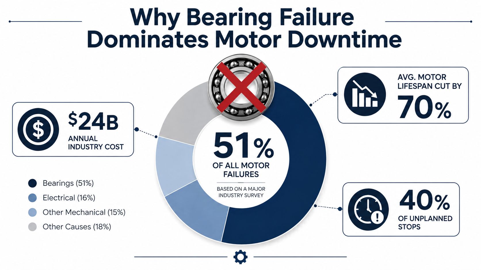
Bearing failures dominate motor downtime because they sit behind a large share of repeat outages and the failure pattern is often slow enough to be missed until the machine is already out of service. Survey work has pointed to the same basic conclusion for years, bearing failure remains the dominant failure mode in electric motors source. An ABB-based summary reports 51% of failures are bearing related, and another industry review places bearings at 40% to 50% of motor failures source. That is why the topic stays on the maintenance agenda instead of fading into the background.
The operational meaning of the numbers
A bearing issue turns into a production issue fast because it usually does not present as a clean electrical trip. The first signs are often subtle, a little extra heat, a tone change, or a vibration pattern that gets overlooked until the next outage window is already gone. Once the bearing surface starts to break down, the machine begins reacting to the friction, looseness, and imbalance that follow.
Practical rule: if a motor keeps failing at the same position, the bearing system deserves root-cause review before the next replacement is ordered.
The maintenance interval data in the ABB summary is useful because it links program discipline to outcome. Plants with maintenance intervals under 12 months showed a failure rate of 0.0124 FPU, while intervals of 13 to 24 months rose to 0.0506 FPU, and intervals greater than 25 months reached 0.0881 FPU source. That does not mean calendar maintenance by itself solves bearing problems, but it does show how drift, deferment, and weak follow-through raise exposure.
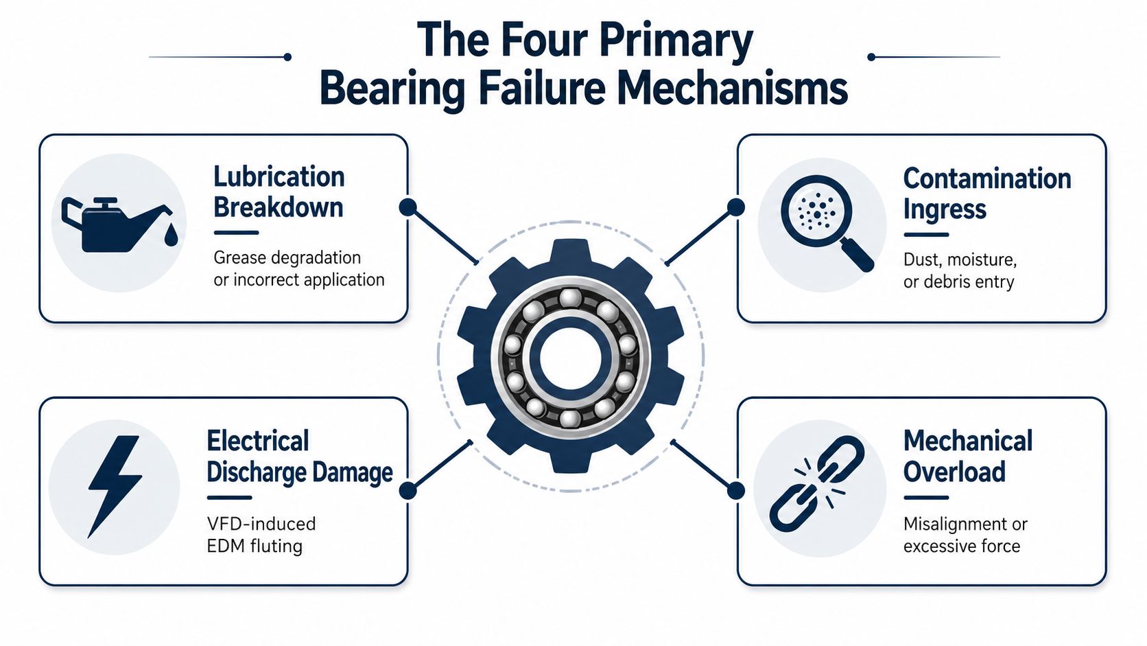
The diagnostic challenge is separating failure paths that look similar on the outside. A bearing damaged by poor lubrication does not require the same fix as a bearing pitted by VFD-induced electrical discharge, and contamination points to a different operating problem again. A useful starting point is a structured motor testing and monitoring workflow, like the one outlined in electric motor maintenance testing and monitoring practices, because the decision has to be made from evidence, not from the last part number pulled from stock.
For a reliability engineer, the lesson is straightforward. Bearings dominate downtime because they sit at the intersection of lubrication, contamination, loading, alignment, and electrical stress. That creates one component with several failure pathways, which is exactly why it needs a structured diagnostic method instead of a generic replace-and-hope response.
The Four Primary Bearing Failure Mechanisms
Every failed motor bearing leaves a surface story. Some failures start with a lubricant film that breaks down. Others begin when dirt or water gets where it does not belong. In VFD-driven motors, the failure may begin with electrical discharge damage instead of a mechanical problem. Mechanical overload and misalignment create a fourth path, and in the field, these mechanisms can overlap.
Lubrication breakdown and contamination ingress
Lubrication failure is widely identified as the leading cause of bearing failure in electric motors, and the physics are straightforward. Too little grease strips away the elastohydrodynamic film, so rolling elements and raceways begin touching metal to metal. That contact raises heat and accelerates surface fatigue. Too much grease causes its own damage, because it increases friction, pushes against seals, and can overheat the bearing.
Contamination works differently, but the end result is similar. Particles about the thickness of the lubricant film, roughly 0.5 microns, can start surface damage that progresses to spalling source. Clean handling, correct grease selection, and controlled relubrication matter more than adding grease more often. When the lubrication path is wrong, more grease usually makes the problem worse.
A bearing can survive a lot of load abuse for a while. It will not survive bad grease or dirty grease for long.
Electrical discharge and mechanical overload
Electrical discharge damage shows up in VFD-fed motors when shaft voltages pass through the lubricant film and create EDM-like pitting on the raceways and rolling elements. ABB notes that these bearing currents can drive failures within months, even where bearings might otherwise be expected to last five years or more source. The visual signature often includes fluting, corrugation, and pitted surfaces.
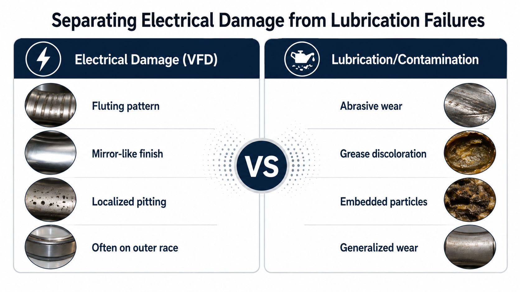
The diagnostic split matters here. Electrical damage often leaves a patterned raceway signature, while lubrication and contamination failures usually show smear, discoloration, or random surface distress. A bearing under excess load can still look similar at first glance, so the load path has to be checked before the root cause is assigned. That is why a review of radial and axial load behavior belongs in the diagnosis, especially on machines where thrust or belt load changes the contact pattern.
Mechanical overload and misalignment are more familiar, but they are still expensive. Excess radial or axial force, belt tension, mounting error, or shaft misalignment loads one part of the raceway harder than the rest. The bearing responds with uneven wear, heat, and eventually spalling or deformation. On a cooling tower fan motor or a process pump, that extra force often comes from the machine train, not the bearing itself.
For a repair planner, the useful question is not just what failed, but what the bearing was subjected to before failure. That answer usually points to lubrication, contamination, electrical stress, or mechanical loading, and that is where the corrective action has to start. A bearing replacement is only durable when the root condition changes too.
Diagnostic Techniques for Detecting Bearing Defects
Different tools see different parts of the failure process. A vibration route can catch a bearing before it gets noisy. Grease analysis can reveal contamination or thermal damage. Ultrasound may hear a defect before a temperature rise appears. Electrical tests become critical when the motor is inverter-fed.
| Technique | What It Detects | Detection Window | Best For |
|---|---|---|---|
| Vibration analysis | Defect frequencies, looseness, raceway damage, and changing severity | Early to late stage | Route-based screening and continuous monitoring |
| Grease or oil particle analysis | Contamination, wear debris, thermal degradation | Early to mid stage | Lubrication and contamination diagnosis |
| Thermography | Heat rise from friction, overload, or poor lubrication | Mid to late stage | Hotspot confirmation and quick triage |
| Ultrasound | Early surface distress, poor lubrication, and incipient defects | Very early to early stage | Grease condition checks and difficult-access bearings |
| Motor current signature analysis | Electrical stress patterns and drive-related anomalies | Early to mid stage | VFD-fed motors and electrical bearing damage checks |
Vibration remains the backbone of most programs because it works on a wide range of motors, pumps, fans, and conveyors. A route collection can flag trend changes, while a continuous monitor can catch machines that fail fast or sit in critical service. The internal mechanics matter too, frequency spectra help identify repeating fault patterns, and time waveforms can show impacts, looseness, or modulation that the spectrum may hide. For a practical overview of how that works on motors, the motor vibration analysis guide is worth keeping nearby.
Ultrasound and thermography do not replace vibration. They supplement it. Ultrasound is especially useful when the bearing is still early in distress, because it can pick up high-frequency energy from poor lubrication or incipient damage. Thermography is more of a confirmation tool, useful when a bearing has already moved into a hotter, more obvious failure phase.
Motor current signature analysis matters most on VFD-driven assets, especially where electrical bearing damage is possible. It won't diagnose every bearing issue by itself, but it can support the case that the motor and drive system are contributing to the problem. In a crowded maintenance schedule, that can be the difference between guessing and proving.
Separating Electrical Damage from Lubrication Failures
The cases that get misread most often are the ones that look ordinary at the machine. A VFD-fed motor with shaft-voltage damage can sound very similar to a grease-starved or contaminated bearing. The operator hears the noise, the technician sees heat, and the grease may already be dark. If the team responds with a standard relube or a simple bearing swap, the same failure path often returns.
What the evidence needs to show
Electrical bearing damage usually leaves a patterned surface signature. Fluting, localized pitting, mirror-like zones, and damage concentrated on the raceway are strong clues, especially on inverter-fed machines. Lubrication or contamination failures usually show broader wear, embedded particles, grease discoloration, and abrasive damage. SKF notes that inverter-fed systems can create shaft voltages and bearing currents that produce EDM-type damage, but the plant still has to separate that from grease-related failure by looking at the full evidence set source.
That evidence set should include vibration, grease condition, grounding checks, and shaft-voltage or current measurements where the motor setup makes electrical damage plausible. For teams that only look at one symptom, the diagnosis stays fuzzy. For teams that compare the symptom against the drive type, the raceway pattern, and the grounding system, the fault becomes much clearer.
Diagnostic discipline matters: a dark grease sample does not prove lubrication failure by itself, and a noisy VFD motor does not prove electrical damage by itself.
The trade-off is time. Plants under shutdown pressure want a fast answer, but a fast answer can be wrong. A failed bearing in a wastewater pump, a fan on a dust collector, or a compressor support motor needs the cause separated from the symptom before the replacement is approved. Otherwise, the same machine can be back in the shop with the same problem.
For inverter-fed motors, the first question is whether the electrical path has been removed. If it has not, the new bearing is only a temporary fix. Motor current clues can help support that call, and a targeted motor current signature analysis review is useful when the drive system needs a closer look.
Stepwise Diagnostic Workflow for Motor Bearing Problems
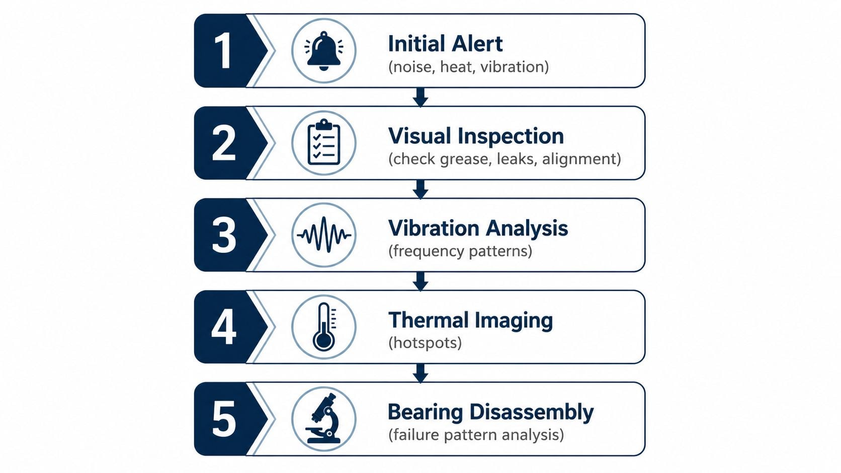
A useful workflow starts with the first alert and ends with evidence, not assumption. The starting signal may be a vibration route alarm, an operator's noise report, or a continuous monitor trip. The team then needs to confirm the symptom, gather the easiest evidence first, and decide whether the failure mechanism points toward lubrication, contamination, electrical stress, or mechanical loading.
A practical sequence on the plant floor
- Initial alert. Confirm the machine, the symptom, and whether the issue is rising or stable. Noise, heat, and vibration often appear together, but the operator's description still helps narrow the failure window.
- Visual inspection. Check grease condition, seals, leakage, mounting hardware, and obvious signs of misalignment or contamination.
- Vibration analysis. Look for defect patterns, changes in the waveform, and trend movement over time.
- Thermal check. Use temperature evidence to support what the vibration data is suggesting, especially when lubrication is suspected.
- Bearing disassembly. Save this step for when the evidence is strong enough to justify opening the machine and documenting the raceway pattern.
A clean failure review benefits from a documented process. The failure analysis workflow guide gives a helpful structure for teams that need to preserve evidence, sequence observations, and avoid jumping too early to a conclusion. That kind of discipline matters on assets that can't be opened twice.
For route-based programs, the best approach is to start with the least invasive measurements and escalate only when the evidence points in one direction. For continuous monitoring, alarms should trigger a short list of checks, not a reflexive shutdown. An internal condition monitoring system overview can help teams decide how to layer route, continuous, and targeted follow-up testing.
The best workflow is boring in the right way. It produces the same answer for the same failure pattern, and that consistency is what lowers repeat failures.
Building a Reliability Program Around Bearing Health
A bearing reliability program works best when it's built into the way the site already manages assets. Route-based vibration, grease control, thermal checks, and current-based diagnostics each solve part of the problem, but they become more effective when they're assigned by criticality. A small auxiliary motor doesn't need the same attention as a feedwater pump or a compressor drive.
Program decisions that actually change outcomes
Lubrication control needs a written procedure, not tribal knowledge. The procedure should define grease type, quantity, interval, and cleanliness controls, because that's where many failures start. VFD-driven motors need a separate review for electrical protection, including shaft grounding and insulated bearing specifications where the application justifies them. A standard bearing change won't fix a current path that still exists.
Criticality ranking matters because it tells the team where continuous monitoring belongs and where route-based inspection is enough. FMEA and RCM thinking help separate the motors that need deep attention from the ones that can be managed with periodic checks and good lubrication practice. That's also where spare strategy fits. If a high-criticality motor is hard to replace, the spare plan should reflect that reality instead of assuming a stocked bearing is enough.
Good programs do three things well: they prevent lubricant-related failures, they detect developing defects early, and they remove the electrical stress that keeps damaging VFD-driven bearings.
Forge Reliability can support that kind of program with predictive maintenance, vibration analysis, oil analysis, thermography, ultrasound, and motor current signature analysis, along with reliability consulting that uses FMEA and RCM to prioritize assets. That matters because bearing health is not just a parts problem. It's an operating model problem, and the program has to match the plant's actual risk.
Calendar schedules alone rarely solve recurring bearing failures. Condition data, failure history, and criticality ranking do.
Real-World Application and Next Steps
A wastewater treatment pump motor shows how quickly a wrong diagnosis can waste a maintenance window. If the bearing runs hot and noisy, the first instinct is often to replace it and return the unit to service. That fix can fail fast if the motor is VFD-fed and the actual problem is electrical bearing damage. It can also miss the mark if the root cause is contaminated grease, because the repair path is different.
The diagnostic decision tree matters more than any single test. Bearing failures dominate motor reliability risk, as noted earlier, but the useful question on the plant floor is which failure mechanism is active on this motor. Lubrication problems, contamination, electrical discharge, and overload all damage bearings, yet they leave different evidence behind. The mistake many sites make is treating every failed bearing as the same problem, then repeating the same repair without checking the clues that separate VFD-induced damage from grease-related wear.
A practical next step is to review the motors that keep repeating the same symptom and classify them by drive type, duty, and criticality. The highest-risk assets deserve a closer look, especially VFD-driven pumps, fans, compressors, and other machines where a bearing failure can stop production. A structured assessment usually shows whether the site needs tighter lubrication control, better electrical mitigation, stronger diagnostics, or a combination of all three. That decision is more useful than a generic replacement plan, because it tells the crew what to change before the next failure reaches the shop floor.
Forge Reliability helps plants build bearing reliability programs around real condition data, not guesswork. A free reliability assessment can identify which motors are most at risk, where repeat failures are coming from, and what diagnostic and maintenance changes will matter most. Visit Forge Reliability to schedule a review and start building a bearing reliability plan that fits the way the facility runs.