
A turnaround inspection finds wall thinning in a pressure vessel or refinery piping circuit. Operations wants the equipment back online, maintenance wants a defensible repair plan, and the reliability engineer has to answer the question that matters most: can the asset run safely until the next planned outage?
That decision rarely fits a simple pass or fail label. A thin area may be acceptable under current pressure and temperature, yet unacceptable if corrosion continues unchecked, if the thinning is concentrated near a nozzle, or if inspection data doesn't describe the flaw accurately. A fitness for service assessment turns that uncertainty into an engineering decision based on damage type, equipment condition, operating loads, and projected deterioration.
The method helps teams distinguish between equipment that can continue operating with controls, equipment that needs a pressure or temperature reduction, and equipment that requires repair or replacement. It also connects the assessment to reinspection timing, condition monitoring, risk-based inspection, and capital planning.
This guide is written for reliability engineers, maintenance managers, and plant operations leaders. It explains how to move from an inspection finding to a practical decision without treating API 579 as a code lookup exercise. By the end, readers should be able to recognize when FFS is appropriate, identify the data an assessment needs, understand when a Level 1 screen must escalate, and translate the result into a safe operating and maintenance plan.
Table of Contents
- Introduction When Thinning Does Not Mean Immediate Shutdown
- What Fitness for Service Means and How It Protects Reliability
- Standards and Acceptance Criteria Behind API 579 ASME FFS-1
- The Fitness for Service Workflow From Data to Decision
- How Key Damage Types Are Assessed in Practice
- Limits Mitigations and Monitoring After the Assessment
- Next Steps to Build FFS Into Your Reliability Program
Introduction When Thinning Does Not Mean Immediate Shutdown
During a turnaround at a chemical plant, an inspector maps the shell of a horizontal pressure vessel with ultrasonic testing. Several readings show wall loss in a corrosion circuit. The thinnest reading attracts immediate attention, but it doesn't answer the operating question by itself. The vessel may still have enough structural capacity, or the local thinning may be more severe than the spot measurement suggests.
Operations asks whether the vessel can return to service. Maintenance asks whether a repair can wait for the next outage. The inspection team asks whether the readings cover the full damaged area and whether the damage is general corrosion, localized metal loss, pitting, or something more serious. These are different questions, and a reliable decision must answer all of them.
A fitness for service assessment exists for this situation. It evaluates an in-service component containing known damage and determines whether the component can continue to operate safely under defined conditions. The evaluation can support continued operation, a rerating, a targeted repair, or replacement. It can also identify the inspection and monitoring actions required before the next decision point.
The important shift is from asking, “Does this vessel meet its original design thickness?” to asking, “Given its current geometry, material, loads, environment, and damage, what operating window remains defensible?” Design codes establish requirements for new equipment. FFS addresses equipment that has accumulated corrosion, cracks, dents, distortion, or temperature-related damage during service.
Plant leaders can use operation and maintenance planning guidance to connect the engineering conclusion with work orders, outage scope, operating controls, and inspection execution. The assessment only creates value when the plant follows through on those actions.
Practical rule: A single low thickness reading is a reason to improve the data set, not automatically a reason to shut down or automatically a reason to continue.
What Fitness for Service Means and How It Protects Reliability
Fitness for service is a structured engineering evaluation of damaged equipment under actual or defined service conditions. The engineer considers the component's flaw, pressure, temperature, mechanical loads, material properties, geometry, and degradation history. The result describes whether the component retains enough integrity for a specified operating period and under specified controls.
A useful analogy is a bridge with a revised weight rating. The bridge was designed for a particular load when new, but an inspection later finds corrosion in a support member. Engineers don't judge the bridge only against its original appearance. They measure the affected member, understand the loads, calculate the remaining capacity, and establish whether traffic must continue normally, be restricted, or stop until repair.
Pressure vessels, piping, tanks, and other pressure-containing equipment can be evaluated in the same way. The original design establishes the baseline. The FFS assessment examines how much that baseline has changed and whether the damaged component can still carry its service loads.
How the decision develops
A sound assessment usually follows a logical sequence:
- Define the component and service. The team confirms geometry, material, pressure, temperature, fluid, cyclic operation, and relevant design information.
- Describe the flaw. Inspection data identifies location, dimensions, orientation, depth, shape, and distribution.
- Classify the damage mechanism. The team determines whether the issue is metal loss, pitting, a crack-like flaw, creep, a dent, or another mechanism.
- Evaluate structural integrity. Calculations compare the measured condition with the applicable acceptance criteria.
- Assess deterioration and operating limits. The present condition is separated from future growth, safe pressure, temperature restrictions, and inspection timing.
- Issue an operating decision. The conclusion may support continued service, rerating, repair, replacement, or additional inspection.
FFS isn't the same as routine inspection. Inspection gathers evidence. FFS interprets that evidence against engineering criteria. It also isn't a substitute for a design code, because a design code governs the creation of new equipment while FFS addresses the condition of equipment already in service.
The outcome should be more precise than “fit” or “unfit.” A defensible report defines the conditions for operation, the remaining-life basis, the reinspection requirement, and the action that will be triggered if the condition changes.
Standards and Acceptance Criteria Behind API 579 ASME FFS-1
Modern FFS practice uses API 579/ASME FFS-1 as a structured framework for evaluating damaged pressure equipment. The standard's first release in 2000 established the key historical anchor for modern FFS programs. A historical overview of API 579 and its development notes that the API CRE FFS Task Group produced the first edition, which quickly became the de facto international FFS standard for pressure-containing equipment in refining and petrochemical service.
The development followed work by ASME's Post Construction Main Committee, formed in the late 1990s to develop standards for equipment already in service. The later joint API and ASME effort helped establish a common framework for major industries such as oil and gas, chemicals, and power generation.
Damage classification controls the assessment path
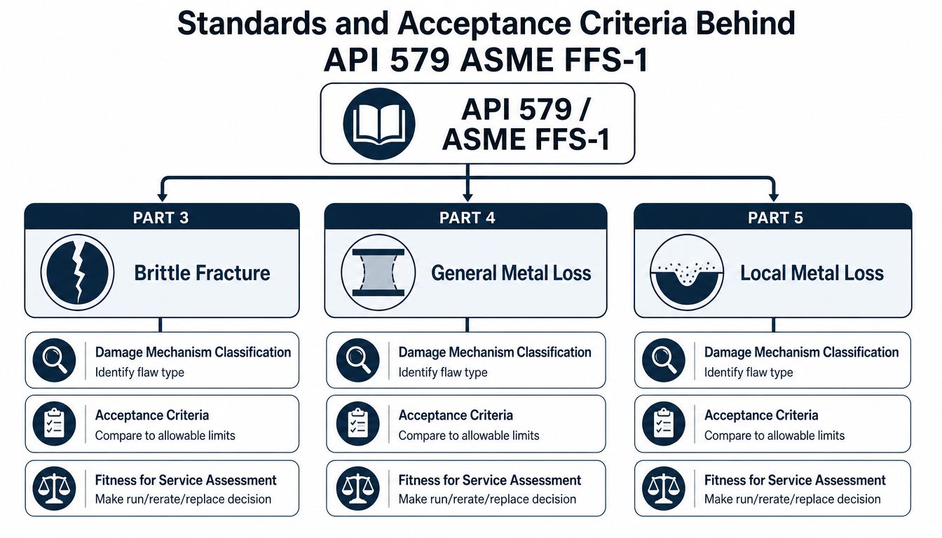
API 579/ASME FFS-1 doesn't apply one formula to every flaw. It maps damage mechanisms to dedicated assessment parts:
| Damage type | API 579 part | Why classification matters |
|---|---|---|
| General metal loss | Part 4 | The assessment focuses on broad wall thinning and remaining thickness distribution. |
| Local metal loss | Part 5 | The geometry and extent of a concentrated thin area influence acceptance. |
| Pitting | Part 6 | Pit depth, spacing, shape, and interaction can control the result. |
| Weld misalignment and out-of-roundness | Part 8 | Geometric discontinuities alter local stress and load distribution. |
| Crack-like flaws | Part 9 | Crack sizing, material toughness, stress, and growth behavior become central. |
| Creep | Part 10 | Time, temperature, stress history, and accumulated damage affect integrity. |
| Dents and gouges | Part 12 | Deformation, metal removal, location, and combined loading shape the risk. |
A refinery elbow with broad thinning doesn't follow the same logic as a steam line with a crack indication. A pitted amine pipe may need a different inspection map from a pressure vessel shell with general corrosion. The first technical decision is therefore damage mechanism classification, not calculation.
A practical introduction to API 579 and ASME fitness for service explains how the parts align specific damage mechanisms with dedicated evaluations. For a reliability team, that means thickness readings, NDE flaw sizing, operating history, and metallurgy data must be assembled before the assessment route is selected.
The standard's value lies in that discipline. It stops teams from treating every defect as generic corrosion and helps them match inspection evidence, failure mode, and acceptance criteria. That alignment is what makes the final run, rerate, repair, or replace decision defensible.
The Fitness for Service Workflow From Data to Decision
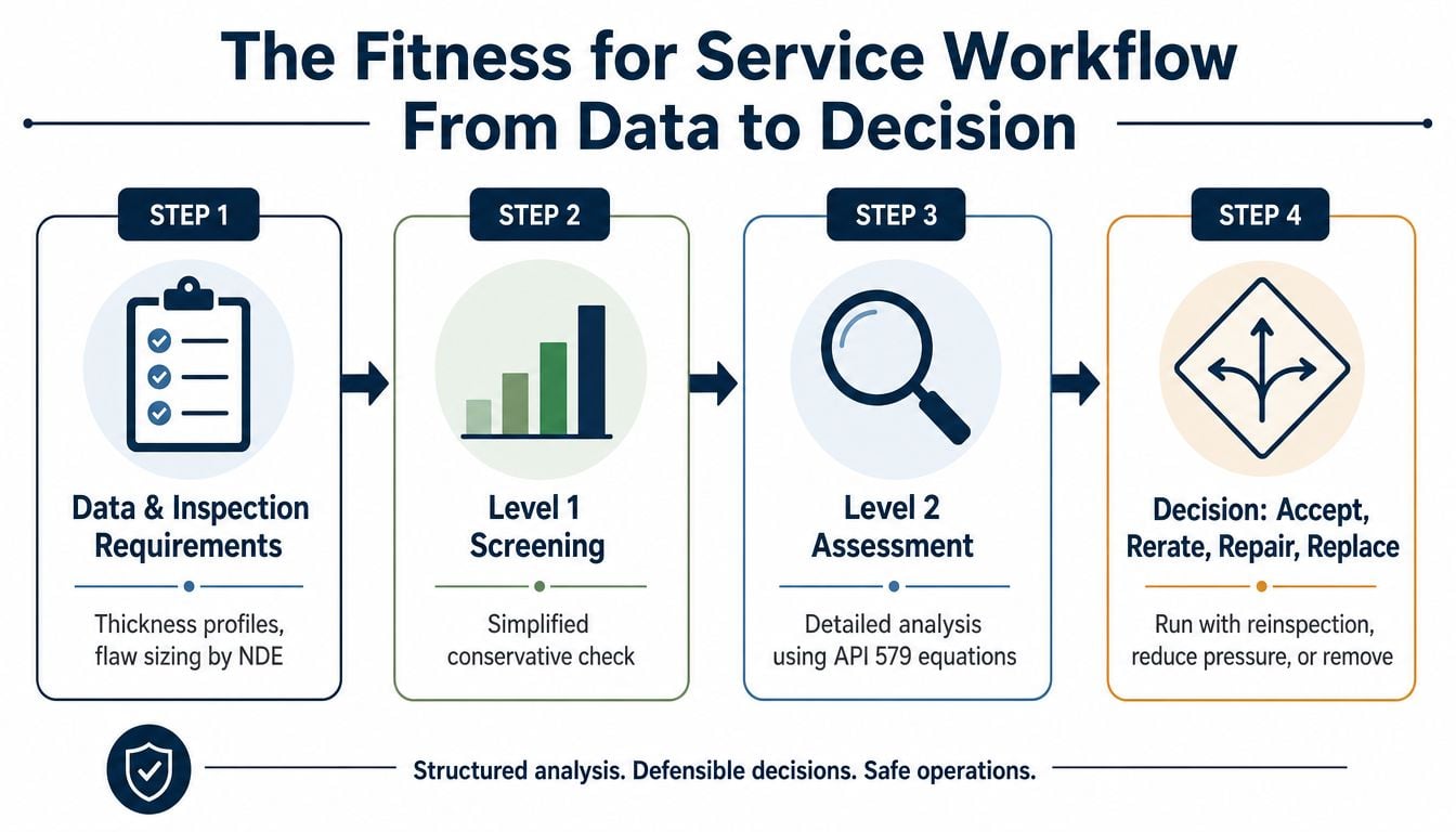
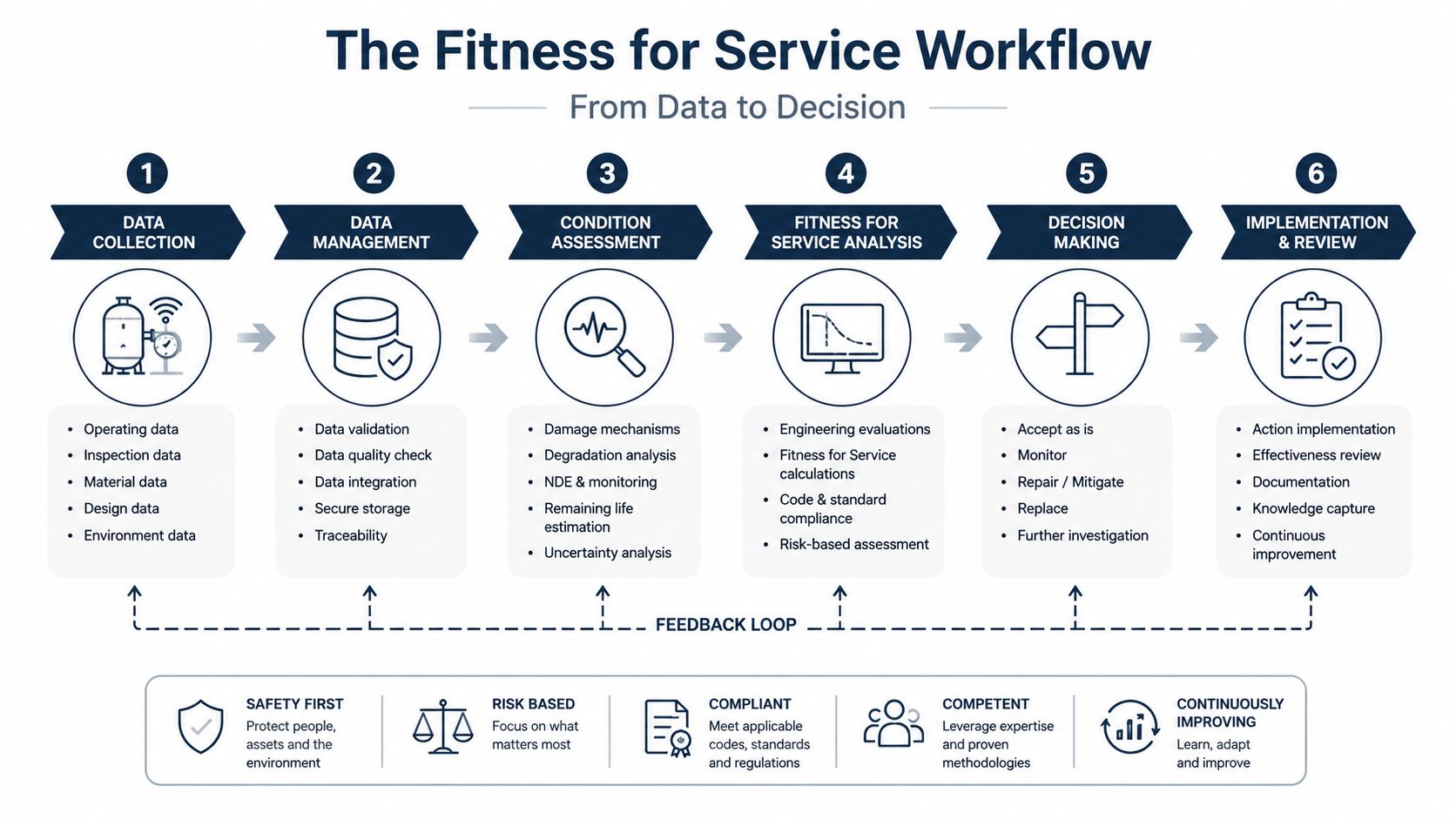
An FFS assessment works best as a decision tree, not as a calculation performed in isolation. The process begins with the asset record and ends with an operating plan that identifies limits, monitoring, and follow-up.
Start with the evidence
The engineering team gathers the information needed to describe both the component and the service:
- Inspection coverage: Thickness grids, thickness profiles, pit mapping, visual findings, and NDE reports establish the flaw's size and distribution.
- Flaw characterization: Crack-like indications require reliable sizing and orientation. Dents and gouges require geometry and location.
- Operating history: Pressure and temperature records, transients, cycling, process chemistry, and upset conditions help define the loads and degradation environment.
- Equipment information: Drawings, dimensions, weld details, material identification, fabrication history, and previous assessments support the calculation basis.
- Degradation history: Earlier inspection results and known corrosion or damage rates help separate current integrity from future condition.
For a refinery piping circuit, a few isolated UT readings may suggest acceptable wall thickness. A thickness profile across an elbow, reducer, dead leg, and downstream valve may show localized thinning caused by erosion or turbulence. The broader map changes the engineering question from “Is the lowest reading acceptable?” to “Does the full damaged geometry satisfy the applicable evaluation?”
Use the least complex defensible level
For general metal loss, API 579 uses a thickness-averaging approach at Level 1, with minimum and average point-thickness readings as initial inputs. If the screening equation isn't met, the process escalates to a thickness-profile-based evaluation, as described in the technical material on general metal-loss assessment.
Level 1 screening is useful when the component, damage, and data fit the simplified method. A failed screen doesn't automatically mean the equipment is unsafe. It means the available simplification cannot support the decision, so the team should improve the data or proceed to a more detailed assessment.
Level 2 uses more detailed calculations and better-defined inputs. Level 3 may be required when geometry, stress interaction, fracture behavior, buckling, or material uncertainty makes simplified methods inadequate. The selected level should reflect the damage complexity and the consequence of an incorrect decision, not just the desire for a quick answer.
Separate today's integrity from tomorrow's condition
A present-integrity check asks whether the component can withstand its current loads now. A remaining-life calculation asks how degradation will progress and when the component may no longer meet the required criteria. Those questions should not be blended.
A documented equipment condition assessment service can help organize the evidence before the engineering decision is finalized. The assessment report should state assumptions, data quality, operating limits, inspection requirements, and escalation triggers.
The final decision may be to continue operating with a defined reinspection date, rerate to a lower pressure or temperature, repair the affected zone, or replace the component. The result should also feed the maintenance plan, risk-based inspection strategy, and operating procedures.
How Key Damage Types Are Assessed in Practice
Different damage mechanisms require different evidence. Treating every finding as wall thinning can hide the actual failure mode, especially when corrosion, stress concentration, temperature, and cyclic loading interact.
| Damage type | API 579 part | Key inputs | What drives acceptance |
|---|---|---|---|
| General metal loss | Part 4 | Minimum thickness, average thickness, thickness profile, geometry, material, pressure, and temperature | Remaining wall distribution and calculated structural capacity |
| Local metal loss | Part 5 | Flaw length, width, depth, profile, location, and nearby stress features | Shape and extent of the thin region, not only the deepest point |
| Pitting | Part 6 | Pit depth, spacing, density, shape, and surrounding thickness | Pit geometry, interaction, and local stress concentration |
| Crack-like flaws | Part 9 | Crack length, depth, orientation, stress, toughness, and growth history | Fracture and plastic-collapse behavior under service loading |
| Creep damage | Part 10 | Temperature history, stress history, deformation, and material condition | Time-dependent deformation, crack development, and remaining life |
| Dents and gouges | Part 12 | Dent geometry, gouge depth, location, restraint, and cyclic loading | Combined deformation, metal removal, and local stress effects |
Metal loss needs a profile, not a single number
General metal loss may occur across a broad shell or pipe surface. Local metal loss may be concentrated near a nozzle, elbow, weld, support, or erosion zone. A single spot UT reading can look acceptable while the surrounding profile reveals a larger damaged region.
The overview of ultrasonic testing equipment is relevant because measurement quality and coverage determine whether the assessment describes the actual geometry. For a chemical reactor vessel, a mapped profile around an inlet nozzle can distinguish broad corrosion from a sharp erosion groove. That distinction affects both the applicable assessment and the repair boundary.
Cracks require fracture-focused evidence
A crack-like flaw in amine piping or a pressure-vessel weld isn't evaluated like corrosion. The team needs dependable crack sizing, orientation, stress information, material toughness, and a credible basis for understanding whether the crack can grow under service conditions. Weld location, thermal cycling, residual stress, and process chemistry may all influence the decision.
A crack indication that appears small on a surface examination may still be significant if it is aligned with a high-stress region. Conversely, a flaw may be manageable if the assessment demonstrates acceptable behavior under defined operating and inspection controls.
Temperature damage depends on history
Creep affects equipment exposed to high temperature over time, such as a steam drum, high-temperature header, or process transfer line. The assessment must account for the service history rather than relying only on the current temperature reading. Changes in operating regime, local overheating, metallurgical condition, and deformation can alter the remaining-life picture.
Pitting and erosion also depend on location. A pit in low-stress tankage may demand a different response from a pit at a pressure boundary transition. A dent in a low-consequence area isn't automatically equivalent to a dent near a weld or cyclically loaded connection. Geometry, location, and loading determine severity.
Limits Mitigations and Monitoring After the Assessment
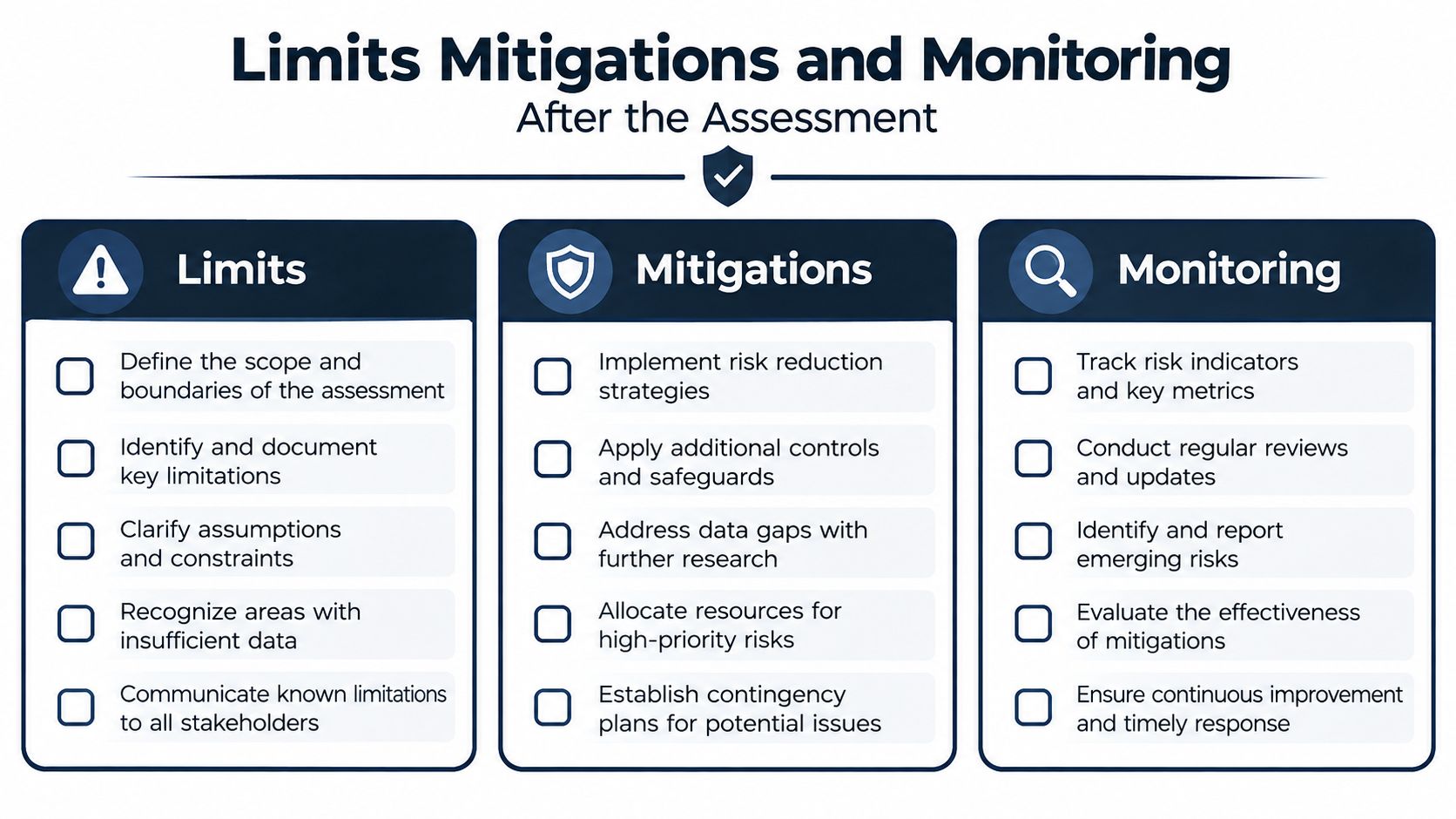
An FFS report is useful only when plant personnel can convert its conclusion into controlled operating actions. The result should state what the equipment may do, what it must not do, and what evidence will trigger a new review.
Translate the result into an operating boundary
Continued service may be appropriate when the assessment supports the current pressure and temperature, the inspection data is adequate, and the degradation rate can be managed. That decision still needs a defined reinspection date, required NDE method, and clear limits on process changes.
Rerating can be appropriate when a lower pressure or temperature reduces the controlling stress sufficiently. The plant must then control the new limit through procedures, alarms, operator rounds, and management of change. A rerating decision isn't effective if the original operating envelope remains in the control system.
Repair or replacement becomes the responsible path when the damage exceeds the applicable criteria, uncertainty prevents a defensible conclusion, or the mechanism can progress faster than the monitoring plan can detect. A pulp mill digester with shell thinning may remain operational under restricted conditions only if the inspection coverage, corrosion control, and planned repair are all documented. An oil and gas separator with local metal loss near a nozzle may need a targeted repair rather than a broad replacement, depending on the calculated condition and consequence of leakage.
Treat uncertainty as an engineering input
Uncertainty in NDE sizing, sparse thickness coverage, unknown material properties, interacting damage, or uncertain creep crack growth can change the decision. The appropriate response may be additional inspection, a more advanced assessment, a conservative operating restriction, or immediate repair.
Escalation trigger: If the plant can't explain how the flaw will be detected before it reaches the assessment limit, the monitoring plan isn't complete.
Monitoring should match the failure mode. Thickness mapping supports corrosion and erosion management. Ultrasound can support targeted inspection of wall loss or selected discontinuities. Thermography can identify abnormal thermal patterns around process equipment, while vibration monitoring is more relevant to rotating equipment that may impose cyclic loads on connected piping. These techniques should support, not replace, the FFS evaluation.
The result should also connect with FMEA, criticality ranking, and risk-based inspection. A critical separator with uncertain flaw growth deserves a different follow-up strategy from a low-consequence utility line. Teams can use condition monitoring systems to build the required measurements into route-based or continuous monitoring plans, provided the monitoring method can detect the relevant change.
Next Steps to Build FFS Into Your Reliability Program
Reliability teams get the strongest results when FFS is part of the asset strategy before an inspection finding becomes an outage crisis. Critical pressure vessels, piping circuits, tanks, steam systems, and high-temperature components should have accessible records for geometry, materials, operating history, inspection results, and prior engineering decisions.
A practical program starts with asset prioritization:
- Rank consequence first: Identify equipment where loss of containment, production interruption, or personnel exposure would create the most serious outcome.
- Capture condition data consistently: Store thickness locations, flaw dimensions, NDE methods, process conditions, and inspection dates in a controlled record.
- Preserve decision history: Keep the assumptions, operating limits, repair status, and reinspection requirements with the asset record.
- Connect engineering to planning: Use the result to shape outage scope, spare parts, repair materials, capital requests, and replacement timing.
- Review after process changes: A change in pressure, temperature, chemistry, cycling, or equipment duty can invalidate the original assessment basis.
FFS shouldn't become a one-time calculation filed away after a turnaround. It should remain connected to inspection execution, corrosion control, operating discipline, condition monitoring, and lifecycle planning. A properly governed CMMS asset management program helps keep the technical decision visible to planners, supervisors, operators, and future engineers.
The central question is simple: does the plant have enough trustworthy data to make the next integrity decision before the equipment reaches its limit? If the answer is uncertain, the next action should be a data-quality review and a prioritized assessment of the most critical assets.
Forge Reliability offers a free reliability assessment to review critical equipment, inspection data, condition monitoring coverage, and remaining-life decision needs. Visit Forge Reliability to identify practical actions for safer operation, better outage planning, and stronger asset reliability.