At 3 AM, the call usually sounds the same. A main transformer tripped, production is down, operators are waiting, and no one can answer the question that matters most. Was this a sudden event, or was the warning there for weeks and no one connected the dots?
That's the operational reality behind transformer reliability. A failed transformer doesn't just damage electrical equipment. It can shut down an entire line, stall utilities to critical process areas, create safety exposure for electricians and operators, and force plant leaders into expensive, rushed decisions under pressure. In a steel mill, chemical plant, or automotive facility, the transformer often sits in the background until it becomes the single point of failure everyone is talking about.
The practical answer isn't more calendar-based work by itself. The answer is condition monitoring of transformer assets that ties internal fault indicators to actual operating conditions. That shift is what separates routine inspection from true predictive maintenance.
Table of Contents
- Why Transformer Health Demands More Than a Calendar
- The Core Diagnostic Toolkit for Transformer Monitoring
- Interpreting Data to Pinpoint Specific Failure Modes
- Choosing Your Strategy Offline Sampling vs Online Sensors
- From Data to Action Integrating Alarms with Your CMMS
- Build Your Proactive Transformer Reliability Program
Why Transformer Health Demands More Than a Calendar
A plant can follow every scheduled PM on paper and still miss the fault that matters. That happens when the maintenance strategy is built around dates instead of equipment condition. Transformers don't fail because the calendar turned. They fail because heat, moisture, insulation stress, mechanical movement, and internal electrical faults crossed a line that no one detected in time.
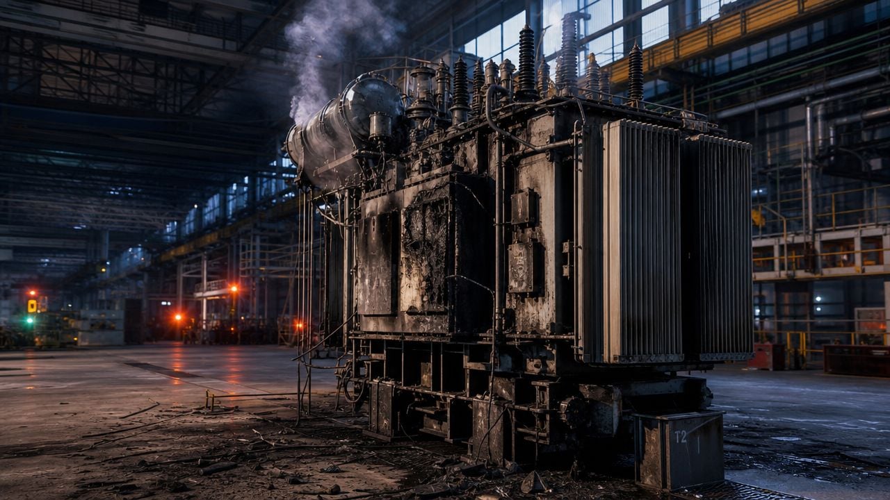
A food processing plant offers a familiar example. The facility has a substation transformer feeding refrigeration, packaging, and compressed air support loads. The transformer passes routine inspection rounds, but one weekend it trips under load. The root problem wasn't the age of the asset alone. It was that no one had linked internal degradation to rising operating stress during production peaks.
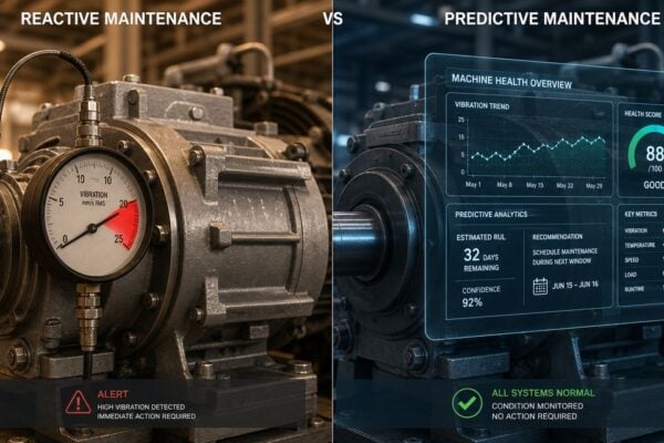
That's why condition monitoring of transformer assets has to be treated as a business decision, not a lab exercise. It protects uptime, avoids forced outage work, and gives maintenance leaders time to plan instead of react. Teams deciding between time-based and condition-based strategies can see the broader maintenance trade-off in this discussion of predictive vs preventive maintenance.
Practical rule: A transformer that looks stable during monthly review can still be deteriorating quickly between samples.
Calendar work still has a place. Plants need inspections, cleaning, connection checks, oil sampling routes, and documented test intervals. But by itself, a calendar won't tell a maintenance manager whether a unit is aging normally or moving toward a fault that threatens the next production run.
The difference matters most on critical assets. A spare motor might be swapped in a few hours. A failed transformer can leave operations waiting on diagnosis, switching plans, rental power discussions, and emergency repair logistics that no plant wants to manage in the middle of the night.
The Core Diagnostic Toolkit for Transformer Monitoring
A useful transformer monitoring program answers four different questions. Is an internal fault developing. Is the insulation system losing margin. Has a fault or through-event shifted the windings. Are operating conditions accelerating damage between inspection points. Plants that separate those questions get better decisions than plants that rely on a single monthly sample.
DGA as the internal fault screen
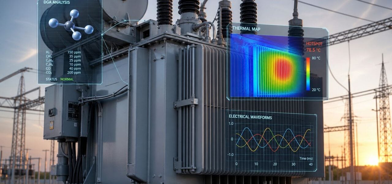
Dissolved Gas Analysis (DGA) remains the primary screen for internal problems in oil-filled transformers. It measures gases generated inside the tank and uses the pattern of those gases to identify the type of stress developing, such as overheating, partial discharge, or arcing.
In practice, DGA earns its value when the team treats it as trend data tied to operation, not just a lab report filed away after sampling. A gas rise after a period of heavy loading, cooling fan problems, or repeated process swings means more than the same gas rise on a lightly loaded stable unit. That correlation is what moves a plant from reactive troubleshooting to predictive management.
DGA also helps narrow the work scope. If the pattern points to thermal distress, maintenance should check load history, cooling performance, connections, and tap changer condition. If it points to discharge activity, the priority shifts toward insulation stress, internal clearances, and defect progression.
Oil quality and insulation condition
DGA gets attention because it can flag active faults. Oil quality testing shows whether the insulation system still has the strength to handle normal duty and upset conditions.
The oil has two jobs. It insulates. It removes heat. When moisture, oxidation products, or contamination build up, dielectric strength drops and heat transfer suffers. A transformer can pass a visual inspection and still be operating with less margin than the plant believes it has.
Useful oil-focused checks often include:
- Moisture condition: Water in oil and paper reduces dielectric strength and accelerates insulation aging.
- Dielectric integrity: These tests show whether the oil can still withstand electrical stress.
- Acid formation: Rising acidity indicates oxidation and long-term deterioration of the oil-paper system.
- Trend direction: Repeated results over time carry more decision value than one acceptable sample.
A single clean sample can create false confidence if load profile, ambient conditions, or cooling duty changed since the previous test.
This is one of the most missed links in transformer care. Plants often review oil results in one meeting and operating history in another. The failure risk sits in the overlap.
Electrical and mechanical checks
Electrical tests answer a different set of questions than oil tests. They confirm insulation condition, ratio accuracy, and dielectric losses, and they help verify whether the unit changed after commissioning, outage work, or a fault event.
Typical checks include the following:
| Test type | What it helps reveal | Typical use case |
|---|---|---|
| Insulation resistance | General insulation condition | After outages, repairs, or moisture concern |
| Power factor testing | Dielectric losses and insulation deterioration | Aging fleet assessment |
| Turns ratio testing | Winding ratio issues and tap changer concerns | Commissioning or post-event verification |
Mechanical condition also matters. Through-fault forces can move windings even when the transformer stays in service afterward. That kind of damage may not show up clearly in routine oil work right away, which is why electrical and mechanical verification still belongs in the toolkit.
Frequency Response Analysis (FRA) is commonly used to detect winding movement or deformation by comparing the transformer's measured electrical response with a known baseline or a comparable phase. Plants usually get the most value from FRA after transport, after major faults, or when other tests suggest something changed mechanically.
For plants building a broader program, condition monitoring services for electrical assets typically combine oil analysis, thermography, ultrasound, vibration where applicable, and electrical testing. That combination gives maintenance and operations a better basis for deciding whether to keep running, reduce load, plan an outage, or escalate immediately.
Interpreting Data to Pinpoint Specific Failure Modes
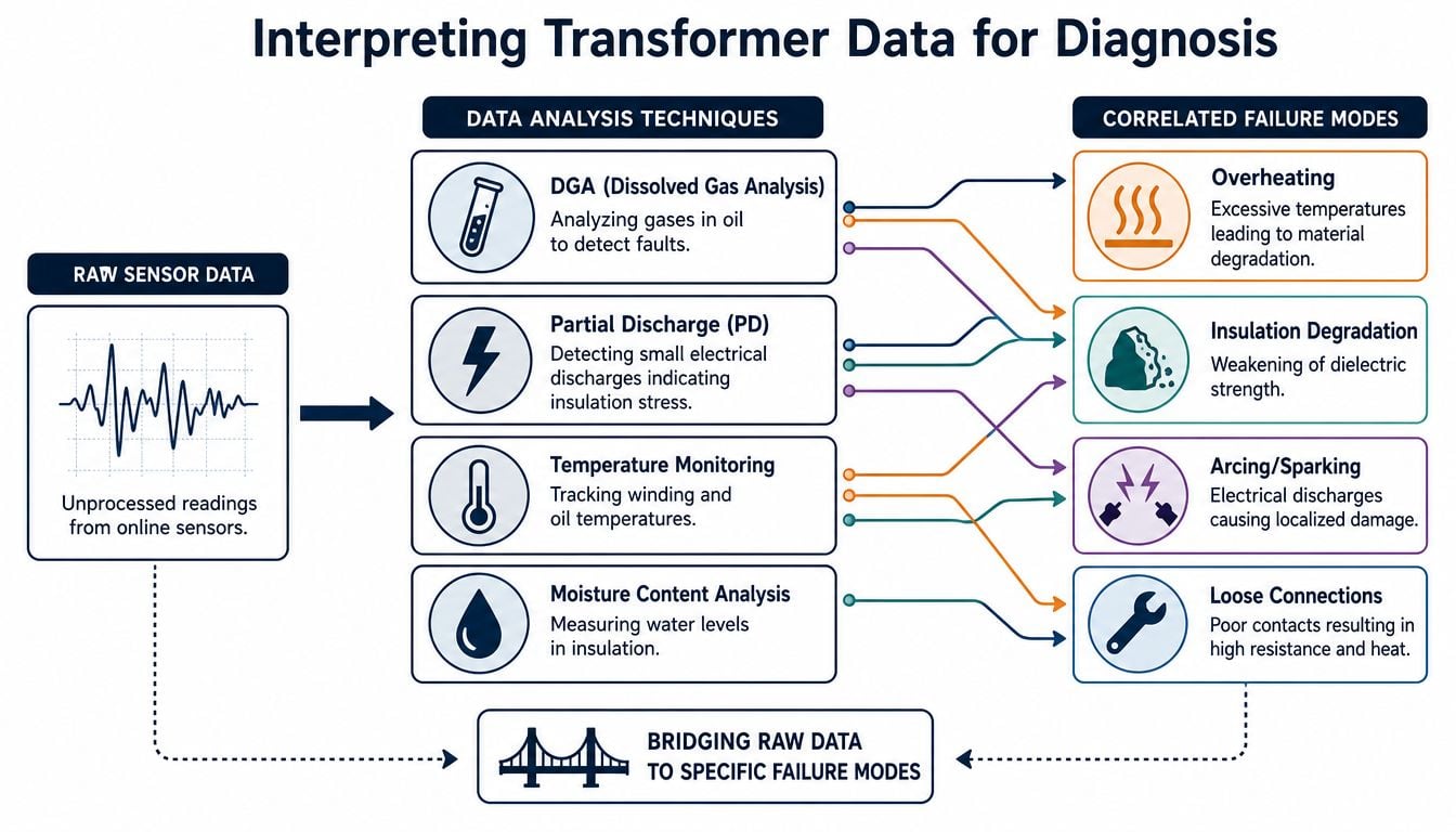
A transformer can look stable right up to the week it forces an outage. The usual pattern is familiar. A gas result trends up, operators mention higher load or repeated starts, someone sees a temperature shift, and each signal gets reviewed on its own. Plants miss failures when those pieces never get tied together.
Interpretation works when the team reads condition data against operating stress. A gas value by itself is only part of the story. A temperature point without load history is only part of the story. A partial discharge alarm without severity, trend, and process context is only part of the story.
Turning gas data into a fault diagnosis
DGA becomes useful when engineers examine both individual gases and their relationships. Methods such as the Duval Triangle and gas ratios help sort likely fault types, but the stronger diagnosis comes from comparing those results with loading, cooling performance, and recent operating events.
The practical question is simple. Is the transformer aging normally, or is it developing a fault that will get expensive fast?
According to this transformer condition monitoring reference, acetylene (C₂H₂) above 10 ppm points to high-energy arcing, hydrogen (H₂) above 500 ppm suggests severe dielectric breakdown or moisture-related distress, and a C₂H₄/C₂H₆ ratio greater than 1 generally indicates a high-temperature thermal fault associated with rapid insulation damage.
Those indicators support action when they are read in context:
- Acetylene rising above threshold: Investigate arcing or another high-energy internal event. If the unit also saw recent switching events, process upsets, or through-fault exposure, treat the condition as active until testing proves otherwise.
- Hydrogen in the severe range: Check dielectric condition, moisture, and any change in operating duty. A heavily loaded transformer with marginal cooling can move from abnormal to urgent quickly.
- Ethylene-to-ethane ratio above 1: Treat it as a serious thermal warning, especially if top-oil temperature, fan status, or load profile changed around the same time.
This correlation is where many programs either become predictive or stay reactive. A quarterly oil sample may show a manageable increase in gas generation. The same result paired with repeated overloads, cooling control problems, and rising thermal trends points to a fault that is being driven by operation, not just age.
Plants that need better interpretation often benefit from oil analysis support tied to asset criticality and operating history rather than stand-alone lab reporting. The value is not the report by itself. The value is deciding whether to keep running, reduce load, schedule an outage, or inspect immediately.
Reading partial discharge for actionability
Partial discharge (PD) is localized electrical discharge that does not fully bridge insulation between conductors. It usually indicates insulation stress, contamination, voids, or a developing internal defect. Detection matters, but response quality matters more.
A PD alarm should never be reviewed in isolation. If PD activity increases while the transformer is carrying higher cyclic loads, running hotter than normal, or showing gas changes associated with insulation distress, the probability of a meaningful defect goes up. If PD appears without supporting evidence, the next step is confirmation and closer monitoring, not guesswork.
A practical interpretation framework looks like this:
| PD condition | What it means in practice | Typical response |
|---|---|---|
| First warning | Early insulation stress may be present | Increase monitoring and inspect related evidence |
| First fault signal | Fault development is more credible | Plan targeted outage and confirm with supporting diagnostics |
| Critical condition | Failure risk is unacceptable | Move to immediate intervention planning |
If PD rises while operators also report unusual sound, odor, or heat near the transformer, treat it as an integrated fault investigation.
In an automotive plant, a transformer feeding robotic welding and paint support systems may stay online while PD grows in the background. Continued operation does not confirm health. The sound decision is to review PD severity alongside oil condition, thermal behavior, and load profile, then set outage timing based on failure risk and production consequence.
That is the difference between collecting readings and diagnosing failure modes. One approach produces reports. The other protects uptime and capital.
Choosing Your Strategy Offline Sampling vs Online Sensors
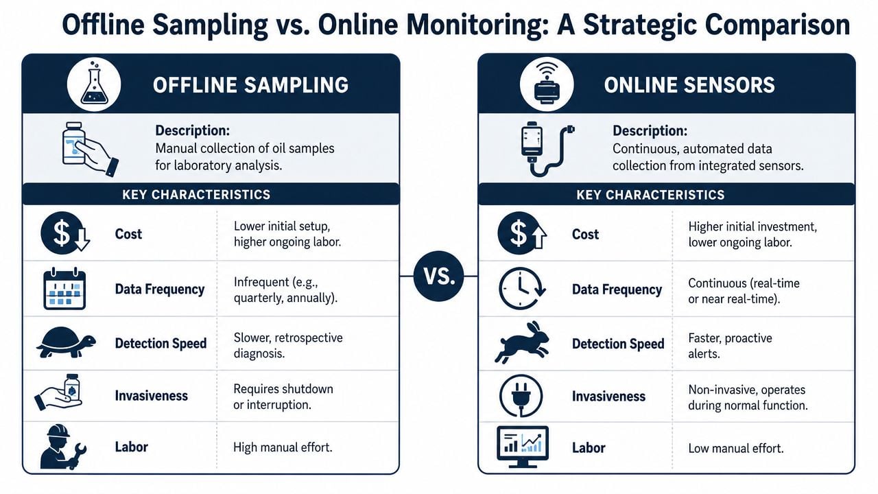
The collection method shapes the quality of every decision that follows. Plants often debate whether traditional oil sampling is enough or whether critical transformers need continuous monitoring. The honest answer is that both methods have a role, but they don't solve the same problem.
What offline sampling still does well
Offline sampling remains useful because it's familiar, relatively simple to deploy, and effective for broad fleet screening. For lower-criticality units, it may be the right economic choice. A plant with several non-bottleneck distribution transformers doesn't need to put continuous sensors on every tank.
There's also diagnostic depth in a properly handled oil sample. A lab can support fault interpretation, moisture assessment, and broader oil condition review in a way that still fits many maintenance budgets and staffing models.
Offline sampling tends to work well when these conditions are true:
- Asset criticality is moderate: An unplanned trip won't stop the entire site.
- Load profile is stable: The transformer doesn't see sharp operational swings.
- Failure progression is expected to be slow: The team has time to react between samples.
- Field access is manageable: Sampling can be done safely and consistently.
Where online monitoring changes the decision
The limitation of offline methods is timing. A periodic sample gives a snapshot, but many transformer problems don't develop on a convenient schedule. The most important missed issue in many aging fleets is the gap between intermittent internal data and real-time operating data.
According to the overview of transformer condition monitoring, the gap between intermittent sampling and real-time thermal correlation is a critical challenge. Without IIoT sensors tracking hotspots simultaneously with gas evolution, maintenance teams can't distinguish between background aging and accelerated fault progression, which causes missed opportunities for prioritized maintenance before escalation.
That point changes the whole strategy discussion. The key value of online monitoring isn't just faster data. It's correlated data.
A chemical processing plant offers a strong example. A transformer may show a modest gas change that doesn't look urgent by itself. If that same period also shows recurring hotspot behavior during specific load ramps, the diagnosis changes. The team is no longer looking at generic aging. It is looking at a fault that reacts to operating conditions and may be advancing faster than periodic sampling suggests.
A useful comparison is below:
| Decision factor | Offline sampling | Online sensors |
|---|---|---|
| Best fit | Lower-risk assets | Critical transformers |
| Strength | Broad screening and periodic diagnostics | Real-time visibility and trend correlation |
| Weakness | Misses changes between samples | Higher setup effort |
| Operational value | Supports planned review | Supports fast maintenance prioritization |
Thermal correlation is especially important because temperature drives insulation stress, accelerates degradation, and can expose load-dependent defects. Plants using thermographic inspection alongside online transformer monitoring are usually trying to answer one practical question. Is the thermal behavior consistent with the internal fault signature, or is the asset entering a different risk category?
Continuous data without operating context becomes noise. Operating context without internal fault data becomes guesswork.
For a critical substation transformer feeding a bottleneck process, online sensing is often justified not because the technology is newer, but because the failure consequence is too high for blind intervals between samples.
From Data to Action Integrating Alarms with Your CMMS
At 2:10 a.m., a transformer alarm comes in during a production run. The operator sees a gas trend warning on one screen, rising load on another, and no work request in the maintenance system. By day shift, the question is no longer whether the transformer changed condition. The question is whether the plant lost half a shift because the information never turned into action.
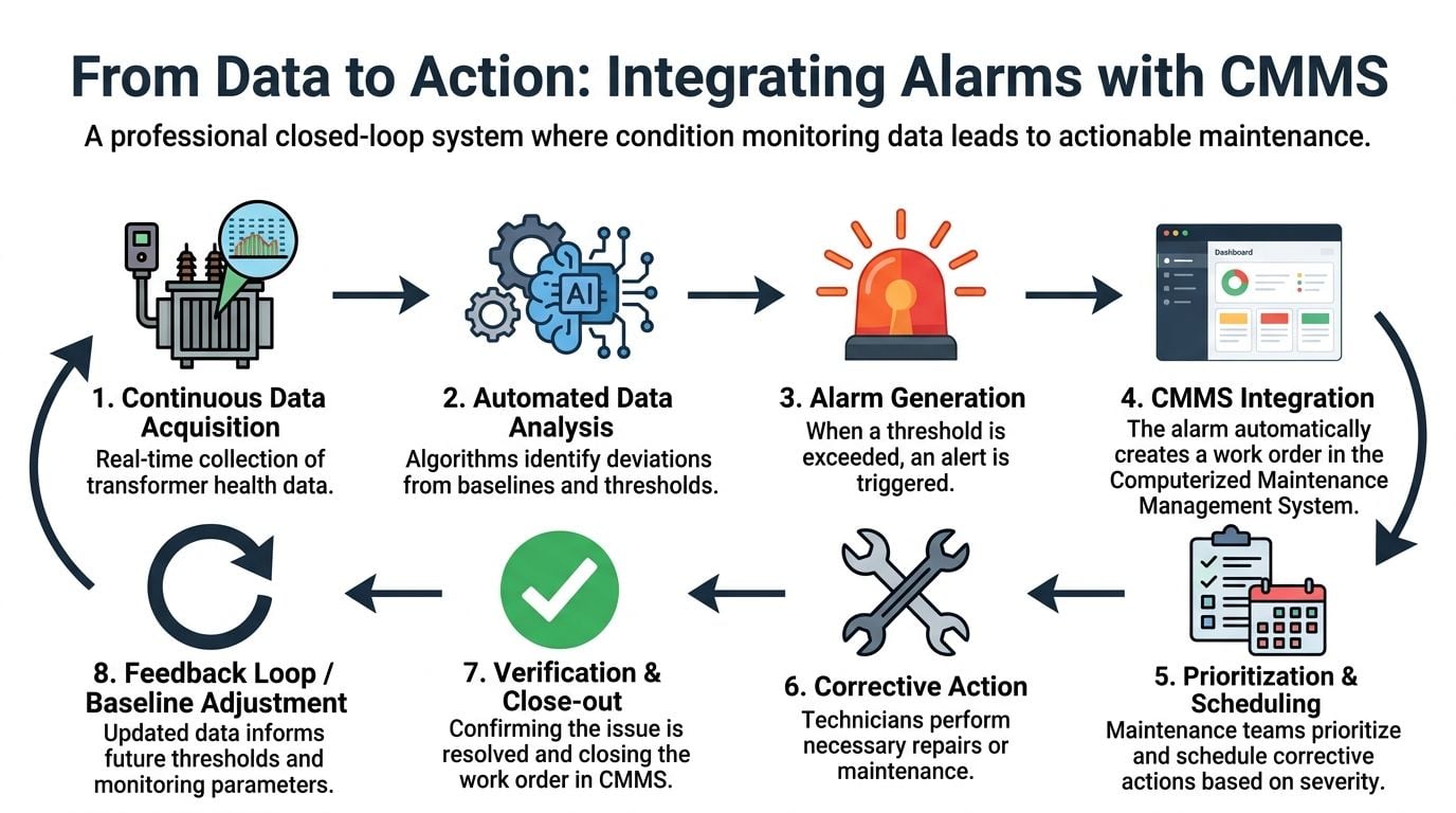
That gap is where plants lose money. Monitoring only pays back when abnormal condition, operating context, and maintenance execution are tied together fast enough to change the outcome. For transformers, that means correlating intermittent diagnostic inputs such as DGA with live signals such as load and temperature, then pushing a clear maintenance response into the CMMS.
Set alarms on trend, not just limits
Static limits still matter. They catch obvious bad conditions. They do a poor job of catching deterioration early, especially when the transformer is still operating inside nominal ranges.
A better alarm structure watches direction, rate of change, and correlation. If hydrogen is climbing, top oil temperature is rising faster than expected for the present load, and the same unit has shown moisture instability, that combination deserves a different response than a single isolated high reading. Plants that miss this point usually end up with one of two bad outcomes. They either flood the team with nuisance alarms or stay quiet until the condition is severe enough to force an outage.
Useful alarm logic usually includes four parts:
- Asset-specific baseline: Compare each transformer against its own normal behavior, not a generic site-wide number.
- Rate-of-change detection: Flag deterioration that is accelerating, even when absolute limits have not been crossed.
- Cross-signal validation: Raise priority when fault indicators move with operating variables such as load, winding temperature, or cooling changes.
- Action-based severity: Tie each alarm state to a defined response, such as review within 24 hours, field inspection this shift, or immediate operating restrictions.
Partial discharge is a good example. Early activity may justify review and closer watching. Repeated or escalating activity, especially when it lines up with thermal stress or switching events, should trigger a different work path with tighter response time and a clearer escalation route.
Build a closed maintenance loop
Once alarm logic is credible, the next failure point is workflow. If the monitoring system identifies a probable fault, but a planner has to copy readings into email and create a manual work order later, the plant is still relying on memory and individual follow-through.
The CMMS should receive a structured event with enough context to support a decision the same shift. That usually includes the affected asset, severity, recent trend, related operating conditions, and the recommended first action. The goal is not more data. The goal is faster triage.
A practical workflow for transformer alarms usually includes:
- Automatic work request creation: The monitoring system sends a defined event into the CMMS.
- Diagnostic context attached: Trend plots, alarm history, and related operating notes travel with the work.
- Priority by consequence: A main process transformer and a low-consequence auxiliary unit should not enter the same queue the same way.
- Prebuilt task steps: Inspection, oil sampling, infrared check, relay review, and verification tasks are already mapped for the fault type.
- Close-out feedback: Technician findings update asset history so future alarms can be tuned against real failure evidence.
One example. An online monitor shows worsening moisture behavior after repeated high-load periods on a transformer feeding a paint line. The CMMS work request includes the trend, the recent load pattern, and the thermal response. The electrician arrives with a likely fault path in mind instead of starting with a blank page.
That shortens diagnosis time. It also reduces the chance of wasting a planned outage on the wrong inspection scope.
Plants that want this process to work consistently often need more than alarm setup. They need priority rules, asset criticality, job templates, and escalation paths configured inside the maintenance system. That is why transformer monitoring programs are often paired with CMMS implementation support for reliability workflows so condition data drives planned work instead of sitting on a dashboard.
The common mistake is overbuilding the alarm list. A smaller set of meaningful alarms tied to fault progression, operating stress, and business consequence will outperform a long list of generic notifications every time. When the right alarm reaches the right person with enough context to act, transformer monitoring stops being a reporting exercise and starts preventing production loss.
Build Your Proactive Transformer Reliability Program
A furnace trips at 2 a.m., production is down, and the first question from operations is simple: did the transformer give us any warning? In many plants, the honest answer is yes, but the warning sat in a monthly oil report, separate from the load spikes and temperature stress that explained why the fault was developing.
A proactive program starts with criticality. Classify transformers by business consequence first. Loss of the unit might stop a line, damage upstream equipment, affect safety functions, or force expensive load transfers. That decision sets the monitoring level far better than a blanket rule to put the same sensors and tests on every asset.
The program itself is straightforward, but the discipline matters. Define which transformers are production-critical. Match each class to the right monitoring method. Set clear rules for how engineers and technicians interpret changing results. Then make sure those findings trigger planned maintenance before the asset forces an outage.
The missed step is usually correlation.
DGA, moisture, and oil quality data can identify developing internal problems. By themselves, though, they only show part of the picture. True value comes from tying those intermittent indicators to operating history such as load swings, peak thermal periods, cooling performance, and alarm events. That is how a plant moves from "something may be wrong" to "this fault is progressing under these conditions, and we should act during the next planned window."
A metals plant illustrates the trade-off well. The main furnace transformer often justifies continuous monitoring because a failure carries high production and repair cost, and because loading is severe enough to accelerate insulation aging or moisture migration. An auxiliary transformer with lower consequence may be better served by route-based oil sampling and periodic electrical testing. Both approaches can be right. The wrong approach is treating both assets as if they deserve the same money, the same attention, and the same response time.
Good programs also account for who will use the information. An online monitor without load context creates noise. A lab report without a decision rule creates delay. A maintenance team with neither operating history nor fault interpretation usually defaults to either overreacting with unnecessary work or underreacting until the damage is obvious.
Condition monitoring of transformer assets becomes predictive only when internal condition data and real operating stress are reviewed together. Plants that do this well spend less on emergency response, avoid unnecessary intrusive work, and make outages shorter because inspection scope is based on a likely failure path instead of guesswork.
Forge Reliability helps plants build transformer monitoring programs that connect oil analysis, thermal data, alarm logic, and maintenance execution into a practical reliability workflow. If a facility needs help deciding which transformers deserve online monitoring, how to interpret developing fault signatures, or how to turn alerts into planned work, request a free reliability assessment from Forge Reliability.