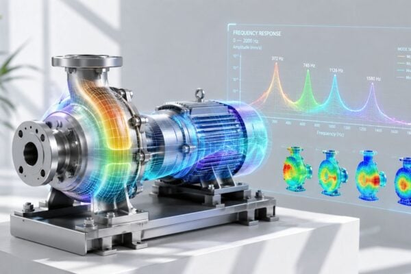
A pump motor has just failed, and the catalogue says the bearings should have run for years. The replacement bearing is the same size, the calculated load is unchanged, and the maintenance team is already preparing to repeat the installation. That response misses the central problem with bearing life calculation: the formula can be correct while the assumptions are wrong.
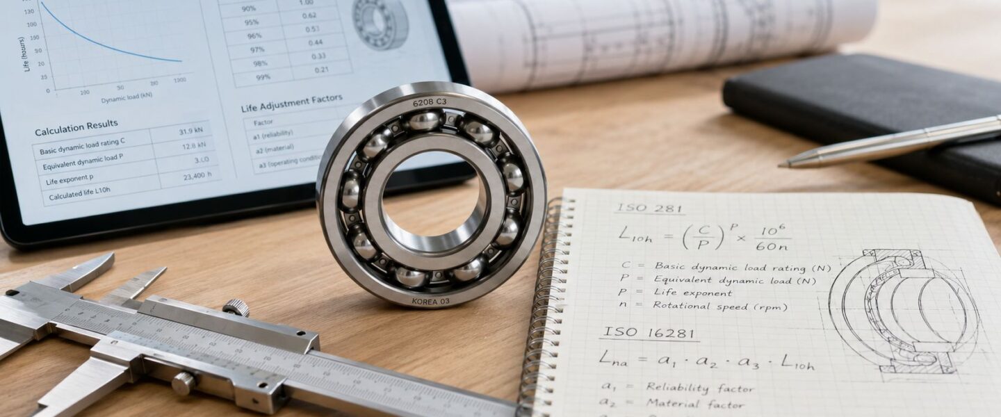
A useful calculation starts with ISO 281, then tests whether lubrication, contamination, alignment, clearance, internal load distribution, standby vibration, and transport conditions support the result. ISO 281 supplies a baseline. ISO 16281 helps explain whether that baseline resembles the plant floor.
Table of Contents
- Why Bearings Still Fail Before Their Calculated Life
- Gathering the Inputs for ISO 281
- Calculating Equivalent Dynamic Load
- Computing Basic Rating Life L10
- Moving From L10 to Adjusted Life With ISO 16281
- Matching the Right Life Model to the Application
- Turning Bearing Life Numbers Into Maintenance Strategy
Why Bearings Still Fail Before Their Calculated Life
A 22 kW centrifugal pump motor in a wastewater plant failed after 14 months. Its 6205-2RS bearings carried a catalogue L10 rating life of 40,000 hours, yet the calculation didn't predict the failure.
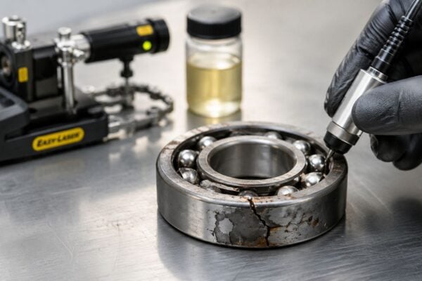
The post-failure inspection found three interacting mechanisms. Water had entered past a failed seal, grease had been washed from the contact zones, and microscopic brinelling had developed while the motor sat on standby near running equipment. The raceways showed damage that could not be explained by running hours alone.
The calculation had used a clean, correctly lubricated, properly aligned bearing under a representative load. The machine had experienced wastewater moisture, degraded grease, shaft vibration during idle periods, and an installation condition that allowed those weaknesses to persist. The number wasn't useless. It was incomplete.
What L10 actually means
L10 is a statistical rating life, not a warranty. It represents the life at which 90% of a group of identical bearings are expected to survive under the stated load and speed. The remaining 10% may fail earlier, even when the calculation has been performed correctly, as explained in technical guidance on basic rating life and bearing load capacity.
That statistical definition matters during a failure review. A bearing that fails before L10 hasn't automatically disproved the calculation. However, repeated early failures usually indicate that the operating conditions, load model, installation, or preservation process doesn't match the assumptions.
Practical rule: Treat L10 as a selection benchmark. Treat recurring early failures as evidence that the system around the bearing needs investigation.
Where the baseline breaks
The basic ISO 281 approach doesn't fully capture several field drivers. Lubrication, contamination, misalignment, operating clearance, fatigue load limit, tilting, and internal load distribution can materially change the reference life. ISO 16281:2025 specifically expands modified reference life calculations to account for these conditions beyond the basic ISO 281 approach in its standard description.
For the wastewater pump, the maintenance decision isn't just "install a bearing with a higher C rating." The team needs to inspect seal design, shaft condition, grease compatibility, standby vibration, fits, alignment, and the motor's storage routine. That is the difference between solving a bearing-size problem and solving a system problem.
The same distinction applies to motors, gearboxes, conveyors, and pump trains. Catalog life starts the discussion. Failure evidence determines where the discussion goes next.
Gathering the Inputs for ISO 281
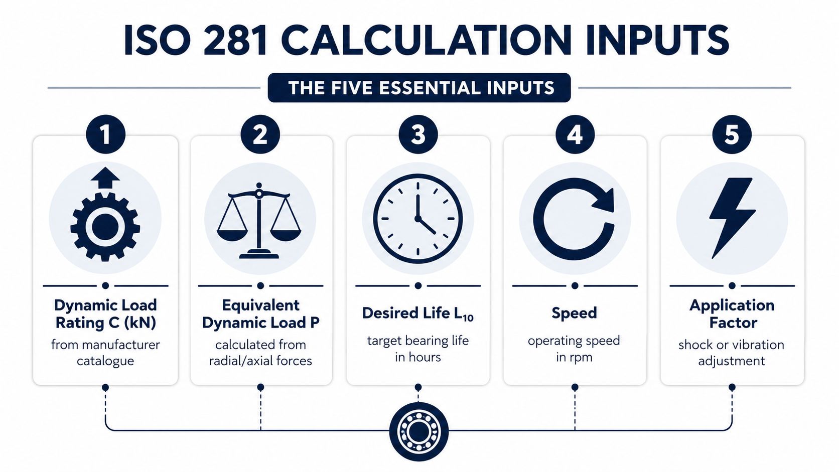
A sound ISO 281 calculation depends on five inputs assembled in a disciplined order. The arithmetic is easy to repeat. The input review is where most of the engineering judgment sits.
The five-input sequence
Dynamic load rating C. The manufacturer's catalogue gives C in kN. It represents the constant radial load a bearing can theoretically endure for one million revolutions under the rating conditions. It isn't the actual load in the machine, and it shouldn't be confused with the static load rating C0.
Equivalent dynamic load P. P converts the applied radial and axial forces into one calculated load for life estimation. For combined loading, the engineer derives it from radial load Fr, axial load Fa, and manufacturer-provided X and Y factors.
Rotational speed n. Speed is recorded in revolutions per minute. The nameplate is a starting point, but measured speed is preferable when a variable-speed drive, slip, belt ratio, or process change affects operation.
Operating temperature. Temperature changes lubricant viscosity and therefore the separating film between rolling contacts. Ambient temperature alone isn't enough when the bearing housing, shaft, grease, and nearby process equipment run hotter.
Bearing type and series. The bearing geometry determines the life exponent p, load factors, internal clearance behavior, and the catalogue tables used for the calculation.
The required input set also includes the desired life target, even though it belongs to the design decision rather than the minimum arithmetic sequence. The infographic below provides the practical checklist used during an initial review.
Where the numbers come from
Catalogue data supplies C, bearing geometry, and the X/Y factors. The equipment nameplate and control system supply nominal speed, while a tachometer or drive record can verify actual operating speed. Applied loads may come from design calculations, OEM data, shaft torque, belt tension, process conditions, or measured force data from strain gauges.
The most dangerous inputs are often the ones that look obvious. A missing axial component can invalidate P. A predecessor bearing may have been selected for a different duty. A recorded ambient temperature may conceal a much higher raceway temperature. A bearing-selection review should also distinguish nominal load from startup, shutdown, jam, and shock loading, then check static capacity separately.
Before the calculation begins, a maintenance manager can give a junior engineer this checklist:
- Catalogue check: Confirm C, C0, bearing type, series, seals, and internal clearance.
- Load check: Separate Fr and Fa, and identify startup or shock conditions.
- Speed check: Confirm operating rpm across the full duty cycle.
- Temperature check: Record housing and lubricant operating temperature.
- Condition check: Document water, dust, process chemicals, washdown, and alignment concerns.
- Traceability check: Save the catalogue page, assumptions, measurements, and calculation revision.
For a practical reference on how bearing dimensions relate to selection, the team can also review this guide to bearing size and series identification. The objective isn't to create paperwork. It is to make the next failure review reproducible.
Calculating Equivalent Dynamic Load
The bearing doesn't experience “radial life” and “axial life” separately. Combined forces become one equivalent dynamic load:
P = X · Fr + Y · Fa
Here, Fr is radial load perpendicular to the shaft, Fa is axial load parallel to the shaft, and X and Y are catalogue factors determined by bearing geometry and the load ratio.
Pillow-block example
Consider a 22209EK spherical roller bearing on a fan shaft. The bearing carries Fr = 8.2 kN from the shaft and housing arrangement, plus Fa = 1.8 kN of thrust from the impeller. The first ratio is:
Fa / Fr = 1.8 / 8.2 = 0.2195
The catalogue lookup begins with Fa/C0 = 0.08, which supplies the corresponding e value from the manufacturer's table. The engineer then compares Fa/Fr with e.
If Fa/Fr ≤ e, the catalogue branch uses:
X = 1, Y = 0
The equivalent load becomes:
P = 1 × 8.2 + 0 × 1.8 = 8.2 kN
If Fa/Fr > e, the second branch applies:
X = 0.67, Y = Y catalogue value
Because the numerical Y value must come from the specific bearing catalogue, it cannot be invented or substituted. The branch calculation is:
P = 0.67 × 8.2 + Y × 1.8
P = 5.494 + 1.8Y kN
That expression shows the decision point clearly. The engineer must use the correct Y from the 22209EK catalogue table, not a generic factor from another bearing family.
Gear-mesh loading on a deep-groove bearing
A 6310 deep-groove ball bearing may carry radial shaft load plus axial force generated by helical gear meshing. The gear force produces Fa even when the shaft appears to have a primarily radial duty. The engineer calculates Fa/Fr, compares it with the catalogue e value, and then selects the appropriate X/Y branch.
For light axial loading, the catalogue may permit the simplified relationship P = Fr. Once the ratio exceeds the stated threshold, the axial contribution must be included through X and Y. The bearing type matters because the factors reflect the internal geometry, contact angle, and load-sharing behavior.
Do not skip the X/Y lookup because the thrust appears small. A modest axial force can change P enough to alter the life result materially.
The radial and axial distinction is explained in this practical guide to radial versus axial bearing load. On a fan, pump, or gearbox, the thrust source should be identified physically, not inferred from the bearing designation.
Computing Basic Rating Life L10
For a ball bearing, the basic rating life in revolutions is:
L10 = (C/P)^p × 10⁶
The exponent p = 3 for ball bearings. Using the pillow-block example, take C = 72.8 kN, P = 17.1 kN, and p = 3:
L10 = (72.8 / 17.1)³ × 10⁶
L10 ≈ 77.2 million revolutions
At an operating speed of 1,450 rpm, the conversion to hours is:
L10h = 77.2 × 10⁶ / (60 × 1,450)
L10h ≈ 8,870 hours
For continuous service, that equals roughly 370 days. The result is a rating-life estimate under the stated load and assumed conditions. It isn't a calendar guarantee for a fan operating in dust, with lubricant starvation, or with a misaligned housing.
Load sensitivity is the real warning
The cube relationship makes overload expensive. If P rises by 20%, the calculated life falls by roughly 50%, because the load ratio is raised to the third power. A small error in belt tension, gear force, shaft alignment, or thrust estimation can therefore produce a large change in predicted life.
The conversion from L10 to another reliability target uses:
Ln = a1 × L10
For ball bearings, the stated Weibull exponent is e = 1.5. The corresponding conversion factors are shown below.
| Reliability | Ball Bearing (e = 1.5) | Roller Bearing (e = 1.1) |
|---|---|---|
| L10 | 1.00 × L10 | 1.00 × L10 |
| L5 | 0.62 × L10 | Calculated with e = 1.1 |
| L1 | 0.21 × L10 | Calculated with e = 1.1 |
The L5 factor of approximately 0.62 and L1 factor of approximately 0.21 apply to the ball-bearing conversion described above. Roller bearings use e = 1.1, so their reliability conversion must be calculated with that exponent rather than copied from the ball-bearing column.
These estimates assume ideal lubrication, clean conditions, and no misalignment. That limitation is the reason a high L10 result can coexist with an early plant failure.
Moving From L10 to Adjusted Life With ISO 16281
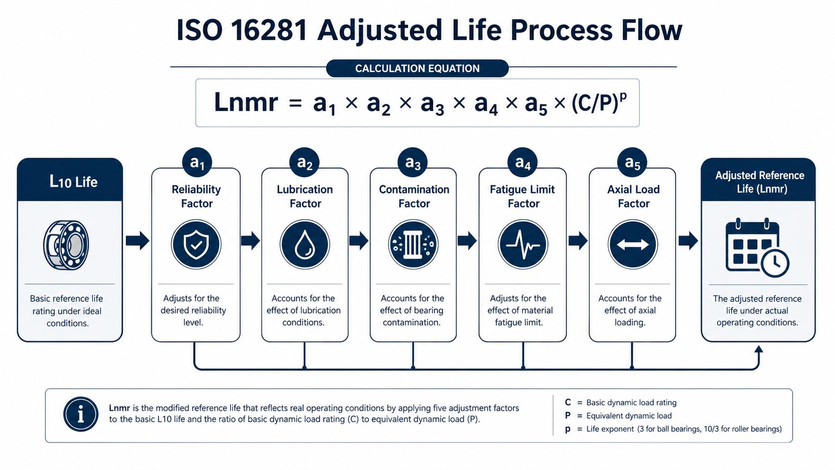
The ISO 281 result gives a starting point. ISO 16281 extends it by accounting for operating conditions that change stress inside the bearing:
Lnmr = a1 × a2 × a3 × a4 × a5 × (C/P)^p
These factors require the reliability review to document how the bearing is loaded, lubricated, contaminated, aligned, and fitted in the machine. That record matters when a pump, motor, or gearbox produces a life estimate far different from field experience.
What the factors represent
a1 is the reliability factor. For the ball-bearing targets discussed earlier, L10 uses 1.0, L5 uses approximately 0.62, and L1 uses approximately 0.21.
a2 is the lubrication factor. It combines the lambda ratio, which compares lubricant film thickness with surface roughness, and the viscosity ratio, which compares actual viscosity at operating temperature with the recommended reference condition. If operating viscosity falls below the recommended k1 × ν1 reference, a2 can fall below 1.
a3 is the contamination factor. It reflects particle ingress and cleanliness, with the stated typical range of 0.2 to 0.8. A sealed gearbox in a clean room may support a different selection from a dusty conveyor drive or washdown pump.
ISO 16281:2025 also addresses fatigue load limit, tilting or misalignment, operating clearance, and internal load distribution within its modified reference-life framework, as described in the ISO 16281:2025 technical reference. Apply the relevant catalogue data and standard method to the bearing arrangement. Do not treat every factor as a generic multiplier.
Gearbox example
A gearbox input-shaft bearing has an original ISO 281 L10 of 25,000 hours. The target is L5, giving a1 = 0.62. The lubrication review gives a2 = 0.7, associated with a lambda ratio of 1.2, and the contamination review assigns a3 = 0.5 for typical cleanliness.
Using those three modifiers:
Lnmr = 0.62 × 0.7 × 0.5 × 25,000
Lnmr = 5,425 hours
Treat this value as an adjusted reference life tied to the stated assumptions. Each modifier should be traceable to a catalogue table, laboratory curve, lubricant evaluation, cleanliness assessment, or documented operating condition.
A bearing with this result does not automatically justify a larger replacement. Check oil viscosity at temperature, filtration, breather condition, seal effectiveness, gear-generated thrust, shaft alignment, and load spectrum first. The misalignment review for rotating shafts explains why adequate catalogue capacity can still accompany uneven internal loading.
Matching the Right Life Model to the Application
No single life model fits every asset. The basic ISO 281 result works well as an ideal-condition benchmark. ISO 16281 modified reference life is more useful when an operating asset has known lubrication, contamination, clearance, alignment, and load-distribution conditions. An extended stress model is more appropriate when a machine runs through a variable loading spectrum, such as a VFD-driven pump or conveyor.
Decision table for plant equipment
| Application | Dominant Failure Mode | Recommended Life Model |
|---|---|---|
| Greenfield motor specification | Rolling-contact fatigue under defined design load | ISO 281 for initial sizing and vendor acceptance |
| Operating centrifugal pump | Contamination, water ingress, lubrication degradation, misalignment | ISO 16281 modified reference life with condition verification |
| Gearbox input shaft | Combined radial and axial loading, lubricant film weakness, internal load distribution | ISO 16281, with catalogue factors and load review |
| VFD-driven conveyor | Variable load and changing speed across the duty cycle | Extended stress model for variable loading spectra |
| Standby compressor | False brinelling and vibration-induced fretting while idle | Preservation and storage assessment, not ISO 281 alone |
| Transported pump assembly | Fretting corrosion, false brinelling, shock, and vibration | Transport controls plus static and preservation review |
| Slow oscillating mechanism | Micro-motion damage and lubricant film collapse | Application-specific low-speed analysis |
The standard life calculation has limits at low speed and isn't suitable for every stationary or oscillatory condition, as discussed in this bearing life calculation reference. At very low motion, rolling-contact fatigue may not control the failure. The bearing can develop false brinelling, which occurs when a stationary bearing experiences vibration or oscillation. Fretting corrosion can then remove material through repeated micro-motion.
Standby equipment requires a different question
A spare pump may have accumulated almost no running hours and still fail during commissioning. Nearby machinery can transmit vibration through the base, transport can impose shocks, and an unrotated shaft can leave repetitive contact marks in the raceway. A classical fatigue-life number won't represent that damage mechanism.
For standby assets, the practical controls include shaft rotation where appropriate, vibration isolation, suitable grease management, controlled storage, and transport restraints. The inspection should look for raceway marks, reddish-brown fretting debris, lubricant separation, corrosion, and seal damage before the asset is returned to service.
The decision is therefore not “Which bearing has the highest calculated hours?” It is “Which damage mechanism is active when this bearing is running, idle, transported, or exposed to the plant environment?”
Turning Bearing Life Numbers Into Maintenance Strategy
A life calculation becomes valuable only when it changes a maintenance action. For a critical pump, the adjusted reference life should influence lubrication planning, vibration routes, spare preservation, inspection timing, and the evidence required before extending an interval.
Set actions from the adjusted result
Relubrication intervals should be based on 20% to 30% of L10a, rather than copied from a generic chart. The calculation should use the adjusted life appropriate to the application, then be checked against grease type, bearing speed, temperature, sealing, water exposure, and replenishment quantity.
Vibration analysis trending should begin at 60% of L10a when no criticality premium applies. That isn't a substitute for earlier commissioning measurements. A baseline should be captured after installation, then compared with later spectra for changes in defect frequencies, looseness, imbalance, misalignment, and lubrication condition.
Spare bearings for standby pumps should be preserved in nitrogen-purged foil wrap to limit oxidation-driven false brinelling. The storage procedure also needs controlled handling, shaft support, vibration isolation, stock rotation, and a pre-installation inspection.
Maintenance decision: If the adjusted life changes because contamination or lubrication factors changed, the maintenance interval must change with it. Copying the old interval preserves the old assumption, not the new evidence.
Build a traceable plan
Condition monitoring thresholds should be tied to the applicable ISO 51962 broadband velocity limits, scaled by bearing bore and equipment context. The plant should document the a_iso factors, catalogue tables, load assumptions, lubricant grade, and cleanliness basis used for each critical bearing.
A practical plan can look like this:
| Maintenance Task | Interval (% of L10a) | Trigger Threshold | Responsible Role |
|---|---|---|---|
| Relubrication review | 20% to 30% | Grease condition, temperature, or lubricant evidence indicates deterioration | Reliability engineer and lubrication technician |
| Vibration trend review | 60% when no criticality premium applies | Applicable ISO 51962 broadband velocity limit, bearing-bore context, and spectral change | Vibration analyst |
| Standby bearing preservation inspection | Storage schedule based on asset risk | Corrosion, fretting marks, seal damage, or storage-condition deviation | Maintenance planner |
| Life-model reassessment | At operating or process change | New speed, load, temperature, contamination, alignment, or lubricant condition | Reliability engineer |
| Failure review | After every bearing replacement | Evidence of contamination, installation error, electrical damage, misalignment, or overload | Maintenance supervisor and reliability team |
For larger programs, route-based and continuous monitoring can be combined with oil analysis, thermography, ultrasound, and motor current analysis. A bearing trend should never stand alone when the machine is a pump, motor, gearbox, or conveyor with several possible forcing functions.
The maintenance team can use predictive maintenance for bearing systems to structure inspection routes and escalation rules around actual failure modes. Forge Reliability can be included in that work once the plant has identified its critical assets, data gaps, and recurring bearing failures.
The final review question is simple: does the recorded interval reflect the current a_iso factors and operating evidence? If not, the plant is managing a historical calculation rather than the equipment in front of it.
Forge Reliability offers predictive maintenance, condition monitoring, and reliability consulting for pumps, motors, gearboxes, conveyors, and other critical rotating equipment. Request a free reliability assessment through Forge Reliability to review bearing-life assumptions, failure modes, monitoring practices, and maintenance intervals across the plant fleet.