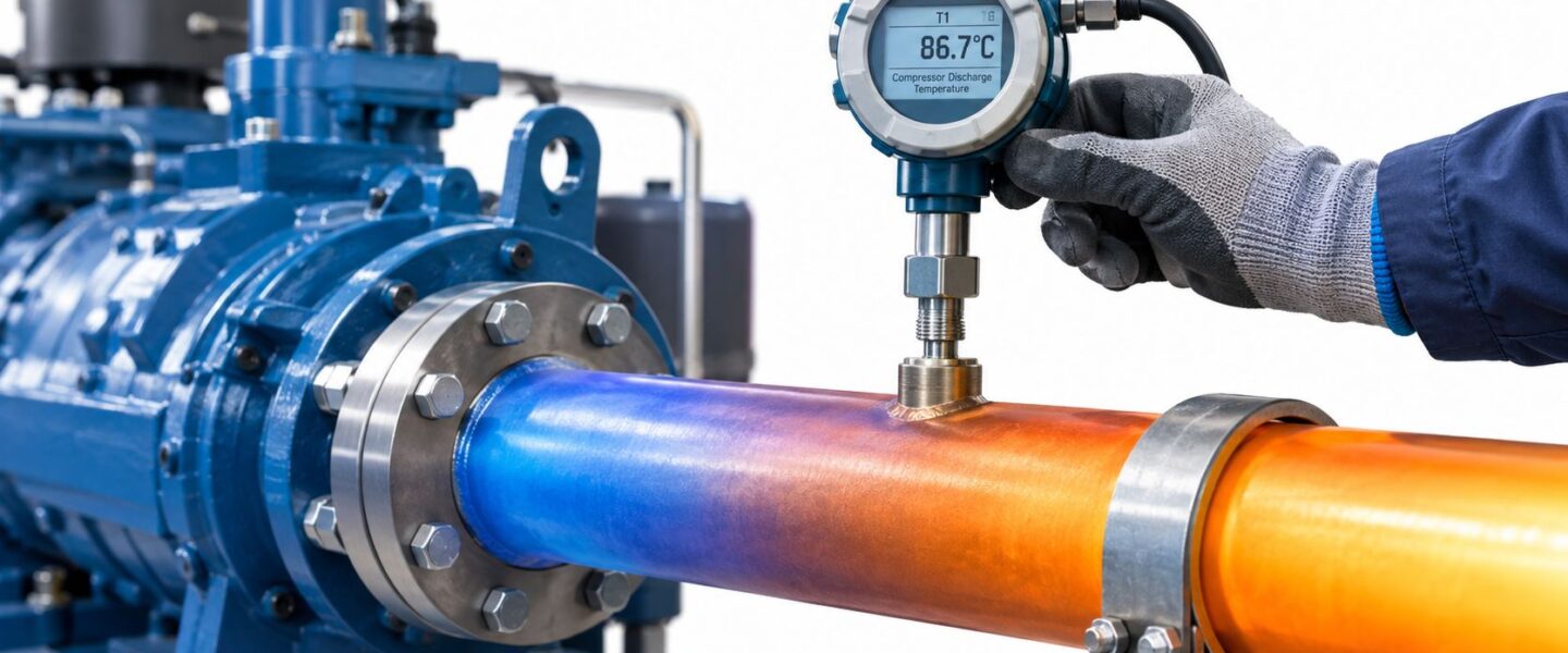
A compressor can look healthy on the morning shift and still be moving toward an oil failure. The first visible clue is often a discharge temperature trend that rises while production continues, followed by a thermal trip, darkened lubricant, valve damage, or an unexpected shutdown. By the time the alarm reaches the control room, the compressor may already have experienced damaging internal heat.
For reliability engineers, maintenance managers, and plant operations leaders, compressor discharge temperature is more than an efficiency reading. It connects compression ratio, refrigerant or gas conditions, lubrication, sealing, materials, and process control. The right interpretation helps a team decide whether to correct charge and airflow, inspect a cooler, change an alarm limit, or leave a deliberately warm process untouched because dew-point control requires it.
A food and beverage facility, for example, may see a refrigeration screw compressor run hotter as evaporating conditions fall. That rise can indicate restricted refrigerant flow or excessive superheat, but a gas compressor at a wellhead may need to remain above the process-gas dew point to prevent condensation. The number only becomes useful when the service, measurement location, and failure mechanism are understood.
This guide develops that judgment from the plant floor upward. It explains how temperature is created, why readings run high or low, how to instrument the point correctly, how service-specific limits should be set, and how trending turns a single alarm into a predictive maintenance decision. A broader industrial compressor maintenance guide can support teams building the surrounding maintenance program.
Table of Contents
- Introduction Why Compressor Discharge Temperature Matters on the Plant Floor
- What Compressor Discharge Temperature Is and How It Is Created
- Why Discharge Temperature Runs High or Low and What It Signals
- How to Measure and Instrument Discharge Temperature Correctly
- Acceptable Ranges Thresholds and How to Set Alarms by Equipment Type
- Monitoring Trending and Diagnostic Workflow for Predictive Maintenance
- Maintenance and Mitigation Actions That Keep Discharge Temperature in Control
Introduction Why Compressor Discharge Temperature Matters on the Plant Floor
A maintenance supervisor receives a high-temperature alarm during production. The compressor continues carrying load, but its discharge reading has climbed steadily. Operators also notice darker oil in the sight glass and a cooler outlet warmer than on the previous shift. The machine is still running, yet the evidence points toward a changing thermal condition.
A rising discharge temperature is an early reliability signal, not merely a value to reset. In refrigeration service, application guidance commonly treats about 225°F as a warning level, 250°F as a danger level, and 275°F as a failure condition for discharge-line temperature. The same guidance states that discharge temperature should not exceed 280°F or fall below 200°F (Copeland application guidance). These figures are service-specific reference points, not universal operating targets. They show why alarm response must be based on equipment design and operating duty.
The temperature is a reliability signal
Excess heat can degrade lubricant, shorten seal life, and accelerate valve wear. A discharge-line reading above 225°F may correspond to an internal compressor temperature above 300°F, a range where oil breakdown begins, according to manufacturer discharge-temperature guidance (Copeland discharge-temperature guidance).
The plant team must identify the source of the heat. Possible causes include low suction pressure, high superheat, poor heat rejection, a restriction, or a high compression ratio. The same temperature can also be intentional when process gas must remain above its dew point. In that service, reducing temperature without checking the process objective could create condensation, liquid carryover, or downstream corrosion risk.
The operating example
In a food and beverage refrigeration plant, low evaporating temperature can increase the compression burden on a screw compressor. If discharge temperature rises while suction pressure falls and superheat increases, the reliability team should inspect refrigerant control and airflow before the compressor reaches a thermal trip.
An oil and gas gathering system may require a warm discharge instead. Keeping gas above the process-gas dew point helps prevent condensation downstream. Discharge temperature sits at the intersection of thermodynamics, oil health, and uptime. The correct response depends on whether the reading represents heat damage or deliberate dew-point control.
Teams building the surrounding maintenance program can use this industrial compressor maintenance guide to connect temperature decisions with inspection, lubrication, and reliability practices.
What Compressor Discharge Temperature Is and How It Is Created
A technician checks a compressor and finds the discharge pipe hotter than expected. The reading may indicate excessive heat, yet a warm discharge can also be deliberate when the process must keep gas above its dew point. The first task is to understand what the temperature represents before changing the setpoint or reducing the load.
Gas heats during compression because mechanical work transfers energy into it. A bicycle pump shows the effect clearly. Repeatedly compressing air warms the pump barrel because energy moves into both the air and the surrounding metal.
An industrial compressor follows the same principle. It draws gas in at suction pressure, reduces its volume, and delivers it at higher discharge pressure. A larger pressure increase requires more work, so the discharge gas generally leaves hotter.
Three terms operators need
Compression ratio compares discharge pressure with suction pressure. Low suction pressure or high discharge pressure raises the ratio and usually increases discharge temperature.
Superheat is the temperature of a vapor above its boiling or saturation temperature at a given pressure. In refrigeration, high suction superheat means hotter vapor enters the compressor. The returning refrigerant then provides less cooling to the machine.
Discharge temperature is usually the temperature measured on the discharge line after gas leaves the compressor. It is a practical field reading, not necessarily the hottest temperature inside the machine.
The discharge valve port is commonly hotter than the pipe. A discharge-line sensor mounted within 6 inches of the outlet can read 50°F to 75°F cooler than the valve port, according to manufacturer application guidance. That difference matters because an acceptable line reading may hide a higher temperature at the valve plate, where oil carbonization and lubricant breakdown can occur.
How cooling changes the final reading
The outlet temperature reflects several conditions at once. More compression work and higher suction superheat raise it. Ambient conditions, cooler performance, refrigerant selection, gas composition, process load, and injection or intercooling controls also affect the final reading.
A centrifugal compressor can show a different thermal response from a refrigeration screw compressor, so its monitoring approach should follow the machine's design. Teams working across rotating equipment can review guidance on centrifugal compressors before applying a generic alarm.
The practical rule is straightforward. A line temperature is a useful proxy, not a direct measurement of the hottest internal component. Set each alarm with the sensor location in mind, then decide whether the limit protects against heat damage or maintains the process gas above its dew point.
Why Discharge Temperature Runs High or Low and What It Signals
A compressor can trip on a hot afternoon, yet the same discharge temperature may be acceptable on a gas-gathering system. The reading becomes useful only after the team asks two questions: Is heat damaging the machine, or is temperature being maintained to keep the process gas dry? That distinction determines whether operators reduce thermal load or protect a dew-point margin.
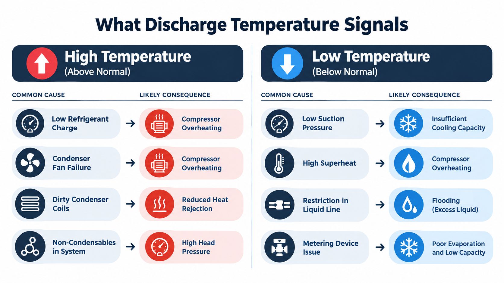
High discharge temperature usually means the compressor is facing excessive thermal work or cannot reject heat effectively. Common causes include low refrigerant charge, high superheat, restricted airflow, metering-device restrictions, high compression ratio, and fouled coolers. Each cause points to a different inspection path.
Low charge can lower suction pressure and starve the evaporator. A restricted metering device can create the same low-suction symptom even when the charge is correct. A dirty condenser, failed fan, or non-condensable gas can raise condensing pressure, forcing the compressor to do more compression work.
High temperature has several failure mechanisms
Lubricant is often the first material at risk. As temperature increases, oil viscosity and chemical stability can decline. The protective oil film then becomes less effective around bearings, seals, and other moving surfaces. Continued overheating can accelerate valve wear and shorten seal life.
A fouled cooler follows a different failure path. The compressor may be mechanically sound, while poor heat transfer leaves the oil or discharge gas too hot. For a process compressor, the inspection should include cooler fouling, intercooling, aftercooling, suction conditions, and compression ratio. Adjusting a refrigeration charge would not address every process-compression problem.
Practical rule: A high reading identifies thermal stress, not its root cause. Interpret pressure, superheat, oil condition, airflow, and cooler performance together.
Low temperature can also signal risk
Low discharge temperature may result from overcooling, liquid carryover, excessive liquid injection, or a control fault. In refrigeration, liquid returning to the compressor can dilute oil and weaken lubrication. In gas compression, a temperature that is too low can permit condensation when the process requires gas to remain above its dew point.
Dew point is the temperature at which gas components begin condensing at a given pressure and composition. Guidance for some compressor services calls for discharge temperature to remain at least 10 K, or 18°F, above process-gas dew point, while some natural-gas wellhead guidance uses a 30°F to 40°F margin (API guidance on discharge temperature and dew point).
That margin explains why a reading near 250°F to 280°F may be normal in an oil and gas wellhead gathering system. The compressor may be maintaining enough heat to prevent downstream condensation. The same reading could indicate severe trouble in a refrigeration system. Lowering temperature without checking gas composition and condensation risk can cause liquid carryover, oil dilution, or corrosion.
For recurring trips, a structured compressor troubleshooting process helps separate a genuine thermal excursion from a faulty sensor, poor mounting, or an alarm configured for the wrong service.
How to Measure and Instrument Discharge Temperature Correctly
A compressor can be operating normally while a poorly installed sensor reports a false alarm. The reverse is more dangerous: a weak measurement can hide overheating. The instrument must represent the compressor outlet condition while limiting ambient heat loss and electrical noise.
Place the sensor where the decision is made
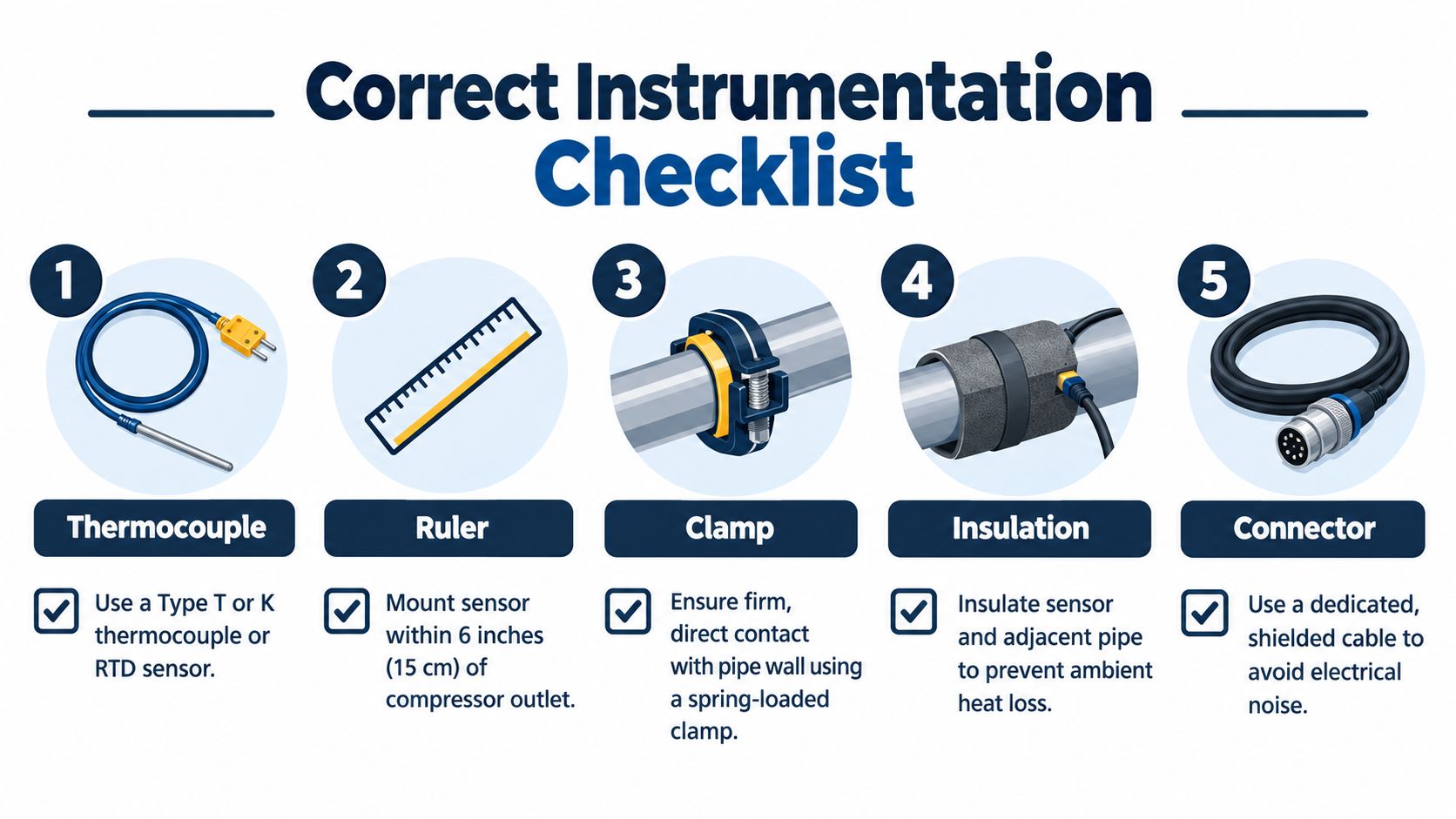
Manufacturer guidance identifies the discharge line within 6 inches of the outlet as a typical measurement location. A valve port may read 50°F to 75°F hotter than the line, so the two readings should not be treated as interchangeable. A sensor installed far downstream may measure gas after it has cooled, rather than the compressor's actual thermal condition.
Select a thermocouple or RTD suited to the service. Clamp it firmly to clean pipe metal, then insulate the sensor and nearby pipe. Good contact is like placing a thermometer against the skin instead of holding it in the air. A loose clamp responds slowly and may follow ambient temperature rather than the pipe.
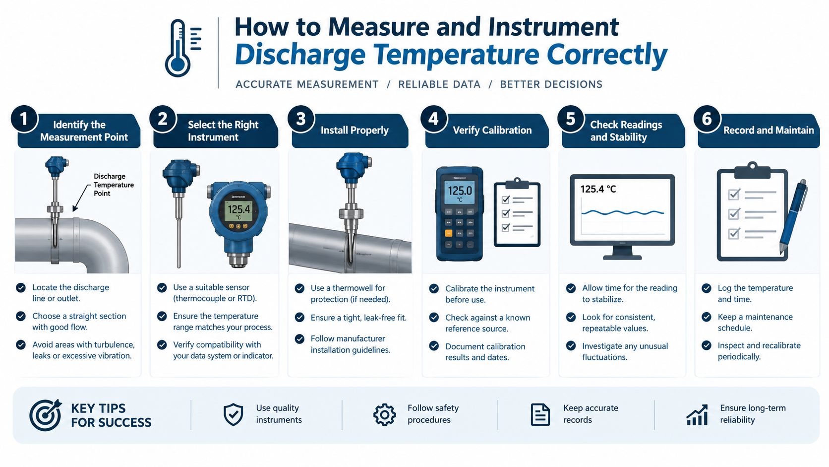
A field verification routine
During route inspections or continuous-monitoring installation, verify each part of the measurement path:
- Sensor type: Confirm that the thermocouple or RTD suits the temperature range and service.
- Physical location: Measure the distance from the compressor outlet and record it in the asset data.
- Mechanical contact: Check that the clamp is tight and the pipe surface is clean.
- Thermal insulation: Look for missing or damaged insulation around the sensor.
- Signal integrity: Confirm dedicated, shielded wiring and inspect connectors for damage.
- Calibration confidence: Compare the installed channel with a calibrated reference under controlled operating conditions.
A chemical processing plant with a screw compressor may need both a fast protective channel and a historian trend. The protective channel should trip at the OEM limit, while the historian retains discharge temperature with load and ambient conditions. A broader equipment dashboard can also use the disk monitoring features overview as a model for combining health and temperature data.
Temperature becomes more useful when read with vibration, oil analysis, and thermography. A condition monitoring systems resource can help planners organize these channels for route-based and continuous monitoring. No single sensor proves the cause of a problem. Confirm the reading, compare it with operating conditions, and then decide whether the temperature reflects intentional dew-point control or developing equipment trouble.
Acceptable Ranges Thresholds and How to Set Alarms by Equipment Type
A discharge temperature that is healthy for one machine can damage another. Compressor type, refrigerant or process gas, oil system, seals, cooling arrangement, compression stages, and dew-point requirements all shape the allowable window. The alarm target is therefore a service decision, not a universal number.
Use published values as reference points, then confirm them against the equipment manual and operating case. The table also separates two different questions: whether the temperature is high enough to damage components, and whether it is high enough to keep condensed liquid out of the discharge system.
Typical Discharge Temperature Limits by Service
| Equipment and Service | Normal Range | Warning and Shutdown Guidance |
|---|---|---|
| Refrigeration and HVAC discharge line | Around 200°F to 225°F is generally preferred for reasonable life expectancy | About 225°F is a warning level, 250°F a danger level, and 275°F a failure-condition range. Some manufacturer guidance states that discharge temperature should never exceed 280°F or fall below 200°F. |
| Refrigeration and oil-injected screw service | About 170°F to 180°F normal discharge temperature | Oil cooling may be required to keep oil around 120°F to 140°F. See the industrial refrigeration oil-cooling requirements for the relationship between oil temperature and compressor operation. |
| Rotary compressor | Manufacturer maximum of 127°C | Use the manufacturer's limit and protective logic. Rotary compressor guidance provides an example of a service-specific maximum. |
| Two-stage variable-frequency heat pump | High-pressure-stage discharge below 120°C for reliable operation in the cited study | Single-stage compression reached 130°C at an evaporating temperature of -15°C, described as harmful to the compressor. This comparison shows why stage arrangement and operating condition belong in the alarm basis. |
| Industrial gas compressor | Service-specific | Above about 350°F, or 177°C, cooling is recommended because materials, seals, and running clearances can be damaged. An engineering reference on discharge temperature provides the cited context. |
| Natural-gas wellhead service | Can be intentionally hot, depending on gas composition and dew point | Maintain the applicable dew-point margin, often at least 30°F to 40°F above dew point in some operating guidance. The temperature may be intentionally high when it prevents condensation, but the required margin must match the service basis. |
Alarm logic must follow the service
A process-gas compressor in a pulp and paper plant should not inherit a refrigeration alarm. Set a normal operating band, warning threshold, shutdown threshold, and minimum dew-point margin where condensation is possible. Define which signal initiates the shutdown and whether the alarm acts immediately or after a confirmed delay.
For ammonia or comparable refrigeration duty, public guidance commonly places normal operation around 90°C to 130°C, with alarm and shutdown points around 145°C to 155°C for some configurations. Check those values against the actual compressor and refrigerant before applying them.
A semi-hermetic compressor service manual for A2L and A1 applications gives a discharge-line limit of 120°C, measured a few centimeters from the service valve. It states that exceeding the maximum requires discharge-temperature control to stop the compressor (semi-hermetic compressor service guidance). The alarm record should identify sensor location, service, limit, and shutdown authority. A hot reading can indicate heat damage risk, or it can be the condition keeping the line above its dew point. The control strategy must distinguish between those cases.
Monitoring Trending and Diagnostic Workflow for Predictive Maintenance
A single discharge reading answers only one question: what temperature exists at one location now? A trend answers a more valuable question: how is the compressor's thermal behavior changing under comparable load and ambient conditions?
Reliability teams should trend discharge temperature with suction pressure, discharge pressure, superheat, oil temperature, vibration, load, and cooling-system status. The relationship between channels often reveals the cause. A rising temperature with falling suction pressure points toward a different investigation from a rising temperature with stable pressure and worsening vibration.
A high-temperature workflow
A power generation site with a turbine-driven compressor can use the following sequence during a high-temperature event:
- Validate the measurement. Compare the control-system value with a calibrated handheld reference and inspect sensor contact, insulation, wiring, and location.
- Check the pressure relationship. Review suction and discharge pressure to determine whether compression ratio has increased.
- Review superheat and load. High superheat may indicate a refrigerant-control problem or an operating condition that is sending excessively hot gas into the compressor.
- Inspect heat rejection. Check cooler fouling, airflow, fan operation, filters, intercooling, aftercooling, and oil-cooling response.
- Evaluate lubrication. Review oil temperature, level, appearance, analysis results, separator performance, and signs of oil dilution or degradation.
- Confirm the operating envelope. Compare the reading with the OEM limit and determine whether the process requires a dew-point margin.

Alarm design should support diagnosis
A shutdown limit protects the machine, but an earlier warning gives maintenance time to act. Teams can combine an absolute temperature alarm with a rate-of-change alert, a high-temperature duration rule, and correlation rules that compare temperature with pressure, load, and oil conditions.
A low-temperature alert deserves equal attention where condensation is hazardous. The diagnostic path should check dew point, gas composition, liquid carryover, injection controls, oil dilution, and downstream separator performance before anyone lowers the temperature target further.
The resulting logic belongs in the asset FMEA, RCM analysis, and condition-monitoring route. The failure mode is not “high temperature.” It may be loss of condenser airflow, cooler fouling, high compression ratio, degraded oil, failed metering control, or loss of dew-point margin. Each cause needs an owner, an inspection method, and a defined response.
Maintenance and Mitigation Actions That Keep Discharge Temperature in Control
Temperature control starts with the physical causes of thermal stress, not repeated alarm resets. Maintenance planners should verify charge and superheat, clean condensers and coolers, check airflow, inspect metering devices, and look for filter restrictions. They should also confirm oil injection and cooling controls. Process compressors may require lower compression ratio, better intercooling or aftercooling, staged compression, or corrected suction conditions.
Prevention needs operating context
Oil cooling needs the right balance. Normal rotary-screw discharge may sit around 170°F to 180°F, while oil may need to remain around 120°F to 140°F. Excessive cooling can create condensation, oil foaming, poor separator performance, or inefficient control. A hot reading is therefore not automatically a fault, especially when temperature protects the process dew-point margin. It becomes a failure signal when it exceeds the service limit or rises with worsening load, pressure, oil condition, or cooling performance.
A documented industrial compressor maintenance program should connect alarm review with work orders, oil analysis, thermography, vibration data, and root-cause analysis. Teams standardizing procedures and operator records can use a practical help centre to support consistent task instructions and knowledge capture.
Maintenance position: Protect the compressor from excessive heat, but do not lower temperature blindly. The target must protect oil, seals, materials, and the process dew-point margin together.
Use five controls:
- Correct the cause: Restore refrigerant control, airflow, cooler performance, and suction conditions.
- Protect the lubricant: Verify oil temperature, circulation, injection, separator performance, and oil condition.
- Set service-specific limits: Use OEM instructions, gas composition, ambient conditions, and dew point.
- Trend the change: Compare discharge temperature with load and related condition indicators.
- Escalate repeated excursions: Treat recurring alarms as a reliability problem, not an operator nuisance.
Forge Reliability can assess discharge-temperature monitoring, thermography, oil analysis, vibration, and condition-monitoring coverage across critical rotating assets. Plant teams with 20 or more critical assets can visit Forge Reliability to request a free reliability assessment, with a stated 24-hour response and predictive-maintenance support.