A packaging line can report 100% connectivity and still leave the maintenance team guessing. The PLC exchanges tags, SCADA displays trends, and a new dashboard highlights vibration readings. Then a conveyor motor trips, the alarm points to an unfamiliar tag, timestamps don't align with the historian, and no condition-monitoring alert creates a useful CMMS work order. The integration is technically online, but operationally unreliable.
That gap defines modern automation system integration. Industrial plants aren't connecting isolated machines anymore. In 2023, manufacturers installed 541,302 industrial robots worldwide, while the operating base exceeded 4.28 million robots, approximately 10% higher than the prior year. International Federation of Robotics data shows why integration now involves robots, PLCs, motion control, machine vision, safety systems, industrial networks, and plant-level data. The engineering question is no longer whether devices can communicate. It's whether the resulting information remains trustworthy when a bearing deteriorates, a sensor drifts, or a control server fails.
Table of Contents
- The Hidden Cost of Poor Integration Context
- Staged Methodology for Integration Scoping
- Architecting the Control and Data Layer
- Data Governance and Tag Mapping Strategies
- Cybersecurity and Network Segmentation
- Testing, Commissioning, and Change Management
- Measuring ROI and Driving Continuous Improvement
The Hidden Cost of Poor Integration Context
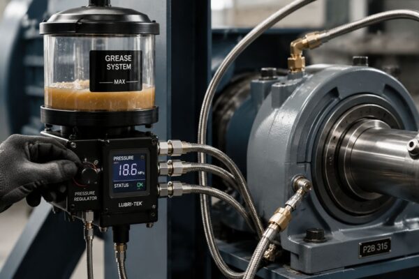
A food and beverage plant recently automated a bottle-packaging line with robotic case handling, servo conveyors, photoelectric sensors, and a supervisory control system. Commissioning succeeded because every controller exchanged data and operators could see the line status. The reliability team discovered the core issue later: one motor appeared as MTR_204, another as CV07_DRV, and the vibration gateway used a third identifier for the same asset.
The timestamps created another failure path. Controller events, historian samples, and vibration records arrived with different time references, so a short speed change looked like a developing mechanical fault. When the team found elevated vibration on a gearbox, the condition-monitoring platform couldn't connect the observation to the correct equipment hierarchy or create a work order with the relevant failure mode. The dashboard contained data, but it didn't preserve context.
Connectivity isn't the same as maintainability
A reliable integration must answer basic maintenance questions immediately:
- What asset generated the signal? The tag must resolve to a unique physical device, location, parent assembly, and service function.
- When did the event occur? Controllers, gateways, historians, and work-order systems need a consistent time basis.
- What does the signal mean? Units, operating state, sensor position, alarm limits, and data quality must travel with the value.
- What action follows? A high vibration reading needs an owner, a defined response, and a traceable maintenance record.
The scale of deployment makes these weaknesses expensive. In 2024, approximately 542,000 industrial robots were installed globally, and the worldwide operational stock reached 4,664,000 robots, a 9% increase from 2023, according to the International Federation of Robotics. Every additional cell adds more reducers, servo motors, encoders, cable carriers, tooling, safety circuits, and network dependencies that maintenance teams must diagnose over the asset lifecycle.
A dashboard-first project often fails because it starts with visual display instead of data qualification. The same applies to an AI pilot. If a vibration channel is poorly mounted, failure labels are inconsistent, or a historian stores stale values without marking them, automation can increase false alarms and weaken operator trust. A criticality-ranked OEE improvement approach should therefore include tag quality, alarm behavior, and work-order traceability, not just production reporting.
For plants selecting external support, the decision also includes ownership of infrastructure, identity management, endpoint support, and legacy-system knowledge. Guidance on choosing a manufacturing IT partner can help operations leaders define those responsibilities before a connectivity project creates another unsupported layer.
Staged Methodology for Integration Scoping
Automation integration should begin with the failure consequences the plant needs to control, not with a preferred protocol or dashboard. A controlled scope keeps reliability, operations, engineering, cybersecurity, and maintenance planning aligned from the first workshop.
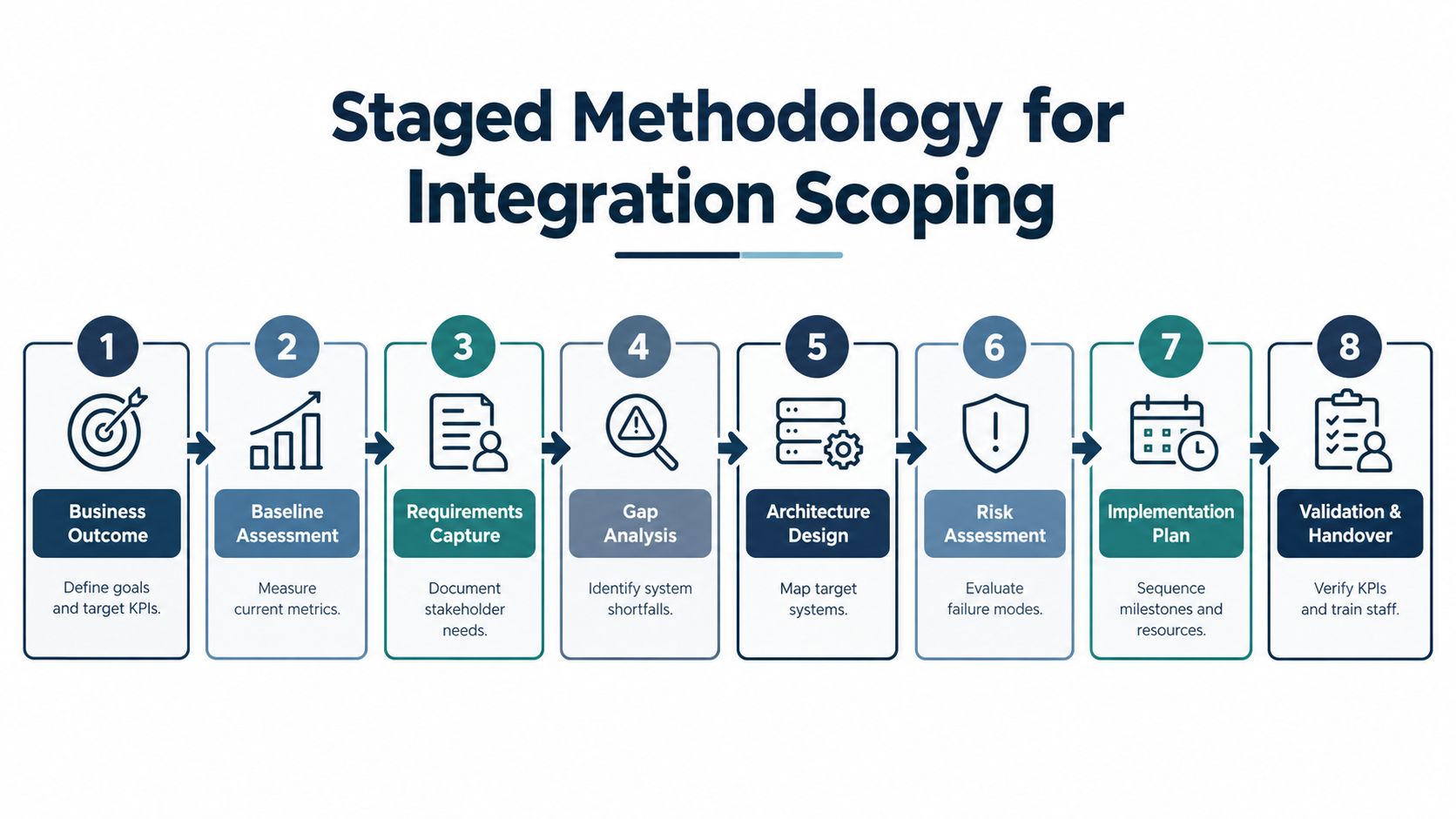
Eight stages that prevent rework
Define the business outcome. Choose the operational result first, such as higher OEE, more stable throughput, shorter changeovers, lower energy intensity, or less unplanned downtime. Each target needs a named owner and a measurement method.
Establish the baseline. Record current production behavior before changing the system. Include downtime categories, recurring failure modes, maintenance response, alarm frequency, data gaps, and the quality of existing equipment records. Without a baseline, the project can show more data without proving more reliability.
Map the end-to-end process. Follow material, control decisions, inspections, operator actions, and maintenance interventions across the line. A packaging example might include filler, capper, labeler, conveyor, case packer, palletizer, and reject handling. Automating one bottleneck can move the constraint to another machine.
Inventory the technology and ownership. List PLCs, HMIs, SCADA servers, historians, MES connections, CMMS records, sensors, protocols, firmware, engineering workstations, remote gateways, and data owners. Capture unsupported devices and undocumented logic as project risks, not footnotes.
Rank interfaces and assets by criticality. A safety interlock, robot controller, and primary production drive don't deserve the same testing depth as a convenience dashboard. Rank each asset by production effect, safety consequence, repair time, redundancy, and diagnostic value.
Design the OT architecture. OT, or operational technology, is the hardware and software that monitors and controls physical processes. Define zones, permitted data flows, identity controls, secure remote access, backup ownership, firewall rules, and change approval before anyone opens a new path between systems.
Test representative failure modes. Use a test environment or controlled production window to simulate lost communications, stale data, sensor failure, invalid values, controller restart, historian outage, and CMMS integration errors. A successful tag exchange proves only that a normal message can travel.
Commission in stages and verify benefits. Start with a bounded area, train the operators and maintainers, resolve defects, and compare the measured result with the original baseline. Scale only after the acceptance criteria include diagnostics, fallback control, alarm quality, and maintenance workflow performance.
Avoiding pilot mode
Pilot mode happens when a plant proves that a small technology demonstration works but never establishes a repeatable engineering standard. McKinsey reports that 88% of heavy-industry respondents had begun or planned an automation transformation, yet only 4% reported significant bottom-line improvement. The same verified data reports 20–40% efficiency gains with positive ROI in 12–18 months for successful programs, but those outcomes depend on disciplined scaling, not on the presence of a pilot alone.
The scope should specify naming conventions, required metadata, alarm ownership, recovery responsibilities, training, and acceptance tests before procurement. Teams evaluating building custom system integrations should apply the same discipline to interfaces that they apply to mechanical and electrical design. A well-bounded project also supports maintenance cost reduction because it turns condition information into planned work instead of another stream for technicians to interpret manually.
Architecting the Control and Data Layer
The architecture must protect deterministic control while making useful information available to maintenance and business systems. Deterministic control means the controller performs a defined action within a predictable timing window. A historian, cloud gateway, or analytics application must never become a hidden dependency for a safety function or a basic local control loop.
Match each layer to its job
A PLC, or programmable logic controller, executes discrete machine logic, sequencing, interlocks, and fast responses. An RTU, or remote terminal unit, gathers and transmits field information, often across geographically distributed assets. A DCS, or distributed control system, coordinates continuous process regulation across control loops, such as temperature, pressure, and flow.
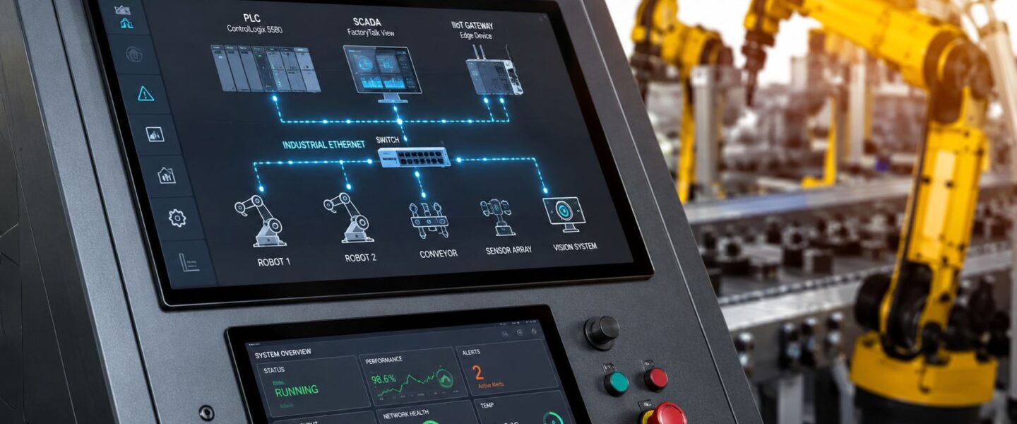
SCADA, meaning supervisory control and data acquisition, provides operator visualization, supervisory commands, alarms, and trends. It shouldn't replace the local logic that keeps a conveyor, pump, or reactor in a safe state. The historian stores time-series information for analysis, while MES connects production execution activities with plant and business processes.
Protocol selection should follow the data and failure requirements:
| Connection need | Practical fit | Reliability trade-off |
|---|---|---|
| Secure structured exchange between systems | OPC UA, an industrial communication framework with data modeling and security features | Strong context is possible, but certificate and identity administration must be owned |
| Simple device polling | Modbus | Broad compatibility, but limited native context means engineers must define units, quality, and naming separately |
| High-speed machine communication | Ethernet/IP | Useful in manufacturing environments, but network loading, controller capacity, and change control require testing |
Use gateways as boundaries, not shortcuts
An IIoT gateway can collect legacy signals and publish selected information to a modern historian or analytics service. The gateway should read from the control layer without inserting unnecessary write paths into deterministic logic. It should also buffer data during an upstream outage, mark stale values clearly, preserve timestamps, and expose health status to the maintenance team.
An automotive plant with dense robotic cells may need careful synchronization among robot motion, conveyors, vision inspections, and safety devices. A chemical facility has a different priority, stable process values, instrument calibration, shutdown logic, and controlled interaction with final control elements. The architecture must reflect the failure consequence, rather than copy a design from another industry.
Practical rule: Keep control local, move approved data outward, and make every gateway failure visible.
Network capacity isn't the only constraint. Controller scan time, historian write behavior, event buffering, clock synchronization, firmware compatibility, and diagnostic access can all affect maintainability. The architecture should document what happens when each layer disappears, including local control when SCADA is unavailable and safe behavior when a gateway stops forwarding data.
For rotating assets, the data layer must retain enough sampling context to distinguish a bearing defect from a load change or a process transient. A plant assessing condition-monitoring systems should specify sensor placement, operating-state references, data quality flags, and escalation paths alongside the network design.
Data Governance and Tag Mapping Strategies
The most difficult integration work often happens in spreadsheets, asset registers, and maintenance meetings rather than in the control cabinet. Data governance means assigning rules, owners, definitions, and quality checks to information throughout its lifecycle. Without it, the plant accumulates values that cannot support a defensible maintenance decision.
Build one asset identity
A motor should have one authoritative identity across the PLC, historian, CMMS, inspection route, spare-parts record, and equipment hierarchy. Tag normalization should define naming structure, location, parent asset, service, signal type, engineering unit, alarm state, and data owner. The identifier must survive a transmitter replacement, controller migration, or line rearrangement.
Time synchronization deserves equal attention. A speed change, overload, vibration peak, and operator response are useful only when their sequence is trustworthy. Engineers should test clock drift, daylight-saving behavior where applicable, gateway buffering, historian timestamps, and quality codes during commissioning.
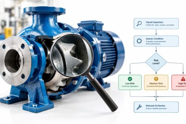
A criticality-ranked audit is more useful than attempting to clean every signal at once. Start with pumps, compressors, motors, gearboxes, VFDs, and turbines that can stop production or create a safety concern. For each asset, verify whether measurements are sufficiently reliable for the intended decision.
| Attribute | Requirement | Reliability impact |
|---|---|---|
| Asset identity | Unique identifier tied to the physical device and hierarchy | Prevents work orders and diagnoses from being assigned to the wrong equipment |
| Timestamp | Consistent time reference with documented synchronization behavior | Preserves event sequence during fault analysis |
| Measurement context | Units, sensor location, operating state, and quality status | Separates real deterioration from process changes or invalid data |
| Sampling behavior | Minimum sampling and transmission requirements defined by failure mode | Avoids missing transient faults or creating unusable data volume |
| Alarm definition | Rationalized limit, delay, severity, owner, and response | Reduces alarm floods and clarifies technician action |
| CMMS mapping | Condition finding linked to asset, failure mode, work type, parts, and labor | Turns detection into planned execution and closure evidence |
Reject bad signals early
A poorly mounted accelerometer can create misleading vibration patterns. An instrument that is rarely calibrated can produce stable-looking but wrong values. Inconsistent failure labels can make a model appear precise while teaching it the wrong relationship between symptoms and causes.
The integration should therefore validate completeness, latency, sensor drift, duplicate tags, impossible values, stale-data behavior, and CMMS closure quality. If a signal fails the acceptance rule, the system should mark it unavailable rather than presenting it as normal without notice.
The same principle applies to process-safety records. OSHA's mechanical-integrity requirements cover pressure vessels and storage tanks, piping and valves, relief and vent systems, emergency-shutdown systems, and controls such as sensors, alarms, and interlocks. OSHA process safety guidance requires written maintenance procedures, periodic inspection and testing, training, and correction of deficiencies before continued use or within a safe, timely period.
OSHA also requires inspection and test records to identify the date, performer, equipment identifier, procedure or description, and results, with supporting mechanical-integrity documentation retained for the process lifetime. OSHA documentation guidance makes asset identity a compliance issue as well as a reliability issue. A CMMS integration plan should preserve links between control tags, test procedures, work orders, and final results. A practical CMMS implementation guide for maintenance teams can help teams define those workflows before data enters production.
Cybersecurity and Network Segmentation
Cybersecurity belongs in the reliability case because a compromised or unavailable control path can stop production, suppress diagnostics, or create unsafe operating conditions. “More connected” isn't automatically more reliable. Every new remote connection, cloud historian, engineering workstation, and analytics gateway introduces ownership questions and failure modes.
Rockwell Automation's 2025 survey of 1,560 respondents across 17 major manufacturing countries reported that only 30% had fully integrated IT and OT security operations centers. The figure highlights an operational gap: many plants connect systems before they establish who monitors access, approves changes, restores configurations, or responds when a security control affects alarm availability.
Segment by consequence
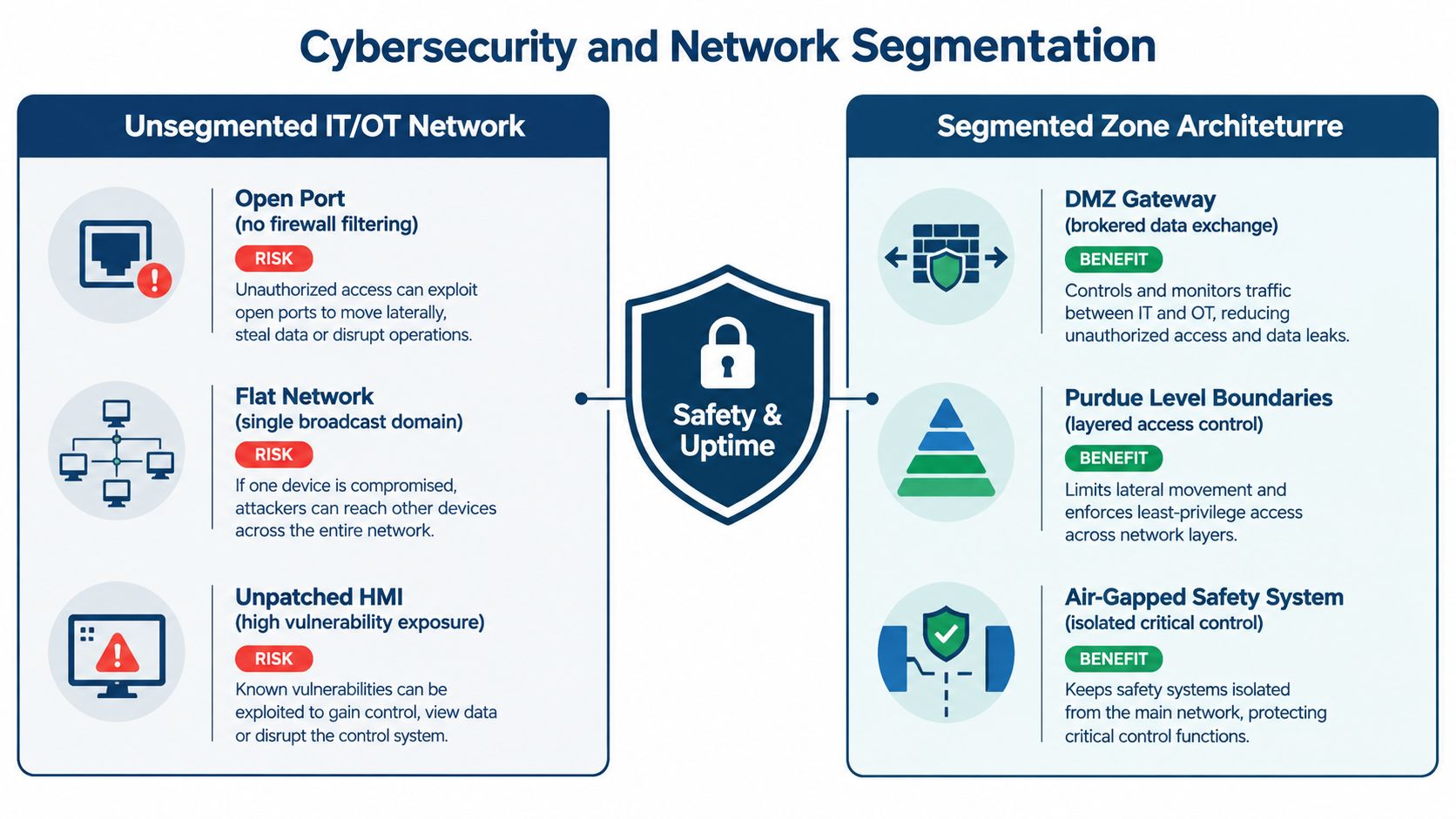
The Purdue model separates industrial-control-system networks from enterprise networks and the internet. NIST defines segmentation as partitioning a network into smaller security domains or enclaves governed by appropriate authority, policy, and trust levels. NIST guidance for industrial control systems supports a design in which enterprise IT, plant supervisory systems, manufacturing operations, controller networks, and safety systems have controlled relationships rather than unrestricted access.
A segmented packaging line might place business applications outside a plant boundary, exchange approved data through a demilitarized zone, isolate supervisory servers from controller networks, and keep safety systems under stricter access rules. The reliability benefit is containment. A compromised business workstation has fewer direct paths to PLC logic, HMI servers, or safety controllers.
Make access and recovery operational
Use least privilege, meaning each person or service receives only the access required for its defined task. Vendor access should be approved, time-limited, logged, and removed when the work ends. Offline recovery copies should include PLC programs, HMI configurations, historian settings, network documentation, and CMMS integration mappings, with restoration tested rather than assumed.
NIST's OT guidance emphasizes preserving performance, reliability, and safety while applying controls such as anomaly detection, application allowlisting, file-integrity checking, controlled changes, and authenticated authorization. Those controls need maintenance ownership. A blocked diagnostic connection during a bearing investigation can delay a decision, while an uncontrolled connection can expose the plant to a larger failure.
Reliability test: Disable the monitoring path without affecting control, then prove that operators can recognize the loss, maintain safe operation, and restore trusted data.
Teams working with a PLC with SCADA should document permitted communications, firewall ownership, alarm behavior during isolation, and the recovery path for controller configuration. Cybersecurity is complete only when the plant can operate, diagnose, and recover under abnormal conditions.
Testing, Commissioning, and Change Management
A data pipeline that passes normal tags has not proved operational readiness. Commissioning should test what happens when the data is late, wrong, missing, duplicated, or disconnected.
Test failure behavior before production release
A representative test environment or controlled maintenance window should cover:
- Communication loss: Disconnect the gateway or network path and verify local control, alarm annunciation, event logging, and recovery.
- Stale data: Stop a source value without forcing it to zero. Confirm that the receiving system marks the value stale instead of treating the last reading as current.
- Alarm quality: Test limits, delays, priorities, shelving rules, ownership, and response instructions. Remove alarms that don't lead to a defined action.
- Historian integrity: Compare source events with stored timestamps, quality codes, sequence of events, and buffered data after reconnection.
- CMMS workflow: Confirm that a validated condition finding creates the correct asset record, failure mode, recommendation, required parts, labor estimate, and approval path.
- Fallback control: Stop the SCADA or historian service and verify that the machine or process remains controllable locally where the design requires it.
- Safety functions: For hazardous chemical processes, include sensors, alarms, interlocks, emergency-shutdown logic, and final control elements within the test scope.
For safety-instrumented systems, proof-test frequency should be based on PFDavg, the average probability that a safety function fails when demanded, rather than a calendar habit. IEC 61511 requires testing the complete safety-instrumented function, including sensor, logic solver, and final element. The proof-testing guidance explains why dangerous-undetected failure rates and test intervals affect the result.
Control changes after handover
Every logic edit, tag change, firmware update, network modification, and alarm adjustment needs a request, impact review, approval, test evidence, and revision record. The change record should identify affected equipment, rollback steps, downtime requirements, and the person responsible for post-change verification.
Security testing can support this discipline when it remains bounded by the production risk assessment. Resources on automated pentesting for certification readiness may help teams evaluate controlled testing methods, but no test should bypass operational authorization or interfere with safety functions.
The handover package should include as-built drawings, tag dictionaries, backups, test results, alarm rationalization, training records, ownership assignments, and known limitations. If technicians can't find the correct configuration during a fault, commissioning hasn't finished.
Measuring ROI and Driving Continuous Improvement
Integration value appears in the maintenance workflow, not in the number of connected tags. Track OEE, throughput, changeover time, energy intensity, unplanned downtime, mean time between failures, maintenance cost per unit, alarm response, and work-order closure quality against the original baseline.
ROI should compare the integration investment with verified reductions in unplanned downtime, avoided secondary damage, improved maintenance planning, and longer equipment service life. A packaging-line gearbox example might connect a validated vibration finding to an inspection, planned replacement, parts reservation, and post-repair confirmation. That chain is more valuable than a dashboard showing a red trend with no assigned action.
Continuous improvement requires periodic review of false alarms, missed detections, sensor drift, work-order completion, failure-mode accuracy, and maintenance interval results. When the data reveals a recurring coupling problem or VFD-related motor stress, the team can update the FMEA, revise routes, improve installation standards, and adjust the control logic or alarm response.
Forge Reliability provides predictive maintenance, condition monitoring, reliability consulting, and CMMS data-governance support for industrial assets including pumps, compressors, motors, gearboxes, VFDs, and turbines. Schedule a free reliability assessment through Forge Reliability to identify integration risks, repair the asset-context gaps, and connect trustworthy diagnostics to maintenance decisions.