A steam-heated process line can lose temperature control for two opposite reasons at the same time. One trap has stuck open and is venting live steam into the return system, while a neighboring trap has failed closed and is backing condensate into the heat exchanger. Operators see unstable temperatures, maintenance sees repeated alarms, and the condensate system carries a problem that started at two small valves.
The right steam trap depends on pressure, condensate load, back pressure, air removal, water-hammer exposure, and flash steam. Flash steam is vapor formed when hot condensate enters a lower-pressure area. A trap that suits a steam-main drip leg may perform badly on a modulating heat exchanger, even when the pipe connection looks identical.
The practical question is not which of the steam trap types has the best catalog rating. It is which failure mode will damage production first, how that failure will appear in ultrasound, thermography, or differential-pressure readings, and whether the trap can be repaired or replaced economically over its service life. The following guide compares eight trap designs and maintenance decisions for reliability engineers, maintenance managers, and plant operations leaders.
Table of Contents
- 1. Inverted Bucket Steam Trap
- 2. Thermostatic Bellows and Capsule Steam Trap
- 3. Bimetallic Strip Steam Trap
- 4. Thermodynamic Disc Steam Trap
- 5. Float-and-Lever Steam Trap
- 6. Orifice Fixed Orifice Steam Trap
- 7. Combination Composite Steam Trap
- 8. Steam Trap Monitoring and Maintenance Best Practices
- 8-Point Steam Trap Comparison
- Turning Trap Data Into a Reliability Program
1. Inverted Bucket Steam Trap
An inverted bucket trap is a mechanical trap, meaning it distinguishes condensate from steam through density and buoyancy. A hollow bucket rises when steam enters beneath it, closing the outlet valve. As condensate fills the body, the bucket loses buoyancy and sinks, opening the valve for intermittent discharge.
This design is rugged and familiar in industrial steam systems. A small vent hole in the bucket releases air during startup and helps remove non-condensable gases during operation, but air removal is slower than with a float-and-thermostatic design. The trap also needs a water seal, or prime, to operate correctly. If that seal is lost, the trap can pass steam continuously and fail open, a condition that creates energy loss rather than condensate drainage.
A pharmaceutical facility may use inverted bucket traps on steam-jacketed reactors where water hammer resistance and dependable condensate recovery matter. A pulp and paper mill may have a large population on paper-machine steam chests, making route-based condition monitoring more valuable than reactive replacement. In a food-processing plant, a failed-closed trap on a pasteurization heat exchanger can back condensate into the exchanger and disturb product temperature.
Practical rule: A continuous rushing sound is not a normal cycle. Confirm the sound with ultrasound and check whether the discharge alternates between condensate and silence.
Failure checks and maintenance
Technicians should inspect the vent hole every six months, clean the upstream strainer, and verify that debris hasn't damaged the bucket or valve seat. Ultrasound can reveal blockage before condensate backup becomes obvious. Thermography helps establish whether the trap body and downstream line show a repeatable operating pattern, although a warm body alone isn't a pass/fail result.
High-vibration equipment deserves anchored piping and a protected trap connection. Critical applications also need a documented replacement strategy, with service life depending on water quality, pressure, cycling, and water-hammer exposure rather than on a universal calendar interval. Steam turbine drain arrangements should be reviewed alongside steam turbine maintenance practices, because poor drainage can affect more than the trap itself.
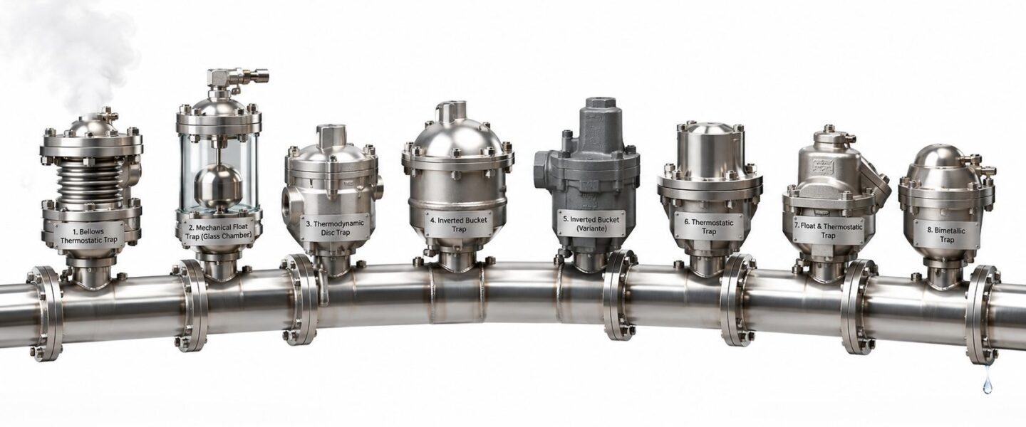
For a visual reference, this industrial steam trap infographic shows the inverted-bucket mechanism and its place among common designs.
2. Thermostatic Bellows and Capsule Steam Trap
A thermostatic trap responds to temperature difference, not directly to condensate level. A sealed bellows or capsule contains a volatile medium that expands as it approaches steam temperature and contracts when exposed to cooler condensate. That movement drives the valve, allowing cooler condensate and air to leave before closing near the steam condition.
This makes the design useful where controlled subcooling is acceptable. Subcooling means condensate remains below the saturation temperature of the steam before discharge. A pharmaceutical sterilizer may need reliable air removal and controlled condensate temperature, while a chemical reactor with a steam jacket may benefit from reducing thermal shock during heating. Dairy pasteurization lines and textile dyeing machines also depend on stable heat control rather than maximum drainage speed alone.
The trade-off is response time. If the element is damaged, incorrectly selected, or exposed to unsuitable condensate chemistry, the trap may remain open, leak steam, or respond too slowly during startup. A failed element can also leave the process with condensate accumulation if the valve doesn't open as the condensate cools.
What technicians should measure
A quarterly condensate-temperature check is more useful than a quick visual glance. Large deviations from the expected operating pattern can indicate bellows damage, seat leakage, incorrect installation, or a changing process load. Excessive lag during commissioning deserves investigation before the trap is accepted into the maintenance route.
- Protect the seat: Use an upstream 100-mesh strainer where dirt could cause leakage.
- Match materials: Stainless steel internals and compatible composite seals suit corrosive condensate better than an unexamined standard build.
- Check orientation: Vertical installation on gravity-return systems supports the intended thermal response.
- Watch startup: A trap that hisses excessively or fails to clear air can delay warm-up and reduce heat-transfer performance.
Thermography can identify abnormal temperature patterns, but insulation and load variation can distort the reading. The technician should compare temperature behavior with process conditions and, where possible, differential pressure across the trap. A stainless-steel cross-section illustrating the bellows mechanism appears in this thermostatic steam trap diagram.
3. Bimetallic Strip Steam Trap
Bimetallic traps use two bonded metals with different expansion rates. Heating bends the combined strip toward the valve seat and closes the trap. Cooling allows the strip to move away and discharge condensate. The mechanism is simple, durable, and suited to services where dirt, temperature cycling, and limited access make intricate moving parts a liability.
A steel mill soaking-pit system may expose the trap to severe thermal cycling. A mining operation may send condensate containing suspended solids and silica through the system. In an oil refinery heat-exchanger network, viscous or contaminated condensate can punish delicate mechanisms, while a power plant may value a durable design across a large reheat-line population.
Bimetallic traps don't provide the same immediate response as a continuous float design. They discharge according to element temperature, so condensate can remain in the equipment until the strip cools enough to open. That can be acceptable on tracing or selected high-temperature duties, but it can reduce heat-transfer performance where the process requires rapid drainage.
Field indicators
Thermography is particularly useful for building a long-term operating baseline. A consistent change in trap-body temperature, especially when paired with process instability, can point to a failed element, blocked outlet, or altered load. Ultrasound can identify irregular discharge or a persistent signal associated with seat leakage, although technicians should distinguish an abnormal pattern from normal intermittent operation.
- Install correctly: A vertical arrangement with the steam inlet at the bottom supports the intended thermal movement.
- Limit solids: An upstream strainer prevents particles from embedding in the seat.
- Choose corrosion resistance: Stainless steel elements are appropriate for outdoor or chemically aggressive locations.
- Plan for fatigue: Repeated heating and cooling can eventually change strip response, so inspection history matters more than a nominal purchase price.
A bimetallic trap on a refinery exchanger should be judged by the consequence of delayed drainage, not just by its resistance to harsh service. If the exchanger's outlet temperature becomes unstable, the maintenance team should check the trap, differential pressure, and return-line back pressure together rather than replacing the element without confirming the root cause.
4. Thermodynamic Disc Steam Trap
A thermodynamic disc trap uses pressure, velocity, and flashing behavior to operate a disc valve. Condensate lifts the disc and exits. As high-velocity steam or flash steam moves beneath the disc, pressure changes force the disc onto its seat. The trap then cycles intermittently.
The compact design has one principal moving part and can tolerate demanding saturated or superheated-steam service. A textile drying frame with intermittent demand may cycle frequently as the load changes. Chemical batch reactors and automotive tumble dryers can also benefit from compact construction where heating and cooling cycles are frequent. Pulp and paper distribution networks may use the design in locations exposed to water hammer.
The trap isn't a universal choice. Heavy dirt, excessive back pressure, trapped air, poor insulation, or insufficient inlet pressure can prevent correct disc seating or cycling. A failed-open disc trap produces a continuous high-frequency acoustic signal and live-steam loss. A stalled or failed-closed unit can leave condensate in a drip leg or process branch.
Commissioning and inspection
The minimum differential pressure must be verified during commissioning. A disc trap that works at one operating condition may stall when the process load or return pressure changes. Strainers should be installed and maintained, and the piping should prevent air pockets from interfering with disc operation.
A thermodynamic trap should be selected for its actual pressure differential and discharge pattern, not because its small body looks suitable for a crowded installation.
Acoustic ultrasound can distinguish normal cycling from a continuously blowing or stalled trap when the technician understands the expected cycle. Visual discharge also helps where the outlet is visible. A lazy, billowy plume may be flash steam from normal condensate discharge, while a sharp, high-velocity plume suggests live-steam blow-through. A steam relief valve maintenance resource can help engineers keep trap discharge risks in the wider pressure-protection context.
The design shown in this disc steam trap cross-section makes the disc-and-seat relationship easier to interpret during inspection.
5. Float-and-Lever Steam Trap
A float-and-lever trap is a mechanical device that responds to condensate level. As condensate rises inside the body, a buoyant float lifts a lever and opens the outlet valve. As the level falls, the valve closes. This creates continuous, modulating discharge, meaning the trap can remove condensate in proportion to the incoming load instead of waiting for an intermittent cycle.
That behavior suits process equipment with changing demand. Large food-processing pasteurizers, chemical reactors, distillation columns, and textile drying complexes can all generate substantial and variable condensate. A pulp and paper steam-recovery network may have many such traps, where a single blocked vent or worn pivot can affect heat recovery and operating stability.
The major advantage is capacity and response to condensate level. The main weaknesses are dirt sensitivity, pivot wear, freezing exposure, and mechanical damage from vibration. A trap that fails open may produce a constant ultrasonic signal and higher downstream temperature. A trap that fails closed may show a cooler body, condensate backup, water hammer, or a process exchanger that floods during high load.
Diagnostics that match the mechanism
Ultrasound is useful for detecting a blocked air vent, failed seat, or continuous bypass. A blocked vent often appears as startup hissing and slow equipment warm-up. Infrared thermography can identify a warm float chamber or abnormal inlet-to-outlet temperature pattern, but the image should be interpreted against load and insulation conditions.
- Protect the chamber: A combination strainer-separator reduces dirt and entrained water entering the float body.
- Check the linkage: With steam isolated, annual manual actuation can reveal stiffness, wear, or a damaged pivot.
- Control vibration: Anchored piping reduces mechanical stress on the lever and connections.
- Review the return: High back pressure can prevent discharge even when the float mechanism is healthy.
The design is often a strong starting point for a modulating heat exchanger because continuous drainage supports stable heat transfer. It still requires correct sizing and differential-pressure verification. Teams building a route-based ultrasound program can use ultrasonic leak detection services to locate failed-open traps and other compressed-fluid losses within the same inspection process.
This float trap cutaway illustrates why float position, linkage condition, and chamber cleanliness affect performance.
6. Orifice Fixed Orifice Steam Trap
A fixed-orifice trap is a calibrated restriction with no moving parts. The opening is sized to pass a predetermined condensate flow while limiting steam loss. It acts more like passive flow metering than a self-adjusting valve, which makes it attractive where maintenance access is poor and the load remains predictable.
District-heating condensate return points may use fixed orifices to avoid maintaining a separate mechanical trap at every building. A steel mill spray header can use calibrated restrictions for known spray demand, while a pharmaceutical autoclave may use an orifice sized to the condensate produced during sterilization. Mining process heaters with low-pressure steam may also benefit from simple flow control.
The limitation is fundamental. An orifice can't modulate to changing loads and can't vent air. If the process load falls, it may pass steam. If the load rises above the design condition, condensate backs up. A blocked orifice can create a cold downstream condition, rising upstream level, poor heat transfer, and water hammer. A partially blocked opening is difficult to identify with visual inspection alone because the device has no cycle to observe.
Design controls
Orifices should be sized conservatively, with operating margin for transients rather than at the absolute maximum flow. Critical services benefit from parallel orifice trains with isolation valves, allowing one path to be serviced while another remains available. Upstream and downstream isolation also makes replacement safer and reduces major disassembly.
Downstream condensate collection tanks should have high-level alarms where backup could affect production. Pressure gauges upstream and downstream reveal whether the available differential pressure matches the design assumption. A temperature comparison can screen for blockage, but differential pressure is often the more direct confirmation.
A fixed orifice works when the load is known and stable. It works poorly as a substitute for a modulating trap on a process exchanger with changing demand.
Material selection matters too. Stainless steel plugs and bodies resist corrosion and reduce the chance that scale will close the passage. Maintenance teams should record the installed orifice size, service duty, pressure conditions, and cleaning history in the CMMS. Without that information, a replacement can restore the symptom briefly while preserving an undersized orifice problem.
7. Combination Composite Steam Trap
Combination traps integrate more than one operating principle in a single assembly. A float-and-thermostatic design, for example, combines level-based condensate discharge with temperature-based air venting. The purpose is to handle two demands that a single mechanism may not meet well, such as high continuous condensate flow and rapid startup air removal.
A large steam-jacketed vessel is a typical example. During startup, air must leave quickly so the jacket can heat evenly. During operation, the trap must remove changing condensate loads without flooding the jacket. Heat-exchanger trains with slugs, intermittent operation, and trapped air can present the same challenge.
The extra capability brings extra maintenance responsibility. A combined trap can fail through the float mechanism, the thermostatic element, a seat, or an internal passage. A temperature-only check may miss a float problem, while an ultrasound reading alone may not explain slow startup. The inspection method needs to separate the functions.
Service strategy
Upstream strainers and separators are essential because debris can impair both mechanisms. During maintenance, technicians should inspect the float, linkage, thermostatic element, seats, and air-vent path rather than replacing only the part associated with the last symptom. The manufacturer's service procedure should define how the assembly is tested after repair.
A useful diagnostic sequence starts with process behavior. If a jacket heats slowly but later drains normally, air removal deserves attention. If the vessel floods during high load, capacity, back pressure, and float movement should be checked. If ultrasound indicates continuous steam flow, the seat or thermostatic element may be leaking.
Combination traps also need clear asset records. The CMMS entry should identify the operating principles inside the assembly, not merely the external body model. This thermographic survey guidance for steam systems, traps, and insulation supports a broader route that compares trap temperatures with nearby piping and insulation conditions.
A process team shouldn't specify a composite trap because it appears more capable. The additional mechanism is justified when the application requires both continuous drainage and dependable air removal.
8. Steam Trap Monitoring and Maintenance Best Practices
A trap route usually breaks down in a familiar way. The inspection gets done, a few bad traps get changed, and six months later the same units fail again because the program recorded a symptom, not the service conditions that caused it. A useful steam-trap program ties failure mode, diagnostic signal, consequence, and work order to each asset so the repair backlog reflects plant risk, not just body count.
Start with the asset record. Each trap should carry location, trap type, service, pressure, installation date, last inspection date, test result, failure mode, and replacement history. Add a few fields that make route data usable in a CMMS: criticality tier, normal operating state, expected failure consequence, upstream strainer condition, and whether back pressure or poor drainage layout is a known issue. That is how repeated failures get traced to design, installation, water quality, or return-system problems instead of being logged as isolated defects.
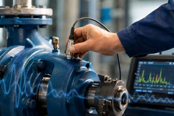
Test methods still matter, but this section is about using those results well. Ultrasound, thermography, and differential pressure each answer a different question, and the technician should enter the finding in a way planners can act on. “Leak suspected” is weak. “Failed open,” “failed closed,” “cycling abnormal,” “high back pressure,” or “cannot confirm due to load condition” drives a better repair decision.
Build route intervals around consequence. High-pressure headers, heat exchangers, turbines, sterilizers, and critical tracing systems need shorter intervals because a blocked trap can flood equipment, trigger water hammer, or interrupt production, while an open trap can waste steam for months before anyone sees it. Partially leaking traps deserve their own code because they often damage energy performance without creating a clear process complaint.
Support equipment needs work orders too. Strainers, separators, check valves, isolation valves, and discharge piping should be inspected on a schedule that matches debris loading and condensate quality. When low-pressure return lines complicate trap discharge, resources like Ring Hot Water pressure help outline how low-pressure hot-tap work affects available differential pressure.
Forge Reliability's ultrasonic steam trap testing service can support a route-based survey that identifies failed-open, failed-closed, and leaking traps. The result should feed the CMMS, criticality ranking, and planned repair backlog, with clear repair codes, target dates, and post-repair verification, rather than sit as a standalone inspection report.
8-Point Steam Trap Comparison
| Trap / Practice | Implementation complexity | Resource requirements | Expected outcomes | Ideal use cases | Key advantages |
|---|---|---|---|---|---|
| Inverted Bucket Steam Trap | Moderate, simple internals but orientation/protection needed | Low–moderate, occasional inspection, upstream strainer, periodic replacement | Reliable cycling, good slug handling, continuous air venting | Variable-load industrial systems, drum dryers, heat exchangers | Fast response, handles condensate slugs and water hammer, low maintenance |
| Thermostatic (Bellows & Capsule) Steam Trap | Low–moderate, compact but orientation and sensitivity matter | Low, periodic testing, strainers, corrosion‑resistant materials for harsh fluids | Precise condensate temperature control and tight subcooling | Sterilizers, chemical reactors, heat‑traced piping, sensitive processes | Accurate temperature control, works at very low ΔP, self‑venting for startup |
| Bimetallic Strip Steam Trap | Low, simple, rugged mechanism | Low, periodic inspection, long replacement cycles possible | Durable long service life, slower response than mechanical traps | Harsh environments, contaminated condensate, outdoor installations | Low cost, tolerant of poor condensate quality, minimal sealed parts |
| Thermodynamic (Disc) Steam Trap | Low, single moving part but needs sufficient ΔP | Low–moderate, noise consideration, regular disc wear checks | Rapid cycling, high capacity, suitable for superheated steam | Cycling loads, superheated steam lines, high‑throughput networks | Simple and robust, tolerant of superheat and water hammer |
| Float-and‑Lever Steam Trap | Moderate, larger chamber and mechanical linkage | Moderate, upstream separator/strainer, mechanical servicing and inspections | Continuous modulating discharge with high capacity | High condensate rate applications (pulp & paper, large exchangers) | High continuous capacity, modulating action, responsive to load changes |
| Orifice (Fixed Orifice) Steam Trap | Very low, no moving parts, simple installation | Minimal routine maintenance but risk of blockage; recommend isolation valves/redundancy | Passive fixed‑rate drainage; effectively zero‑maintenance if not blocked | District heating, low‑maintenance networks, fixed‑rate applications | Absolute simplicity, very low capital cost, no moving parts to fail |
| Combination (Composite) Steam Trap | High, multi‑element internal design requires correct sizing | Higher, more complex servicing, specialized parts, upstream strainers | Broad performance: high capacity plus reliable air/venting at startup | Large steam‑jacketed vessels, heat exchanger trains with variable loads | Merges strengths of multiple types; reduces need for multiple discrete traps |
| Steam Trap Monitoring & Maintenance Best Practices | Moderate, program setup, data standards and scheduling | Moderate, ultrasound, IR thermography, gauges, database, trained staff | Extended trap life, fewer failures, reduced energy loss via condition‑based actions | Any steam plant seeking efficiency, reliability, and lifecycle cost reduction | Early fault detection, data‑driven replacements, energy and downtime savings |
Turning Trap Data Into a Reliability Program
Steam trap selection is an application decision, not a pipe-size decision. The three principal operating groups are mechanical, thermostatic, and thermodynamic. Mechanical traps respond mainly to density differences, thermostatic traps respond to temperature differences, and thermodynamic traps respond to pressure, velocity, and flashing behavior. Those principles determine how each design handles condensate, air, back pressure, dirt, water hammer, freezing, and intermittent or continuous discharge. The U.S. Department of Energy steam trap guide provides the foundational classification and explains why the categories shouldn't be treated as interchangeable.
The selection sequence should start with the service consequence. A modulating process heat exchanger usually needs continuous condensate removal and effective air venting, so a float-and-thermostatic design may be the logical starting point. A steam-main drip leg may need resistance to water hammer and dirt, making an inverted bucket or thermodynamic design more appropriate. A tracing circuit may tolerate subcooling and intermittent discharge, while a sterilizer may place greater emphasis on air removal and temperature control.
The next check is the operating envelope. Engineers should verify inlet pressure at the trap, return-line back pressure, minimum and maximum differential pressure, startup and running condensate load, flash-steam behavior, air load, installation orientation, freeze exposure, and dirt tolerance. A trap that works under normal load can fail during startup or at low differential pressure. An oversized trap can cycle harshly and wear seats, while an undersized trap can flood equipment and create water hammer.
Diagnostics must match the likely failure. Ultrasound is strong for identifying continuous steam leakage and abnormal cycling. Thermography can screen for blocked or failed-open conditions when the temperature pattern is interpreted with process load and insulation. Differential-pressure checks confirm whether the trap has enough driving force to discharge. Visible discharge can separate normal flash steam from live-steam blow-through, but plume appearance should be confirmed with acoustic or temperature evidence.
A practical next step is a population audit by location, trap type, service, criticality, and last inspection date. Prioritize critical process traps for ultrasound and thermography, then rank repairs by steam loss, production consequence, safety exposure, and recurrence. The inspection route should also check strainers, separators, check valves, discharge piping, isolation arrangements, and water-hammer conditions.
Forge Reliability offers predictive maintenance, condition monitoring, thermography, ultrasound, criticality ranking, and reliability consulting for industrial facilities. Plant teams can request a free reliability assessment at Forge Reliability to benchmark trap performance and build a condition-based maintenance plan.
Forge Reliability can survey steam traps with ultrasound and thermography, identify failed-open, failed-closed, and leaking conditions, and connect findings to a practical maintenance strategy. Request a free reliability assessment through Forge Reliability to prioritize critical traps, improve inspection routes, and reduce recurring steam-system failures.