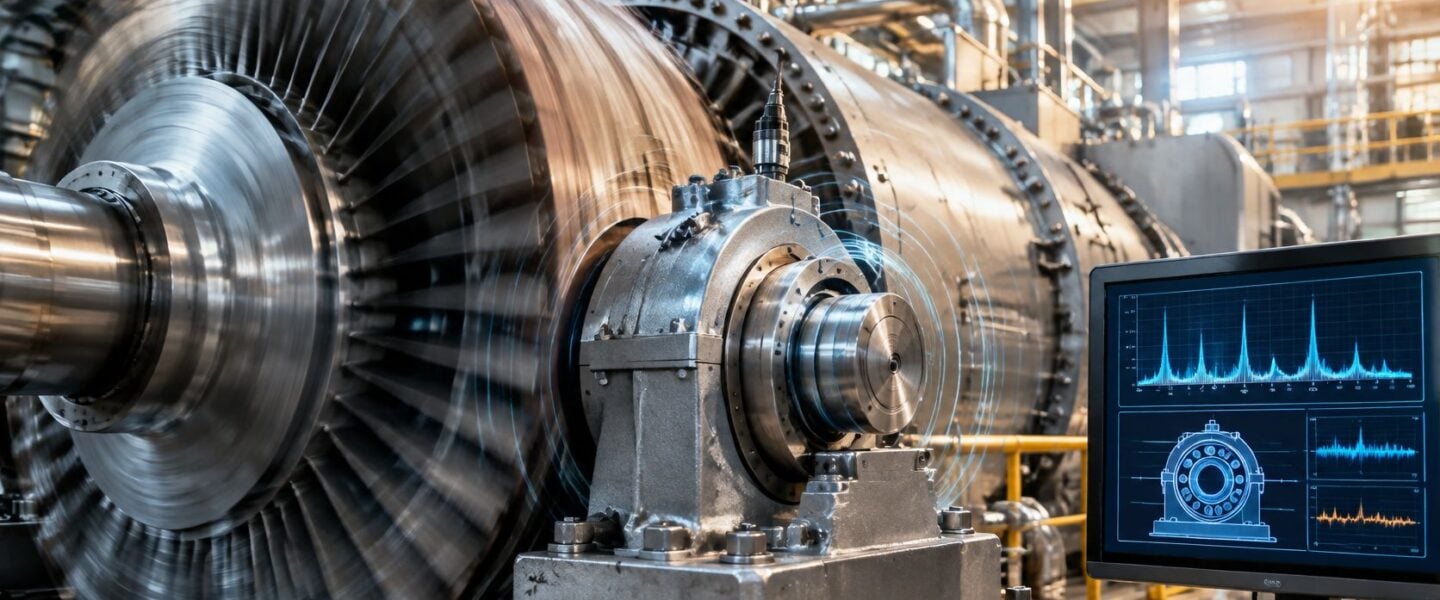
A bearing alarm during a load change rarely tells the story by itself. The overall RMS value, which is a single combined measure of vibration energy, may rise while the spectrum stays clean, or it may sit steady while phase, the angular position of the vibration relative to a once-per-revolution marker, drifts at one pedestal. That's why the same 1x peak, meaning vibration once per shaft revolution, can point to added mass, a bent shaft, looseness, or a thermal problem.
Steam turbine vibration causes separate cleanly when engineers work from measured clues. Compare 1x amplitude and phase, 2x content, subsynchronous peaks that sit below running speed, axial movement, orbit shape, and behaviour through startup. Add operating context, including load, steam admission, bearing-metal temperature, and differential expansion. A sudden vector change points somewhere different from a gradual trend, even when both end at the same alarm level.
Reading the clue before choosing the fix
A 2022 investigation of a supercritical 600 MW steam-turbine generator traced a sudden, high-amplitude event to a blast baffle associated with a coupling bolt that had fallen from the low-pressure rotor coupling. That case matters because balancing wouldn't have fixed a shed component. Neither would a bearing change.
A high overall number is a reason to investigate. It isn't a diagnosis.
The eight faults below are organised by their discriminating clue. Read the spectrum, orbit plot (the trace of shaft centre movement from two probes), and startup record first. Then schedule the outage work that matches the mechanism.
Table of Contents
- Reading the clue before choosing the fix
- 1. Rotor Unbalance in Steam Turbines 1x Running-Speed Vibration
- 2. Shaft Misalignment 1x and 2x Vibration With Axial Components
- 3. Oil Whirl and Oil Whip in Journal Bearings
- 4. Rotor-to-Stator Rub Thermal and Mechanical Contact Damage
- 5. Steam Whirl and Labyrinth Seal Instability
- 6. Blade Resonance and Nozzle Passing Frequency Excitation
- 7. Thermal Bow and Differential Expansion in Steam Turbines
- 8. Mechanical Looseness and Foundation Weakness in Turbine Trains
- How the eight steam turbine vibration causes differ in signature, clue, and failure risk
- Turn Vibration Clues Into Your Next Reliability Decision
1. Rotor Unbalance in Steam Turbines 1x Running-Speed Vibration
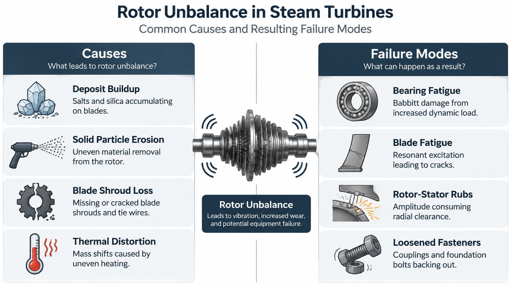
Rotor unbalance occurs when the rotor's mass centre doesn't coincide with its geometric centreline. The rotating centrifugal force lands at running speed, so the spectrum shows a dominant 1x radial peak with little subsynchronous content. Phase at each bearing is usually repeatable while speed and load stay steady.
Deposits drive many slow cases. Salts, silica, and oxides carried over from boiler water build unevenly on blades and disks. Solid particle erosion does the reverse by removing material from one area, and a cracked shroud or lost tie wire removes mass in a step. Because force rises with the square of speed, a modest mass change can look harmless at turning gear and serious at full load.
The discriminating clue
Say a 60 MW condensing turbine in a pulp and paper mill trends upward at 1x over six months. Phase holds steady, 2x stays low, and axial vibration doesn't move. That pattern favours gradual deposit growth over misalignment, so a borescope check for first-stage salt makes more sense than immediate trim weights. The ISO 20816-2:2017 standard page covers land-based steam turbines and turbine-generator sets above 40 MW with fluid-film bearings at 1,500, 1,800, 3,000, or 3,600 r/min, which gives the alarm context for a machine in that class.
- Trend phase with amplitude: Stable phase plus rising 1x supports a mass change, and a sudden phase jump suggests part loss.
- Inspect before balancing: Clean deposits per OEM instructions first, since weights added to a fouled rotor become wrong after cleaning.
- Confirm the measurement: Review how to measure vibrations before trusting a single casing reading.
- Set plant alarms: Use the standard zones as a ceiling and the machine's own baseline as the early warning.
2. Shaft Misalignment 1x and 2x Vibration With Axial Components
Start at the coupling when the spectrum shows more than a clean 1x peak. Misalignment means the centrelines of two coupled shafts, or of a shaft and its bearing supports, don't match. That mismatch preloads the coupling and bearings, and it commonly produces strong 2x radial vibration plus an axial component that unbalance rarely explains.
Thermal growth causes most turbine-train cases. A casing set correctly when cold can rise or shift once steam heats the supports, and piping strain can pull a flange after modification work. Foundation settlement and worn coupling hubs add offset over time, while the forces repeat every revolution even though the shaft may be well balanced.
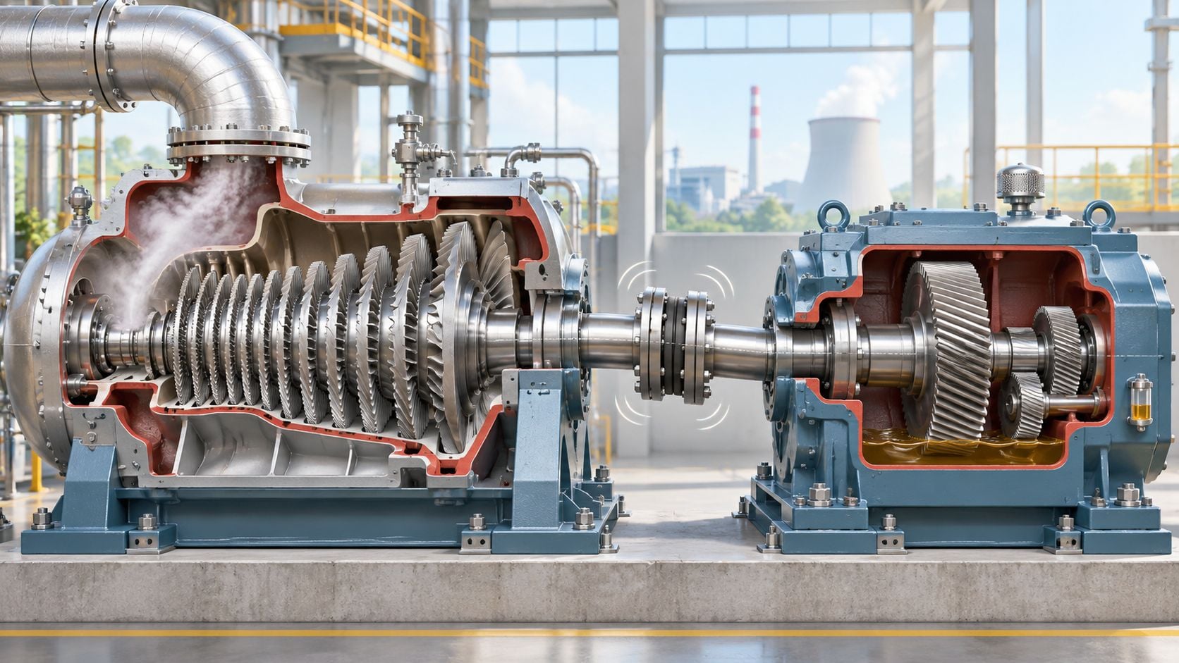
In a worked example, a 25 MW turbine driving a boiler feed pump through a gearbox shows 2x radial amplitude twice the 1x level. Axial vibration climbs at the coupling-end bearing and the coupling runs hot. A hot alignment check finds the casing 0.6 mm high relative to the gearbox after a steam valve change added piping load. Lifting the gearbox supports and fixing the pipe support removes the force, whereas balancing would only mask it.
Checks that separate it from unbalance
The Fire Protection Research Foundation guidance lists shaft misalignment among the primary causal categories alongside bowed rotors, incorrect radial or axial clearances, and coupling deterioration. That separation matters during triage.
- Use the 2x-to-1x ratio: A rising ratio with axial content points to the coupling before the rotor mass.
- Verify hot, not only cold: Compare measured growth with the OEM thermal model after piping or foundation work.
- Separate load paths: Review radial vs axial load so thrust movement isn't confused with coupling-driven axial vibration.
- Record tolerances in the CMMS: Future crews need the same targets, not a memory of the last outage.
3. Oil Whirl and Oil Whip in Journal Bearings
A peak below running speed changes the priority. Oil whirl is a self-excited instability in a fluid-film journal bearing, where the oil wedge drives the journal around inside the clearance at roughly 0.42 to 0.48 times running speed. It isn't forced by rotor mass, so it can persist after a good balance.
Oil whip is the dangerous step. The whirl frequency locks onto the rotor's first critical speed, which is the speed where the rotor's natural vibration mode is most easily excited, and it stays there as operating speed rises. Amplitude can grow fast in a lightly loaded bearing, an over-clearance bearing, or a bearing fed with oil that's too cold and viscous.
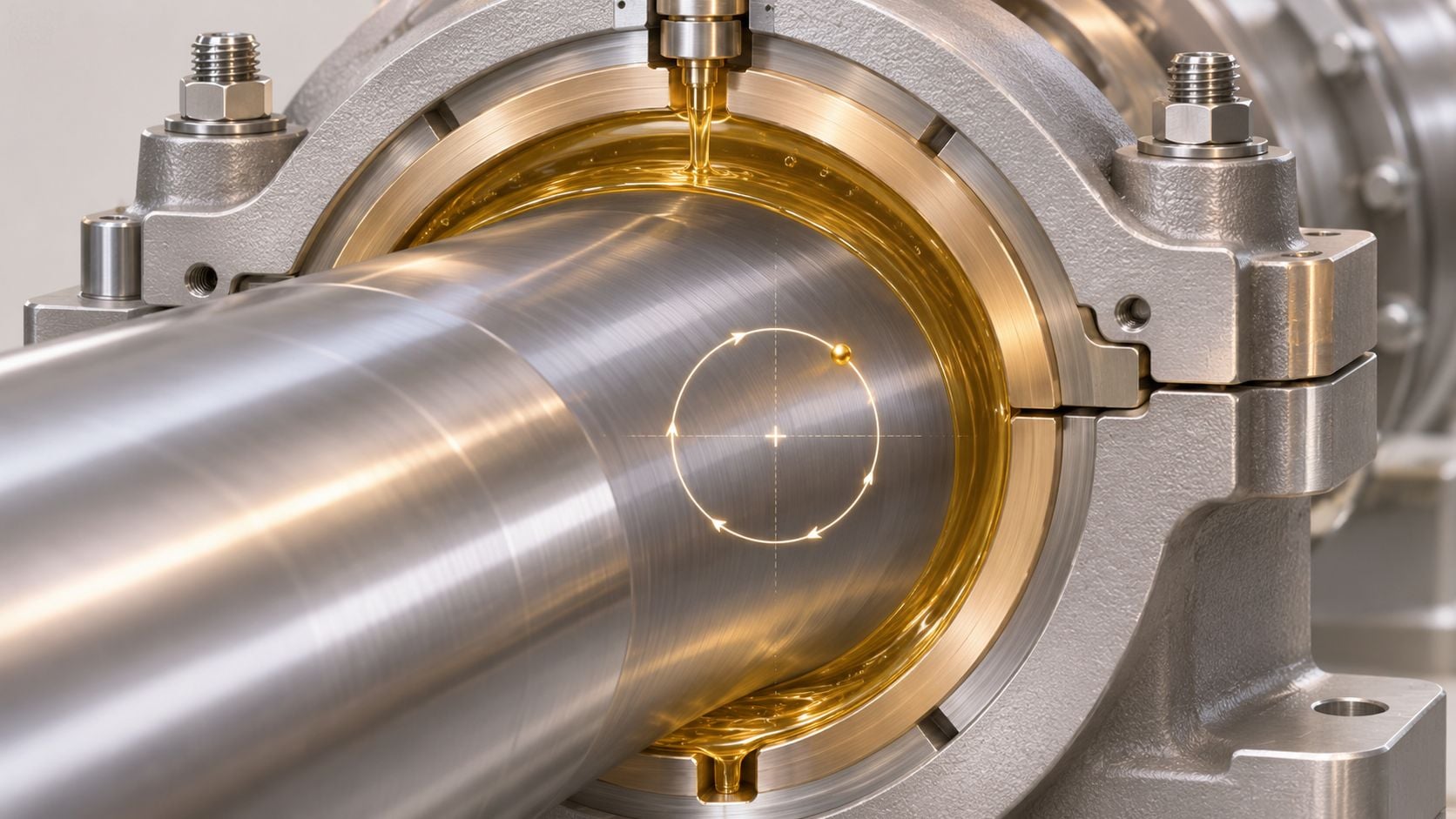
Consider a 40 MW turbine-generator that returns from a bearing overhaul with a new 0.45x peak. The peak grows when load drops and the orbit becomes large and forward-whirling. Measurement shows the replacement bearing was set with clearance above the OEM specification, so restoring clearance and correcting oil supply temperature removes the instability. An investigation published in the Journal of Physics Conference Series diagnosed abnormal vibration as oil whirl caused by insufficient bearing stability, which matches that load-sensitive pattern.
- Trend subsynchronous content separately: Overall amplitude can hide a growing sub-1x peak until it's large.
- Check the bearing build: Verify clearance, preload, oil temperature, and viscosity against OEM values after every overhaul.
- Don't balance an instability: Reducing 1x won't remove a self-excited oil-film mechanism, a point that also shapes decisions about failure of bearings.
- Consider the bearing type: Tilting-pad designs resist whirl better on machines with a repeat history.
4. Rotor-to-Stator Rub Thermal and Mechanical Contact Damage
Noise, heat marks, and a spectrum that won't sit still point toward contact. A rub occurs when a rotating part touches a stationary part, usually a labyrinth seal, packing, or casing bore. Clearance disappears because of thermal bow, casing distortion, bearing misalignment, or vibration that's already too high for the seal gap.
The clue is rarely one tidy peak. Rubs produce broadband energy, subharmonics, changing 1x phase, and an orbit that flattens or truncates where contact occurs. Friction heats one side of the shaft, bends it further, and tightens the contact, so a light seal kiss can become a shaft bow during one bad start.
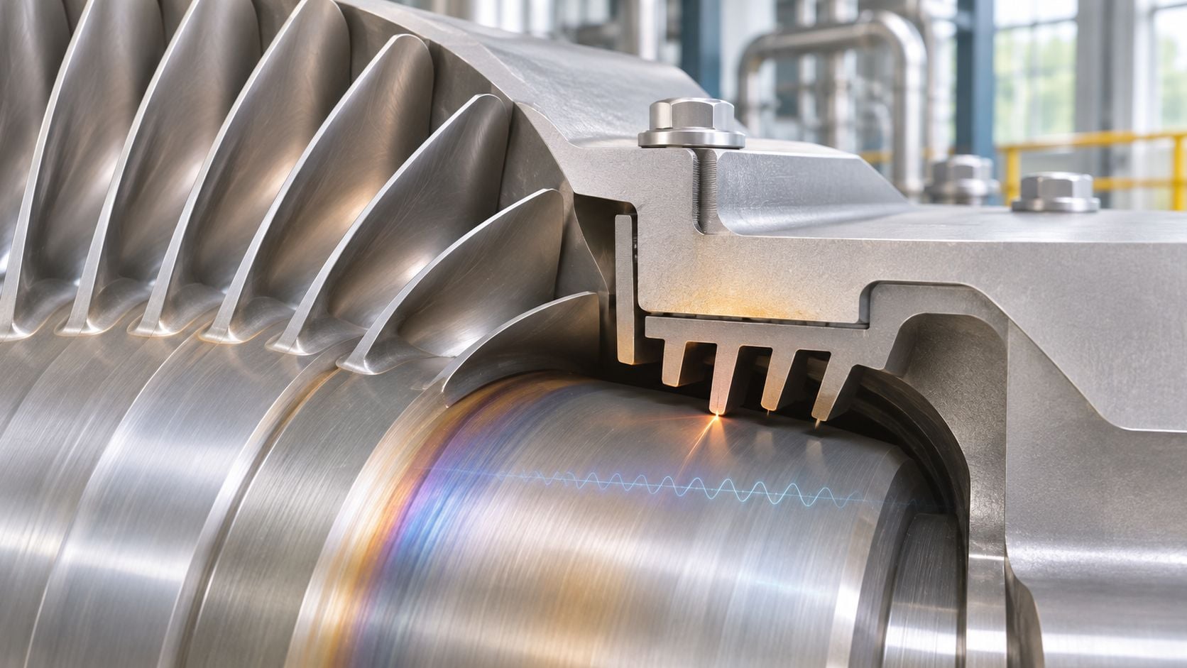
Say a 90 MW refinery turbine alarms during a fast startup after a short outage. The shaft centreline moves toward the high-pressure packing, broadband content rises, and operators hear intermittent contact. Inspection finds scored packing, and the corrective action is a slower ramp with longer holds for differential expansion, plus measured seal clearance correction at the next opening.
The intermittent rub that route data misses
A published case analysis in the Journal of Physics Conference Series identifies oil-seal carbon deposition as a contributor to intermittent vibration, where casing heat near the steam seal cokes the oil seal and ultimately permits rotor-to-stator rubbing. A steady-state route reading won't catch that sequence.
- Correlate with startup logs: Match vibration and shaft position to metal temperatures, ramp rate, and time since admission.
- Trend shaft centreline: Position drift often warns before amplitude crosses a limit.
- Inspect seal condition: Look for coking, contamination, and clearance loss rather than ordering a balance.
Practical rule: If vibration appears only during warm-up or after hours at temperature, capture the transient. Steady data taken later can look normal.
5. Steam Whirl and Labyrinth Seal Instability
Balance is good. Alignment is good. A subsynchronous peak still grows when the machine loads up. That load dependence is the clue for steam whirl, a self-excited instability driven by cross-coupled aerodynamic forces in labyrinth seals and gland packing.
Cross-coupled means steam pressure in the seal pushes the rotor sideways in a direction that adds energy to its whirling motion. The resulting component often sits near 0.5x running speed, appears above a load or inlet-pressure threshold, and may vanish when operators unload. Oil whirl, by contrast, tracks bearing conditions and speed more closely than steam admission.
Separating steam force from oil-film force
Take a 70 MW steel mill turbine as the scenario. At moderate load the spectrum is clean, but at high inlet pressure a subsynchronous peak near 0.5x rises at the high-pressure end. Orbit growth follows load within minutes, while oil temperature and bearing-metal temperature stay steady. That pattern sends the team to the high-pressure labyrinth seal, where worn teeth have enlarged the clearance and increased swirl.
Replacing the seal with a honeycomb or abradable design reduces the destabilising cross-coupling. Forge Reliability supports steam turbines in metals and steel where common failures involve degradation of the blades, journal bearings, and seals, so seal condition belongs in the same review as bearing condition.
- Plot against process variables: Chart subsynchronous amplitude against load, inlet pressure, and valve position, not speed alone.
- Measure seal clearances: Compare every labyrinth stage with design values during outages.
- Test by unloading: A peak that falls promptly with steam flow supports a steam-force mechanism.
- Involve the OEM early: Seal geometry changes affect both efficiency and rotordynamic stability.
6. Blade Resonance and Nozzle Passing Frequency Excitation
A casing spectrum won't always show the blade problem clearly. Blade resonance occurs when a blade row's natural frequency, the frequency at which it vibrates most readily, coincides with a steam-path excitation. The strongest regular excitation is nozzle passing frequency, calculated as the number of stationary nozzles multiplied by running speed divided by 60, because each rotating blade crosses nozzle wakes every revolution.
Resonance shows on a Campbell diagram, which plots blade natural frequencies against speed and marks where excitation lines cross them. Operating at a crossing multiplies blade stress without necessarily producing a large shaft 1x response. That's why blade fatigue can advance while bearing trends look acceptable, especially after changes to partial admission, valve sequencing, or a blade repair that shifts frequency.
A 2024 Springer study modelled steam-flow excitation at 2,100 Hz in the last-stage blades of a steam turbine with 42 guide blades, while rotor vibration in sliding bearings produced a 50 Hz kinematic excitation. The separation between those frequencies shows why shaft probes alone can't clear a blade row.
Worked scenario
Say a 35 MW food processing turbine develops a last-stage crack after switching to partial-admission operation at a common speed. Shaft vibration stays modest, but the new admission pattern raises excitation at a blade mode. The response is to avoid that speed band, inspect by NDT, and reassess damping rather than rebalance the rotor.
- Keep the Campbell diagram current: Update it after blade, nozzle, or operating-mode changes.
- Use modal thinking: Review what is modal analysis when a repair changes blade mass or stiffness.
- Inspect on evidence: Target dye penetrant or ultrasonic checks at rows operating near a crossing.
7. Thermal Bow and Differential Expansion in Steam Turbines
High 1x at startup that decays with time at speed isn't ordinary unbalance. Thermal bow occurs when uneven heating or cooling bends the rotor, shifting its effective mass distribution. Differential expansion is the related casing problem, where rotor and casing grow at different rates and consume axial or radial clearance during starts, trips, and large load swings.
The key symptom of rotor thermal distortion in steam turbines is high 1x vibration during transient operations with slow decay. Phase may migrate as the bow straightens, and slow-roll runout, meaning shaft eccentricity measured at turning-gear speed, is high before steam admission. A true mass unbalance doesn't normally create that starting runout or improve because the rotor soaks at temperature.
The Morton effect trap
A thermal mechanism described in Thermal Science is the Morton effect, where viscous shearing in the oil film creates a circumferentially uneven temperature rise in the bearing journal, producing thermal expansion and bending of the rotor. The changed orbit increases heating, and the heating increases the bow. Vibration that rises after prolonged operation, with phase drift tied to oil and bearing temperatures, fits that loop better than static unbalance.
Say a 120 MW combined cycle steam turbine trips hot and restarts with high 1x and high eccentricity. Operators find turning gear wasn't maintained through cooldown, so the rotor sagged and bowed. Extending the soak and correcting turning-gear practice removes the start problem without balance weights.
- Record runout every start: Compare cold, hot-restart, and post-trip values at the same probe location.
- Protect cooldown: Confirm turning gear operation until the OEM releases the rotor.
- Correlate metal temperatures: Pair casing and bearing thermocouples with vibration, and use thermography inspections where casing hot spots are suspected.
8. Mechanical Looseness and Foundation Weakness in Turbine Trains
Multiple harmonics at one pedestal should send engineers to the soleplate before the rotor. Mechanical looseness means bolts, bearing caps, pedestals, casing supports, or grout have lost rigidity, so normal 1x force produces non-linear motion. The spectrum shows 1x plus 2x, 3x, and higher harmonics, sometimes with half-order content, and readings may change with load direction or bolt condition.
Soft foot is the common setup fault, where one machine foot doesn't sit flat and distorts the casing when tightened. Cracked or debonded grout does similar damage at the foundation. Both lower support stiffness, shift alignment, and make other faults, including unbalance and misalignment, look larger at the affected bearing than elsewhere on the train.
Consider a 30 MW pulp and paper turbine-generator with a harmonic series at one pedestal only. Phase is unstable, vertical amplitude exceeds horizontal by a wide margin, and the spectrum changes after operators reload the machine. Inspection finds cracked grout and loose anchor bolts, so regrouting, correcting soft foot, and torquing to specification collapse the harmonics. Realigning after the repair is mandatory because the support geometry has changed.
Setting limits for smaller turbines
The ISO 20816-3:2022 project summary covers industrial machinery above 15 kW operating from 120 to 30,000 r/min, including steam turbines and generators rated at or below 40 MW. That scope fits many process turbines where route data and online probes need the same measurement locations.
- Check torque and soft foot: Complete both during every major outage, not only after an alarm.
- Inspect grout properly: Sound the pad for voids and look for cracks or oil-soaked delamination.
- Trend harmonic content: A rising harmonic series at one bearing is a looseness flag even when 1x is stable.
How the eight steam turbine vibration causes differ in signature, clue, and failure risk
| Item | Dominant Frequency Signature | Key Diagnostic Clue | Typical Failure Mode |
|---|---|---|---|
| Rotor Unbalance in Steam Turbines: 1x Running-Speed Vibration | Dominant 1x running-speed peak | Stable phase angle; radial vibration often strongest near the imbalance | Bearing fatigue, blade fatigue, rotor-stator rubs, or loosened fasteners |
| Shaft Misalignment: 1x and 2x Vibration with Axial Components | Elevated 1x and 2x running-speed components | Strong axial vibration; heat near the coupling | Coupling fatigue, thrust-bearing overload, or shaft fatigue |
| Oil Whirl and Oil Whip in Journal Bearings | Subsynchronous peak, typically 0.42x–0.48x; oil whip locks to the first critical speed | Large circular shaft orbit, often at light load or after bearing changes | Babbitt failure, rotor rub, or journal damage |
| Rotor-to-Stator Rub: Thermal and Mechanical Contact Damage | Broadband or subharmonic vibration | Shaft centerline shifts toward the casing; vibration changes with thermal transients | Seal damage, blade-tip wear, shaft bow, or casing cracks |
| Steam Whirl and Labyrinth Seal Instability | Subsynchronous vibration near 0.5x running speed | Vibration increases with steam pressure and load; often associated with seal wear | Rotor instability, seal rub damage, or bearing overload |
| Blade Resonance and Nozzle Passing Frequency Excitation | Nozzle passing frequency and harmonics; sharp high-frequency peaks or sidebands | Resonance at specific speeds identified on a Campbell diagram | Blade fatigue cracks, blade loss, or shroud failure |
| Thermal Bow and Differential Expansion in Steam Turbines | Elevated 1x vibration that varies with temperature | Shaft runout and vibration change during startup or shutdown | Rubs, shaft damage, bearing overload, or casing distortion |
| Mechanical Looseness and Foundation Weakness in Turbine Trains | Multiple running-speed harmonics, including 1x, 2x, and 3x | Vibration changes with bolt torque, grout condition, or support movement | Foundation cracks, bolt fatigue, misalignment, or bearing damage |
Turn Vibration Clues Into Your Next Reliability Decision
A vibration alarm is useful only when it points to a repeatable machine condition. Check sensor mounting first. Then compare shaft-relative readings from proximity probes with casing vibration, separating running-speed components from harmonics and subsynchronous content. Phase, orbit shape, shaft centerline, and behavior through critical speeds help distinguish faults that can share a similar overall reading.
That distinction changes the repair decision. Balancing a rotor will not correct fouling, and replacing a journal bearing will not fix excessive seal clearance. A loose pedestal can also raise casing vibration without showing the same level of shaft distress. Base each action on a clue another engineer can reproduce from the data.
Limits need a baseline
Vibration limits depend on machine size, speed, bearing arrangement, probe location, and operating state. Casing readings can be amplified by the structure, so they do not always reflect shaft distress. ISO 20816-3:2022 covers in-situ broad-band evaluation for industrial machines from 120 to 30,000 r/min, including steam turbines and generators up to 40 MW. It addresses changes from steady values as well as vibration levels themselves.
Apply that principle to the plant alarm philosophy. A turbine can remain below a general limit while phase drift, a growing orbit, or a changing startup Bode plot signals a developing problem. Rate-of-change alarms and event-triggered transient capture can reveal behavior that a monthly overall reading misses, especially when symptoms occur during warm-up and recede at steady load.
- Trend the vectors: Store 1x and 2x amplitude and phase at each bearing, not overall amplitude alone.
- Tie spectra to operations: Record load, speed, steam pressures, valve position, oil temperature, and bearing-metal temperature with each capture.
- Capture starts and trips: Save runout, Bode, polar, and centerline data from starts associated with rough operation.
- Inspect the support path: Include seals, bearings, coupling, pedestals, grout, and piping strain when defining outage scope.
Give priority to the fault that explains the measured clues. Treat other causes as hypotheses until the data supports them.
Forge Reliability's steam turbine vibration analysis monitors shaft vibration, blade-pass frequencies, and bearing stability using proximity probes and casing accelerometers. Its steam turbine condition assessment includes performance evaluation, trip system testing per API 612, and blade inspection. These checks help connect vibration findings to outage scope, parts, and protection-system checks. A free reliability assessment can review spectra, transient records, bearing history, and alarm logic to help prioritize balancing, alignment, seal, bearing, instrumentation, or foundation work.
Request a free reliability assessment from Forge Reliability to review steam turbine spectra, orbits, startup data, and alarm settings against the fault clues in this guide. Bring a rough-start record and the latest bearing trend to help define an inspection and monitoring plan for the next operating cycle.