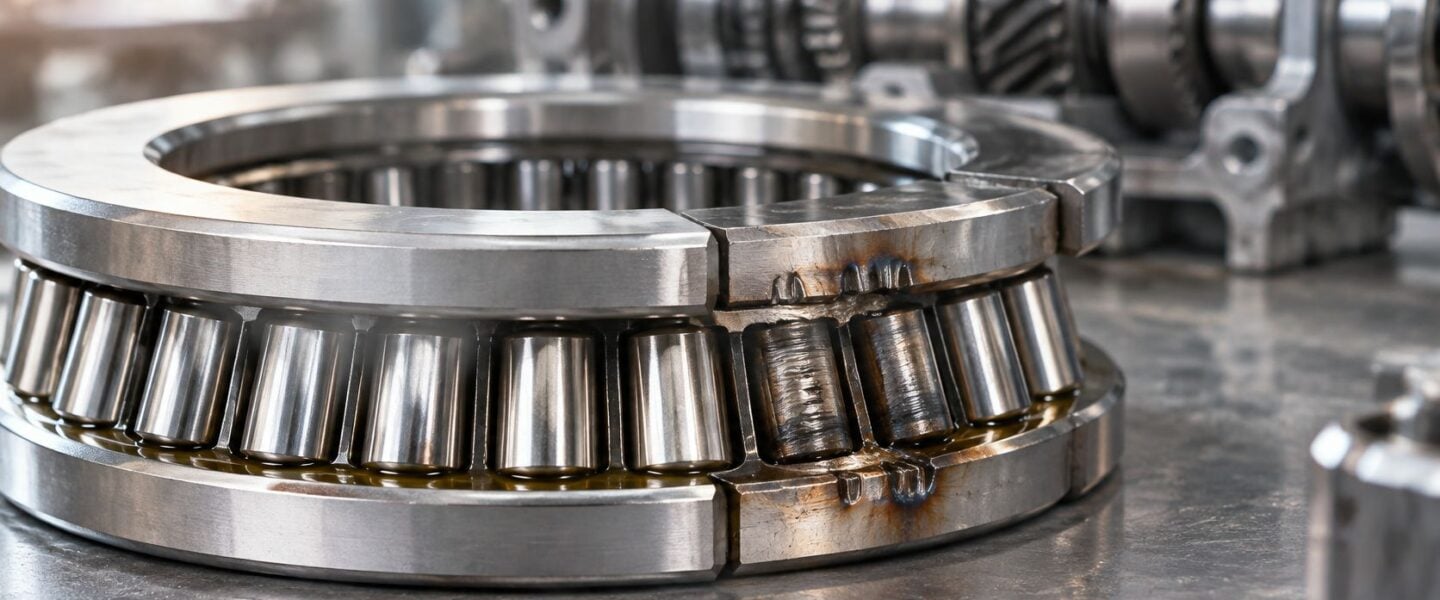
“Keep the load below the catalog rating” is incomplete advice for a thrust needle bearing. A maintenance team can follow that rule and still replace damaged rollers repeatedly because the washer is soft, the housing face isn't flat, or lubricant never reaches the contact.
Reliable selection starts with a different question: What conditions make the calculated bearing life achievable? For compact thrust assemblies, the answer often rests as much on the raceway beneath the rollers as on the bearing designation.
Table of Contents
- Ratings That Set Thrust Needle Bearing Life
- How a Thin Roller Stack Carries Axial Load
- Brinelling Wear and Starvation You Can See
- Oil and Grease Choices for Axial Contact
- Receiving Inspection and Installation Checks
- Watching an Agitator Gearbox Thrust Face
- Request a Free Reliability Assessment
Ratings That Set Thrust Needle Bearing Life
A catalog page hands you three numbers, and each answers a different question. The SKF AXK 1730 product specification lists a basic dynamic load rating of 11 kN (2,473 lbf), a basic static load rating of 40.5 kN (9,105 lbf), and a reference speed of 4,500 r/min. The dynamic rating is a life basis: it defines the constant load at which the bearing reaches a basic rating life of 1 million revolutions under specified conditions, and it sets no ceiling on permissible operating load.
That distinction changes the selection review. Dynamic rating, designated C, feeds fatigue-life calculations. Static rating, designated C₀, measures resistance to permanent contact deformation. Reference speed marks a thermal check point; approval to run at that speed still depends on actual lubrication and load conditions. Treating C as a load limit oversizes the bearing while leaving the durability question unanswered.
Read the ratings as separate checks
The AXK 1730 figures below come from the linked SKF specification. The light and heavy catalog bands reflect McMaster-Carr product categories and their stated temperature options.
Thrust needle bearing ratings to check before selection
| Reference | Dynamic rating | Static rating | Speed or temperature | Decision it supports |
|---|---|---|---|---|
| SKF AXK 1730 roller-and-cage assembly | 11 kN (2,473 lbf) | 40.5 kN (9,105 lbf) | 4,500 r/min reference speed | Life basis of 1 million revolutions, with no implied load ceiling |
| Light catalog range | Less than 2,000 lb | Obtain the selected part's static rating | Maximum-temperature option 230°F | Confirm shock and standstill load against the static rating |
| Heavy catalog range | 30,000 lb or greater | Obtain the selected part's static rating | Maximum-temperature option 240°F | Verify washer hardness, finish, and oil path before use |
| No separate washers | Same assembly rating only if faces qualify | Same assembly rating only if faces qualify | Limited by face hardness and finish | Raceway condition becomes the maintenance variable |
The catalog bands describe separate product categories with different temperature options, so treat them as category guidance. The selected part's own sheet governs both its load rating and its temperature limit.
Calculate life before approving duty
First establish equivalent axial load P, the constant load that represents the fatigue effect of the duty cycle. For a variable duty, weight each load level by its time at load and shaft speed; a simple arithmetic average hides the fatigue contribution of the heaviest segments.
For a clearly hypothetical AXK 1730 duty with P = 5.5 kN, the basic roller-bearing life calculation gives:
L₁₀ = (C/P)^(10/3) = (11/5.5)^(10/3), approximately 10 million revolutions.
Here, L₁₀ means basic rating life, conventionally associated with survival of most bearings in a comparable population under the calculation assumptions. It offers no guaranteed replacement interval, and contaminated oil or unsuitable raceways fall outside its assumptions.
Check maximum parked and shock loads separately against C₀. Presses, pumps, and gearboxes can pick up permanent indentations long before rolling-contact fatigue limits life, so the work order should state the required static safety margin.
Selection rule: Size for fatigue life, check peak loads for permanent deformation, and refuse to credit catalog capacity to an unqualified raceway.
A load below C still fails to protect against inadequate hardness, shaft deflection, misalignment, poor finish, or missing lubrication. The roller set has no way to compensate for a soft or rough track, which makes washer or integral-face hardness the maintenance variable that decides whether the calculated 1-million-revolution basis is real. An unsuitable integral face needs correction or a qualified washer; no derating factor substitutes for a raceway that meets hardness and finish requirements.
How a Thin Roller Stack Carries Axial Load
Consider the output shaft of a compact gearbox. Gear forces push along the shaft, but the designer has little room between the shaft shoulder and housing cover. A thrust needle bearing accommodates that push through a cage of long, slender rollers positioned between opposing raceways.
Axial load acts parallel to the shaft. The cage spaces and guides the rollers; it isn't the main load-carrying member. The raceways are the hardened tracks against which the rollers carry force.
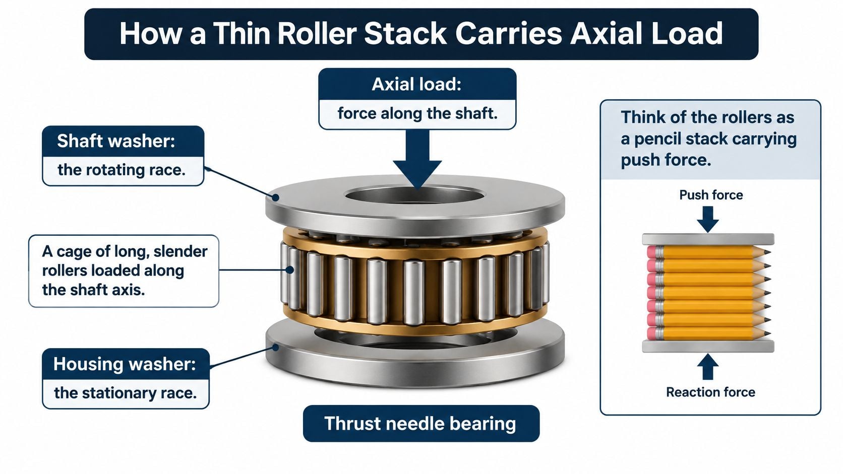
Think of pencils beneath a plate
A row of pencils beneath a heavy plate illustrates the geometry. Each pencil supports the plate along a narrow strip, while the stack remains only as tall as the pencil diameter. A marble beneath the same plate requires more height and concentrates contact into a smaller region.
Bearing contacts deform under load, so actual contact isn't an ideal mathematical line. Nevertheless, line contact explains both the compact load capacity and the sensitivity to uneven support.
A dished washer, tilted shaft, or locally soft face prevents the rollers from sharing load evenly. Edge loading occurs when force concentrates toward the roller ends instead of spreading across their useful length. A stiff assembly can therefore be unforgiving of a flexible mounting arrangement.
Specify the whole thrust interface
A usable work order identifies more than the cage designation:
- Roller-and-cage assembly: The correct bearing designation and orientation.
- Shaft washer: The raceway associated with the rotating shaft.
- Housing washer: The opposing raceway supported by the stationary housing.
- Lubricant film: The separating layer that must reach the actual roller path.
Where qualified shaft and housing faces provide the raceways, separate washers may be omitted. That saves axial space and components, but transfers bearing-surface responsibilities to expensive machine parts. A damaged replaceable washer is usually easier to address than a damaged shaft shoulder.
A nearby radial needle bearing isn't a substitute. Radial load acts perpendicular to the shaft, and the load path must match the bearing arrangement; the distinction between radial and axial load belongs in the drawing review.
The equipment drawing should explicitly identify the build as washer-present or integral-raceway. Otherwise, stores personnel may supply the correct cage while maintenance overlooks the surface that determines whether the assembly can carry its duty.
Brinelling Wear and Starvation You Can See
True brinelling and false brinelling can leave similarly spaced marks, but their corrective actions differ. True brinelling is permanent plastic indentation caused by excessive contact loading. False brinelling is fretting damage, meaning small-amplitude rubbing at loaded contacts, commonly associated with vibration while the shaft is idle.
Photograph each washer before cleaning. Record orientation, loaded face, roller spacing, and the location of visible debris. Scrubbing away reddish residue or smearing a damaged track can remove the evidence needed to distinguish an overload from idle vibration.
Match the signature to the driver
Thrust needle bearing failure signatures and first actions
| Mode | What you see | Likely driver | First action |
|---|---|---|---|
| True brinelling | Pitch-spaced dents without heat tint | Shock or standstill load near the static rating | Recalculate parked and shock load; replace bearing and washers |
| False brinelling | Fretting at roller pitch after idle time | External vibration with no separating film | Isolate vibration and maintain suitable protection during layup |
| Abrasive wear | Polished or scored path and metal in the oil | Contamination or poor sealing | Fix seals, flush the housing, and replace if endplay grew |
| Lubrication starvation | Heat tint, smeared roller ends, discolored cage | Dry grease, oil missing the thrust face, or excessive speed-related heat | Restore the film and confirm oil path and reference-speed suitability |
| Edge loading | Spalling only at roller ends | Misalignment or a soft, dished washer | Correct alignment and raceway hardness before refit |
Roller pitch is the spacing between successive rollers. Matching that spacing supports a contact-related diagnosis, but spacing alone doesn't establish the mechanism.
True brinelling typically produces defined depressions with little heat discoloration. False brinelling may show reddish or dark fretting debris without a recorded overload event. A standby pump exposed to vibration from an adjacent operating machine illustrates why a stationary shaft isn't necessarily a protected shaft.
Abrasive wear occurs when hard particles pass through the contact and remove material. A polished path alone isn't conclusive, but scoring, metallic debris, and increasing axial looseness strengthen the diagnosis.
Use operating evidence before naming the failure
Lubrication starvation means insufficient lubricant reaches the contact to maintain an effective separating film. Straw or blue discoloration, smeared roller ends, and cage discoloration suggest excessive heat, although color alone shouldn't establish operating temperature.
Spalling is flaking or breakout of raceway material. When damage begins only at roller ends, maintenance should investigate washer support, shaft tilt, and local hardness rather than treating every flake as ordinary fatigue.
Useful field evidence includes:
- Axial vibration change: A sustained increase from the established operating baseline.
- Bearing-cap heating: A local rise that can't be explained by sump temperature alone.
- Lubricant debris: New metallic particles or a changing wear pattern.
- End float growth: Greater axial shaft movement than the recorded cold baseline.
These observations should be evaluated together. The broader bearing failure diagnostic process helps separate the visible damage from the condition that initiated it.
Replacing a damaged cage without identifying the washer's failure mechanism preserves the cause of the next outage.
The first action should address the driver before stores orders another identical assembly. A harder washer won't isolate external vibration, and cleaner oil won't correct a tilted shaft.
Oil and Grease Choices for Axial Contact
Lubricant can sit in the sump and still miss the thrust face. Axial roller contact needs a film across a flat raceway, and a shoulder or housing recess can block the feed path even when the sight glass shows a healthy oil level.
McMaster-Carr's thrust needle bearing catalog lists dynamic thrust-load-capacity categories from less than 2,000 lb to 30,000 lb or greater, with maximum-temperature options including 230°F and 240°F. A hypothetical 250°F sump would already exceed those listed temperature options before local contact heating is considered.
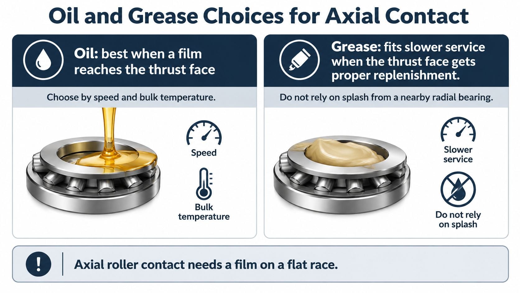
Select the delivery method with the lubricant
The speed and temperature ceilings for a given size carry over from its rating data in the ratings section. What the lubricant decision changes is how the contact stays fed.
Grease versus oil for thrust needle bearings
| Factor | Grease | Oil |
|---|---|---|
| Speed | Lower speed, well below the bearing's reference speed | Near or above reference speed requires thermal and manufacturer review |
| Temperature | Stays within the catalog maximum for the selected rating | Cooling controls bulk temperature; the bearing's listed maximum still applies |
| Thrust face wetted | Only if grease remains in and replenishes the roller path | Required through a drilled feed, flinger, or housing dam |
| Relubrication | Set by operating hours and contamination | Managed through sump level, delivery condition, and oil analysis |
| Selection rule | Sealed, slow, and within temperature limit | Fast, hot, above the oil level, or shock-loaded, with verified delivery |
Grease suits a protected pocket when it stays available to the rollers. Repeatedly filling the cavity can increase churning, heat, and roller sliding without solving poor replenishment. Quantity and interval should come from operating duty and inspection evidence, not an automatic calendar shot.
Oil is generally preferable when heat removal and controlled delivery matter. A flinger throws oil toward the contact; a housing dam retains oil near the washer. Neither feature earns credit until its operation has been confirmed at the actual rotation direction, speed, and sump level.
A bearing below its dynamic rating can still fail when the lubricant film is missing.
The dynamic rating describes a life basis at one million revolutions, not a wall the load cannot cross. That life only holds while a film separates the rollers from the washers, so delivery verification belongs in the specification alongside the lubricant name.
Select viscosity, the lubricant's resistance to flow, for the operating temperature at the thrust location. Cutting viscosity to reduce churning requires a fresh film and life assessment, not merely confirmation that the sump runs cooler.
Seal selection governs lubricant retention and contamination exclusion at the same time. Sixrace's indicazioni sui paraoli SKF per moto shows how seal choice follows shaft speed, fluid compatibility, and the surrounding contamination environment; an industrial gearbox seal needs the same matching against its own oil, speed, and operating surroundings.
The maintenance specification should name grease or oil, the approved temperature ceiling, and the delivery feature on a sketch. A repeatable oil sampling and analysis program then tracks wear metals and oil condition rather than relying on appearance alone.
Receiving Inspection and Installation Checks
A cage with the right outside diameter can still fail to fit the washer it is paired with. Matching boundary dimensions doesn't establish washer compatibility, assembled height, or the contact pattern under load.
ISO 3031:2021 specifies boundary dimensions and tolerances for thrust needle roller-and-cage assemblies and recommends washer dimensions and tolerances, giving the inspector a controlled basis for acceptance rather than reliance on informal catalog sketches. A certificate written against a general thrust-bearing standard doesn't demonstrate compliance with these dedicated requirements. The standard also doesn't eliminate the need to verify the machine drawing, raceway requirements, and supplier-specific application limits.
That verification matters because the dynamic rating assumes a hardened, correctly supported raceway. The rating is a one-million-revolution life basis, not a load ceiling, and a soft or unfinished face spends that life before the rollers do.
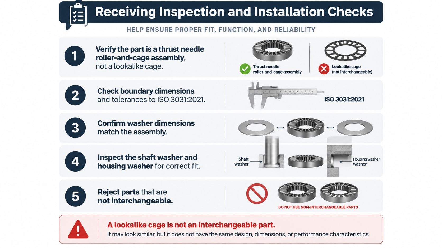
Receive the stack, not just the cage
Before a brand substitution, the planner should verify designation, washer thickness, shaft and housing fits, raceway hardness, axial clearance, and tolerance class. A tolerance class defines the permitted dimensional variation on each part; the tolerance stack is the combined effect of those variations across the assembled cage, washers, and housing. Two components can each be in tolerance and still produce an assembly with too little axial clearance or a washer that sits proud of its seat.
For a critical gearbox, receiving inspection should compare measured dimensions with the applicable standard and drawing. Micrometers suit washer-thickness checks, while the inspection method for flatness and hardness must suit the component geometry and specified acceptance requirements.
Supplier certificates should remain attached to the asset's parts record. A certificate for the cage alone doesn't demonstrate that an existing integral raceway meets the bearing's requirements, so the raceway needs its own evidence.
Install with documented acceptance checks
Qualify integral raceways. Confirm that any shaft shoulder or housing face used directly by the rollers is hardened and ground to the specified requirements. An as-turned shoulder isn't automatically a bearing raceway, and a soft face turns the calculated life into early brinelling regardless of the load margin.
Remove raised defects and verify support. Deburr shoulders without rounding locating edges. Check flatness and seating so burrs or trapped debris can't tilt the washer and concentrate the load on part of the roller complement.
Lubricate before loading. Apply the specified clean lubricant to the rollers and raceways before they carry load. Assembly lubricant must be compatible with the operating lubricant.
Set axial clearance and record the baseline. Follow the equipment maker's range and measure cold end float, the shaft's available axial movement, with a dial indicator under a repeatable push-pull procedure. This baseline is what later condition checks get compared against.
Secure the stationary washer as designed. Confirm the housing washer's locating or anti-rotation arrangement. Unintended washer rotation can damage its support face; improvised staking can distort it.
Turn the shaft by hand. Investigate gritty contact, binding, or inconsistent resistance before powered operation. Smooth hand rotation is necessary but doesn't replace dimensional acceptance.
Pitch-marked washers shouldn't return to service with a fresh cage. The completed job should record a hardness pass or fail, washer-thickness acceptance, and cold end float, consistent with a disciplined bearing selection and installation process.
Watching an Agitator Gearbox Thrust Face
A chemical-plant agitator gearbox ran for six months with an output-shaft thrust bearing that the route never measured. The impeller produces steady thrust in one direction, and washdown mist can enter through an unsuitable or damaged breather. A route focused only on radial vibration at the input pinion leaves the output thrust location poorly observed, so wear on the washer faces can advance with no reading to show it.
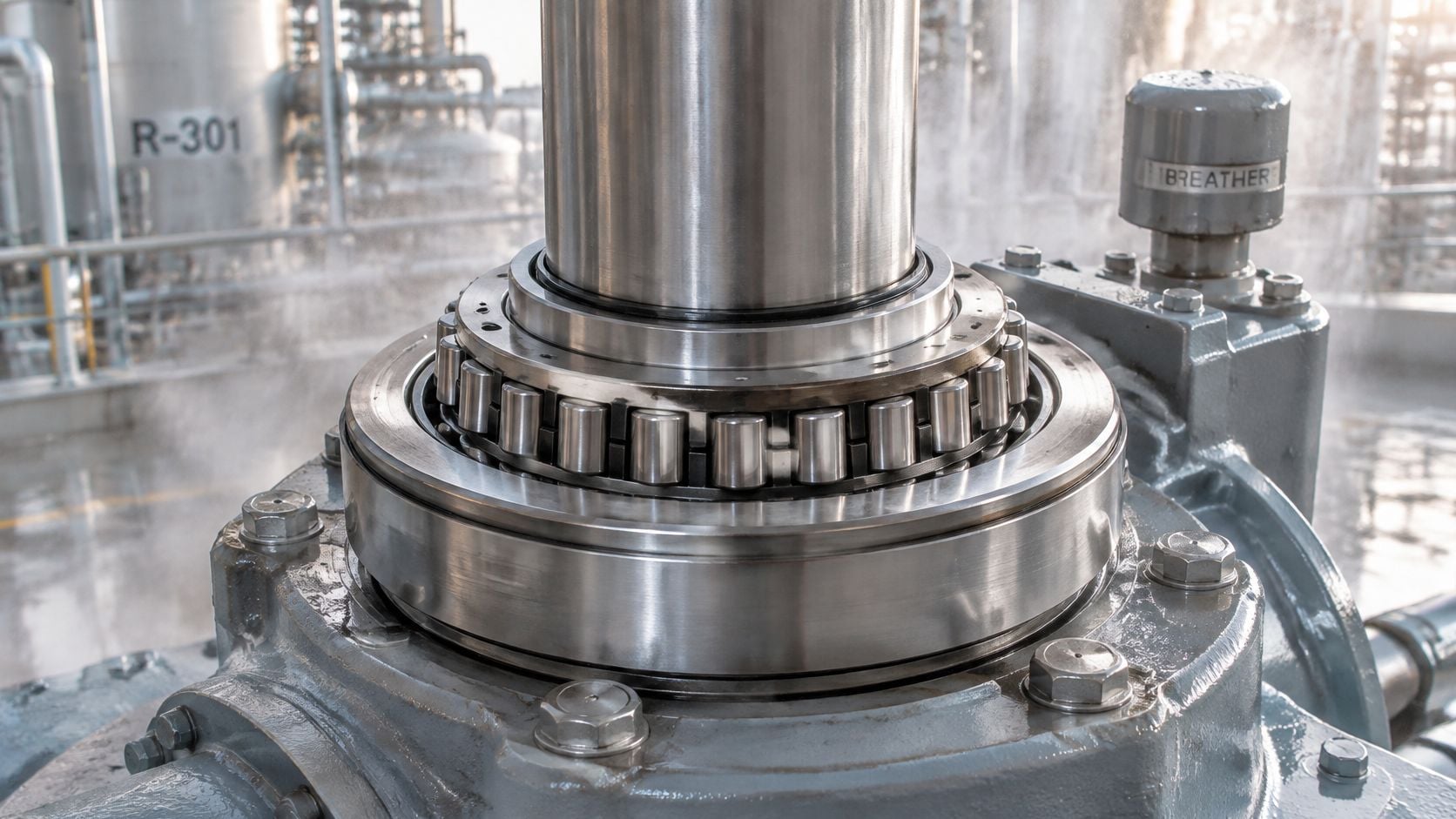
Make the thrust location a named route point
A monthly route is a starting proposal for this duty, not a universal safe interval. The technician collects readings under comparable speed, batch condition, and loading, with the measurement position marked permanently on the housing.
The work order needs these tags:
- Axial point: Housing vibration measured in line with the output shaft, using the same mounting method and acquisition settings.
- Cap-to-sump temperature: Bearing-cap temperature recorded alongside sump temperature and operating state.
- Oil debris: A repeatable patch examination or laboratory sample, taken from a representative location.
At the next planned stop, maintenance rechecks cold end float using the installation measurement method. A different shaft temperature or push-pull force can make an apparent change difficult to interpret.
Alarm logic responds to a sustained cap-to-sump temperature rise rather than an isolated reading after startup. A simultaneous increase in axial vibration, local temperature, and new metallic debris warrants inspection against the failure signatures, not a generic “bearing noise” work order.
That inspection decides whether the dynamic rating still means anything. The rating promises a life basis of one million revolutions, and a washer face that has lost hardness or taken brinelling marks no longer delivers that basis. Trend data tells you when to look; the hardness check tells you what the bearing can still carry.
Choose the interval from batch consequences
Contact ultrasound, which detects high-frequency structure-borne sound, can add sensitivity to friction changes before a clear temperature alarm. Readings still need a stable contact point, and an unfamiliar sound becomes a diagnosis only after comparison against a recorded baseline.
If loss of agitation stops a reactor batch or threatens product conformity, the thrust location belongs high in the asset criticality ranking. Continuous axial vibration and temperature monitoring may then suit the duty better than waiting for the next route, while protective shutdown functions stay armed as the last line of defense.
The route design should fit the broader condition-monitoring approach for mixers and agitators. SIX ERP's discussion of maintenance planning for small manufacturers also provides context for connecting machine observations to planned work.
The planning record should end with a clear decision: continuous monitoring, yes or no, supported by the consequence of failure and the expected time available to act.
Request a Free Reliability Assessment
A time-based bearing swap is defensible only when the operating duty is predictable, the raceways remain qualified, and lubricant delivery is dependable. Even then, the replacement interval needs support from inspection history rather than habit.
Where any of those three conditions fails, condition-based maintenance takes over: intervention scheduled from measured deterioration and failure risk. Sensors added to an unchanged replacement schedule change nothing.
Bring evidence to the maintenance decision
A structured review needs the rating sheet and the life calculation behind it, the cold end-float baseline, temperature and oil-debris trends, and photographs of damaged washers. Whatever the record lacks becomes an assigned inspection task, because a missing hardness value or an undocumented fit can mean the failed assembly was never correctly specified.
The review should produce concrete decisions:
- Rank the thrust location: Compare its production consequence and recurrence with other site failures.
- Approve the monitoring tags: Confirm the axial point, cap-to-sump temperature measurement, and debris check.
- Match inspection to the mechanism: Investigate load events, contamination, or support geometry according to the observed damage.
- Correct the specification: Document washer hardness, fits, acceptance criteria, and lubricant delivery instead of copying the failed parts list.
A replacement cage closes a repair task. A documented load check, qualified raceway, and verified lubricant path decide whether the repair lasts.
I would schedule the review while operations can still supply duty information and maintenance can preserve useful evidence. That timing lets the shutdown scope cover machine-face repair, instrumentation, or oil-path changes rather than another cage-only replacement.
Forge Reliability offers a free reliability assessment to review rotating-equipment failure risks and identify practical monitoring and maintenance changes. Visit Forge Reliability to request an assessment of the thrust bearing's load basis, raceway condition, lubrication path, and inspection strategy before the next teardown.