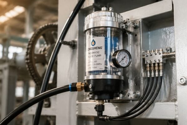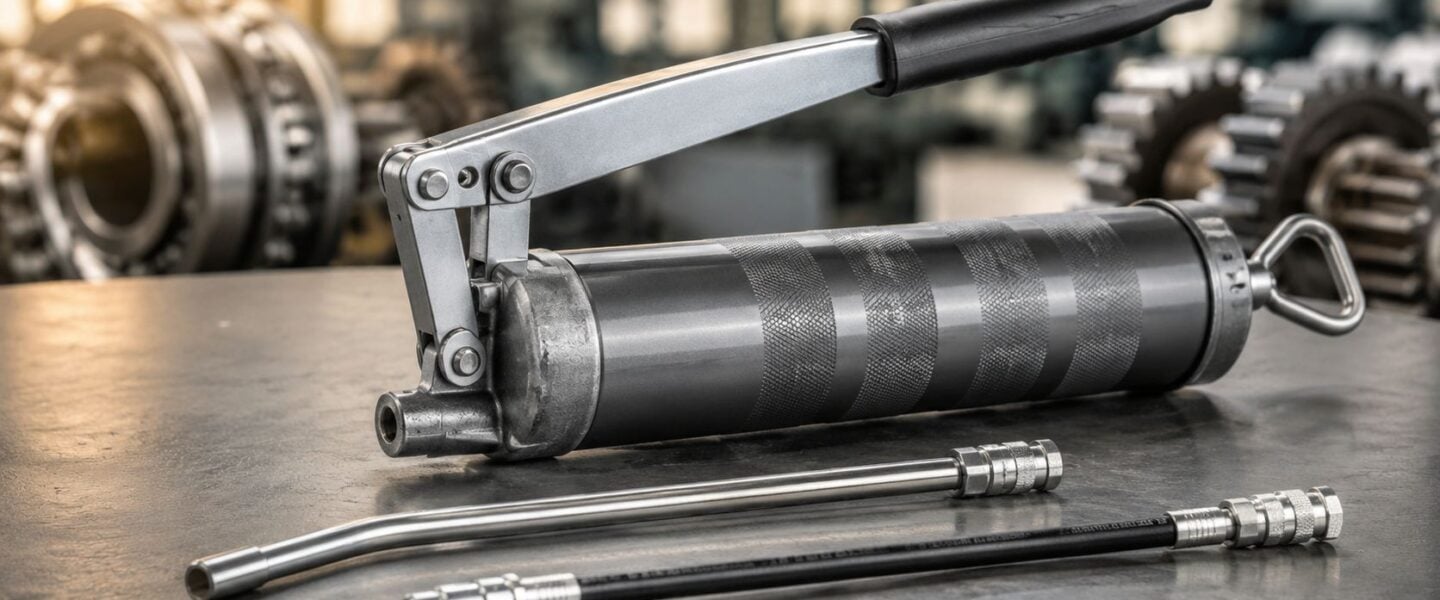
A lubrication route rarely fails because the technician forgot the grease gun. It fails because the last inch of the process was treated like a commodity. The wrong grease gun tube was loaded, the hose couldn't reach the fitting cleanly, the coupler leaked under pressure, or the gun airlocked after a cartridge change and nobody realized the bearing received nothing.
That chain of small errors shows up later as hot housings, noisy bearings, shortened relubrication intervals, and lost production. In a plant with motors, pumps, conveyors, gearboxes, fans, robotic cells, or mobile equipment, the grease gun tube sits at a control point between maintenance intent and actual lubricant delivery. If that control point isn't engineered, the lubrication program isn't engineered either.
A packaging line motor, a chemical skid pump, and an overhead crane trolley don't create the same access, pressure, contamination, or handling problems. Yet many plants still issue one generic grease gun setup and expect consistent results. That decision usually looks efficient in procurement and expensive in operations.
Table of Contents
- Deconstructing the Grease Gun Tube, Hose, and Cartridge
- Choosing Your Delivery Path Rigid Tubes vs Flexible Hoses
- Decoding Critical Specifications for Industrial Reliability
- Application-Driven Selection for Critical Plant Assets
- Installation, Inspection, and Root Cause Failure Analysis
- Integrating Grease Gun Strategy Into Your Reliability Program
Deconstructing the Grease Gun Tube, Hose, and Cartridge
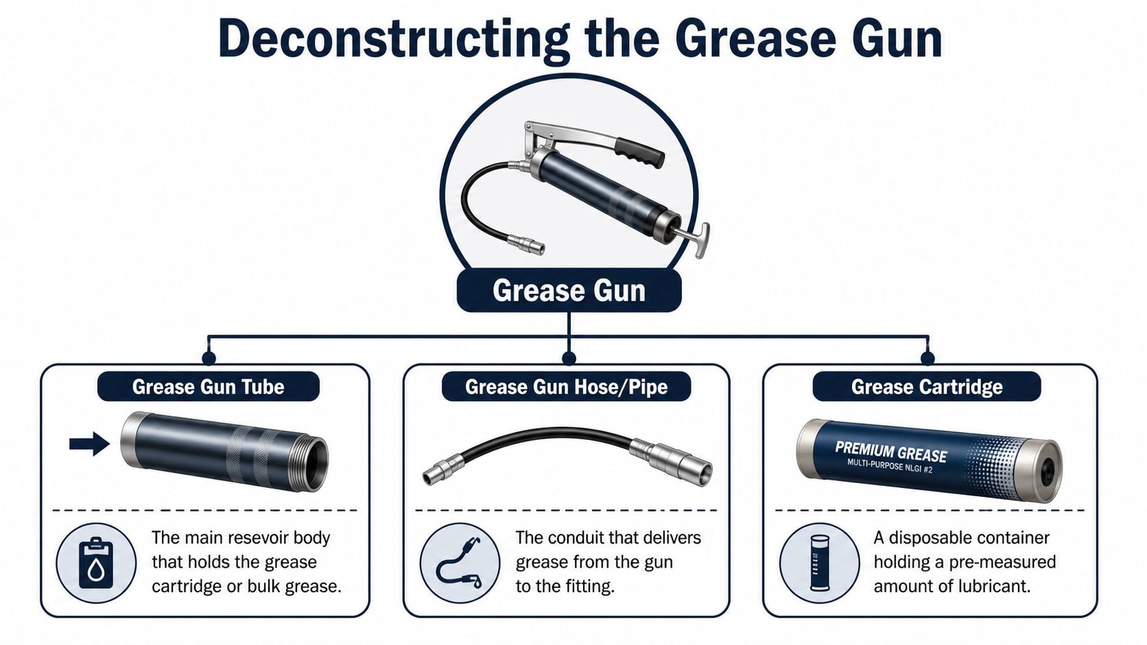
People use the phrase grease gun tube to mean three different things. In reliability work, that ambiguity creates purchasing mistakes, poor work instructions, and field confusion during breakdown response. A planner orders “tubes,” the storeroom issues cartridges, and the technician needed a delivery pipe or hose.
Why terminology errors create reliability failures
The simplest way to separate the parts is this. The cartridge is the disposable grease container. The barrel is the main body of the grease gun that holds the cartridge or bulk grease. The hose or rigid pipe is the delivery path from the gun to the fitting.
That matters because each part fails differently. Cartridge mismatch causes feed problems. Barrel damage affects sealing and follower travel. Hose or pipe issues create access problems, leakage, and poor connection at the lube point.
Practical rule: If a work order says “replace grease gun tube,” the task should specify whether the technician means cartridge, barrel, or delivery tube. Anything less invites the wrong spare.
In an automotive assembly environment, that distinction becomes operational fast. Robotic welding cells often have compact bearing locations and short maintenance windows. If technicians stock mixed cartridge sizes or incompatible delivery hardware, the lubrication route slows down and some points get skipped.
What each component actually does
The cartridge and barrel have to work as one sealed feed system. A standard 14 oz / 400 g cartridge is typically about 9-1/4 inches long and roughly 2-1/8 inches in diameter, while mini tubes are about 3 oz, around 5-1/2 inches long and 1-1/4 inches wide. When the wrong size goes into the wrong barrel, the follower can't seal correctly, vacuum breaks, air enters, and grease delivery becomes intermittent or stops entirely, as outlined in this guide to grease gun cartridge dimensions and fit.
A useful analogy is a fuel can and a fuel line. The cartridge stores the lubricant. The hose or rigid pipe delivers it. The barrel is the chamber that makes feed pressure possible. Confusing storage with delivery leads plants to solve the wrong problem.
For teams tightening their lubrication standards, equipment-specific procedure control is fundamental. Barrel size, cartridge format, hose type, and coupler style should sit inside the same approved setup matrix used for lubrication system standardization across plant assets.
Choosing Your Delivery Path Rigid Tubes vs Flexible Hoses
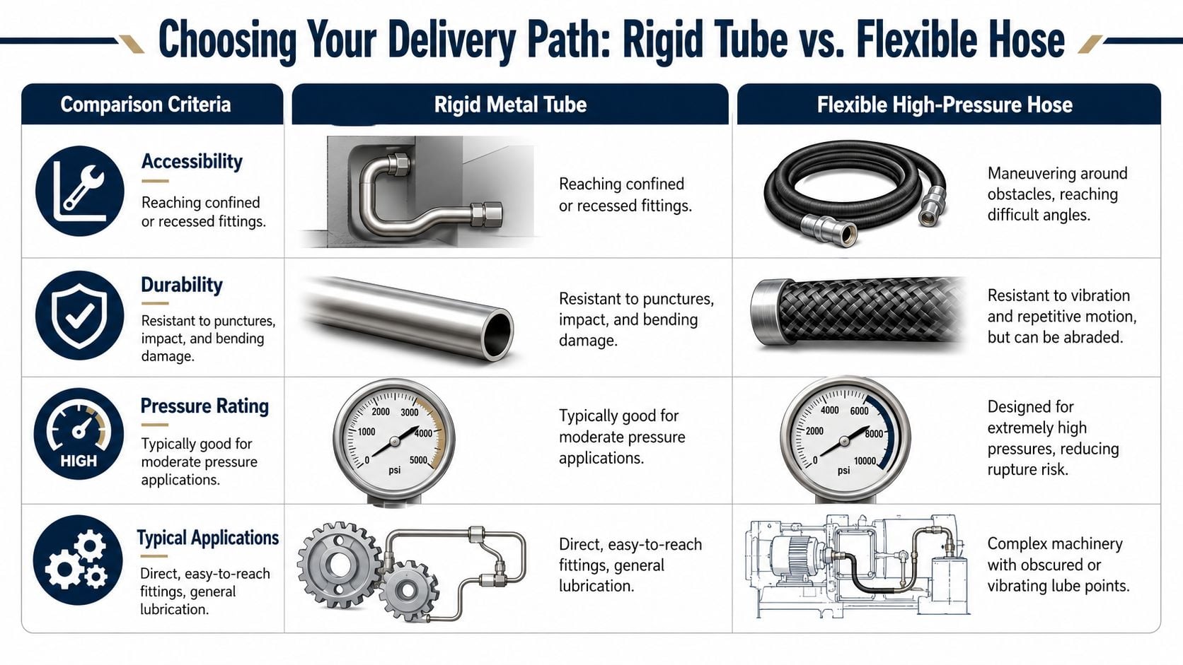
The delivery path changes technician behavior. If the lube point is easy to reach and visible, a rigid tube often gives better control. If the point sits behind guarding, under a motor base, inside a skid, or near a hot surface, a flexible hose usually prevents a missed task.
A chemical processing plant is a good example. Open-frame pumps and motors mounted at waist height can usually be lubricated with rigid tubes because the fittings are direct and visible. Gearboxes tucked inside containment skids are different. They may require the technician to approach from the side, below, or through a narrow opening. A rigid tube in that setting doesn't improve discipline. It encourages partial engagement, grease loss, and skipped bearings.
Where rigid tubes still make sense
Rigid tubes work best where access is straight, stable, and repeatable. They give the technician a more direct mechanical feel when engaging the coupler, and they resist puncture or crushing from casual contact in crowded maintenance carts or tool drawers.
They also suit routes where fittings are exposed and standardized. Common examples include electric motors on accessible bases, pillow block bearings along open conveyor runs, and pump bearings outside insulation or guarding zones.
A rigid tube is usually the wrong choice when the technician has to twist the gun body to match fitting angle. That posture reduces control and increases side loading at the coupler.
Where flexible hoses prevent missed lubrication
Flexible hoses solve a different problem. They separate hand position from fitting position. That matters on compact machines, vibrating assets, and installations where the operator must keep clear of pinch points or sharp edges while making the connection.
For recessed or hard-to-reach fittings, adapter selection is as important as the hose itself. Recessed (cup) extensions, right-angle couplers, and push-on 90° adapters are intended for fittings that can't be approached straight on. Without them, grease escapes at the interface, contaminants can enter, and technicians frequently miss lube points, as shown in this reference on adapters for recessed and angled grease fittings.
A lube point that can't be reached cleanly is not a valid PM task. It's a design problem disguised as a work order.
A flexible hose setup belongs in route planning, not just in the tool crib. Plants that improve route compliance usually define hose length, coupler type, and adapter needs by asset class inside their broader plant lubrication optimization standards.
Rigid Tube vs. Flexible Hose Key Selection Criteria
| Criterion | Rigid Tube | Flexible Hose |
|---|---|---|
| Accessibility | Best for direct, visible fittings with straight-on access | Better for buried, recessed, angled, or obstructed fittings |
| Control | Strong tactile feedback during coupler engagement | Better body positioning in tight spaces |
| Durability risk | Resists puncture and casual impact well | Handles motion and awkward geometry better, but can abrade |
| Safety | Can force awkward hand placement near equipment | Helps maintain distance from hot or cramped locations |
| Typical use | Motors, pumps, open conveyor bearings | Skids, gearboxes, enclosed machinery, compact assemblies |
Decoding Critical Specifications for Industrial Reliability
A technician can complete a PM on schedule, record the lube point as done, and still leave a bearing one failure step closer to damage. I see this in plants where the gun is specified, the grease is specified, but the tube or hose between them is treated like generic hardware. That delivery path is a control point. If it leaks, expands, traps air, or reacts badly to the environment, the task produces false confidence instead of grease where it belongs.
Three specifications decide whether the hardware supports reliability or undermines it. Pressure rating, internal flow path, and material compatibility.
Pressure capability and safety margin
Start with pressure rating, as hidden failure often begins there. A grease gun can generate more pressure than many teams expect, especially when a fitting is partially blocked, grease is cold, or the bearing relief path is poor. If the tube, hose, or coupler is operating too close to its limit, the failure may show up as a burst. More often, it shows up as a small leak at the connection, tube swell under load, or a coupler that will not stay sealed on the fitting.
That matters in reliability terms because the failure mode is misdelivery, not just hardware damage.
On the plant floor, the technician feels resistance, sees grease appear near the zerk, and assumes the cavity has accepted the charge. In fact, the grease may have exited at the weakest interface while the rolling elements stayed starved. On a fan motor, pillow block, or auxiliary pump bearing, that error shortens regrease interval effectiveness and pushes temperature and vibration upward without any obvious trigger in the PM record.
Pressure margin should be specified the same way you would specify margin on a seal, hose, or instrument line. Match the assembly to worst-case field conditions, not ideal bench conditions.
Inner diameter and grease movement
Internal diameter affects more than convenience. It changes resistance to flow, the effort required at the gun, and how consistently grease reaches the point after each stroke. Small passages can help with control, but they also raise flow resistance, especially with higher-viscosity grease, longer hose runs, or low ambient temperatures. Larger passages reduce restriction, but they can change how the gun feels in use and how predictable each shot is at the fitting.
This is why stroke count alone is a weak control method unless the full delivery assembly is standardized.
If one route uses a short rigid tube and another uses a longer flexible hose with a different internal diameter, the same number of strokes does not give the same field result. One setup may build pressure quickly and encourage the technician to stop early. Another may accept more grease before resistance is felt. On small electric motor bearings, that difference can mean the gap between correct replenishment and grease pushed into the windings or out through the seals.
For teams building precision lubrication tasks, the better practice is to document gun type, delivery hardware, coupler style, and target volume together inside the FMEA process for lubrication system failure modes. That turns a hand tool choice into a controlled variable tied to failure prevention and OEE.
Small bearings do not care whether the route was completed. They respond to whether the right grease volume actually crossed the fitting and entered the bearing.
Material selection and environment
Material selection decides whether the assembly stays trustworthy after months of actual use. Steel stands up well to impact, crushing, and rough handling in shops where tools are dragged across skids, dropped on concrete, or stored in crowded carts. In wet or corrosive areas, that same steel can become the source of seized threads, surface corrosion, and contaminated coupler interfaces if finish and cleaning practices are poor.
Repeated flexing creates a different failure path. In tight access points, a hose that is bent sharply on every PM route will eventually soften, kink, crack internally, or fail at the end connection. The bearing may not fail that day. The route starts taking longer, technicians use more force, coupler engagement gets inconsistent, and lubrication quality drops one work order at a time.
The right choice depends on the exposure at the asset. Paper machines, washdown packaging lines, hot process areas, and dirty bulk handling systems each impose different stresses on the delivery hardware. Reliability teams should specify tube and hose materials by route condition, contamination risk, and handling pattern. That is how a low-cost component supports repeatable lubrication, cleaner PM execution, and fewer avoidable bearing failures.
Application-Driven Selection for Critical Plant Assets
The right grease gun tube arrangement is decided at the asset, not at the storeroom shelf. Bearing type, fitting location, contamination exposure, grease consistency, temperature, and technician access all shape the best setup. The error many plants make is assigning one hardware combination to every lubrication task.

Food and beverage washdown lines
In food and beverage plants, washdown changes the decision. Bearings on conveyors, fillers, and packaging drives may sit in areas exposed to frequent cleaning and chemical contact. The grease gun tube setup has to resist contamination transfer and remain manageable with gloved hands in wet environments.
A poor choice here usually shows up as external leakage, dirty couplers, or inconsistent engagement at fittings that already see water exposure. Maintenance leaders should define hardware that can be cleaned easily and connected without excessive hand repositioning around guarding and drip zones. These asset decisions fit naturally within broader asset management practices for lubrication-dependent equipment.
Mining and mobile equipment
Mining and quarry equipment create a harsher combination. Shock, vibration, dust, and awkward machine geometry all work against precise lubrication. Grease fittings on mobile assets often sit behind guards, under articulation points, or near surfaces that collect abrasive contamination.
In this environment, durability matters, but access usually matters more. A setup that survives the toolbox but doesn't reach the fitting under realistic field posture isn't reliable. Flexible delivery hardware with the right coupler arrangement often protects the PM task from becoming a grease spill exercise.
A common failure mode on mobile assets is false completion. The technician reaches the area, engages imperfectly, pumps, sees grease outside the interface, and moves on. The task closes. The joint remains underlubricated.
Steel mill overhead cranes
Overhead cranes in metals and fabrication plants introduce a different constraint. Safe access often drives the selection more than anything else. When trolley or bridge components are lubricated from awkward elevations or from difficult platforms, longer flexible configurations may be needed so the technician can hold position and maintain coupler seal without overreaching.
For these assets, selection should answer three questions:
- Can the fitting be approached squarely: If not, specify the adapter at the same time as the hose.
- Can the technician hold seal under load: If the setup requires body twist or one-handed pumping, the route is unstable.
- Can the hardware stay clean between uses: Crane environments often carry dust, scale, and debris that can enter the connection point.
Plants usually improve reliability when they stop asking, “What grease gun does the site use?” and start asking, “What delivery path lets this exact bearing receive grease consistently?”
Installation, Inspection, and Root Cause Failure Analysis
A motor bearing fails two weeks after a PM route, and the work order shows it was greased on schedule. I see this pattern often. The route was completed, the handle was pumped, grease showed up somewhere, and everyone assumed the bearing received lubricant. The grease gun tube, hose, or coupler was the actual point of failure.
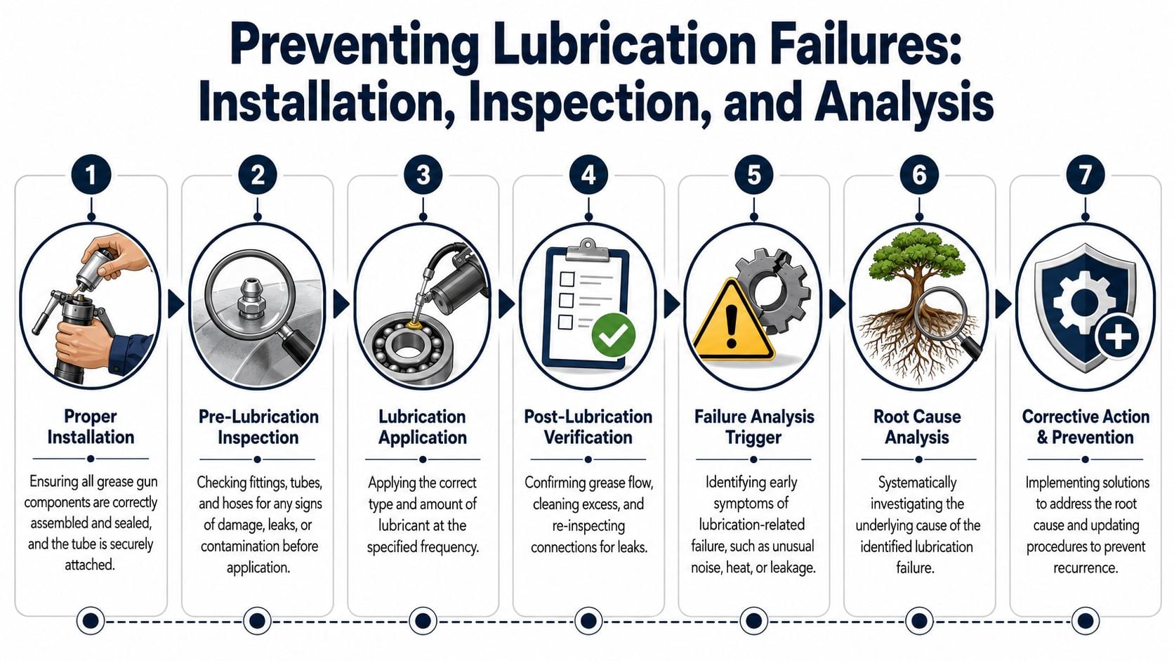
Installation steps that prevent false lubrication
Poor cartridge installation creates a hidden failure mode. The technician feels handle resistance, assumes grease is moving, and logs the task complete. The bearing sees nothing.
Air trapped after a cartridge change is a common cause. The fix is simple. Loosen the barrel, cycle the gun until grease appears at the threads, then retighten and confirm discharge before going to the asset. That bench check matters because it separates a loading problem from an equipment problem.
Use a repeatable installation sequence:
- Confirm cartridge and barrel match. A forced fit damages seals and creates feed problems that look like hose or coupler issues.
- Check follower travel before leaving the bench. If the follower hangs up, the gun will deliver inconsistently under field conditions.
- Prime the gun immediately after loading. Do not wait until the first lube point to discover trapped air.
- Prove grease discharge at the outlet. Handle resistance is not evidence of flow.
- Wipe the tube, hose connection, and coupler nose clean. Clean hardware reduces contamination transfer into the fitting.
If discharge was not verified after loading, the PM task was never under control.
That statement matters in reliability terms. In an FMEA, an unprimed gun creates a high-occurrence, low-detection failure mode. The operator believes the function was performed, but the asset remains underlubricated.
Inspection points that catch failure early
Inspection has to focus on failure mechanisms, not appearance. A grease gun can look serviceable in the toolbox and still fail at the fitting under pressure.
Check the delivery hardware for these conditions:
- Hose abrasion or kinking. This usually points to poor storage, poor routing during use, or repeated contact with guarding and structural steel.
- Tube loosening at threaded joints. Small leaks here reduce delivered volume and introduce air.
- Coupler wear. If the jaws do not hold squarely on the fitting, grease exits at the interface instead of entering the bearing cavity.
- Barrel thread damage or seal wear. These defects show up as chronic priming problems and erratic output.
- Contaminated coupler noses and hardened residue. Old grease traps grit, and that grit gets pushed into the zerk on the next shot.
- Damaged or plugged machine fittings. A blocked fitting can be misread as a gun problem unless the technician checks both sides of the interface.
On the plant floor, I treat coupler leakage as a reliability signal, not a housekeeping issue. Grease outside the fitting means either the seal failed, the fitting is blocked, or the approach angle is wrong. All three conditions degrade lubrication quality and waste technician time.
Troubleshooting common grease delivery failures
A short fault table helps crews diagnose the actual cause instead of swapping parts and hoping the symptom disappears.
| Symptom | Likely Cause | First Check | Reliability Risk |
|---|---|---|---|
| No grease output after reload | Trapped air after cartridge change | Re-prime the gun and confirm outlet discharge | Bearing receives no grease |
| Intermittent output | Seal damage, follower hang-up, cartridge mismatch | Check follower movement, seals, and cartridge fit | Underlubrication and false PM completion |
| Grease leaking at coupler | Worn coupler, blocked fitting, poor engagement angle | Inspect coupler grip and test fitting condition | Contamination, grease loss, incomplete fill |
| Hose exterior damage | Abrasion during route or bad storage practice | Inspect contact points and handling method | Sudden loss of delivery during PM |
| High pumping resistance with no bearing purge | Plugged fitting or hardened grease path | Verify fitting is open before adding force | Fitting failure, seal damage, missed lubrication |
Repeated failures on one route usually indicate a system weakness. The route may require the wrong hose length, the wrong coupler geometry, poor access design, or weak storage discipline between PM cycles. That is a maintenance system problem tied directly to OEE, because missed lubrication raises failure frequency, extends downtime, and adds repeat work.
The right response is documented analysis, not guesswork. Use a formal root cause analysis process for lubrication failures to connect the symptom at the grease gun to the bearing failure mode, the PM method, and the control gap that allowed false completion. Plants that already track equipment condition, PM compliance, and lube-tool history under broader industrial asset management tips usually find these patterns faster because the evidence is easier to trace across shifts and asset classes.
Integrating Grease Gun Strategy Into Your Reliability Program
Plants often treat grease guns as consumable maintenance accessories. That mindset creates variation where consistency is needed most. If different crews use different barrels, cartridges, hoses, and couplers for the same asset class, lubrication quality depends on who happened to be on shift.
A reliability program should standardize approved configurations by asset type, access condition, and lubrication task. That doesn't mean one universal grease gun. It means a controlled list of acceptable combinations and a clear rule for where each one belongs. Motors on accessible bases may use one setup. Compact gearbox banks may use another. Mobile equipment may require a third.
Standardization and storage discipline
Storage practices deserve the same rigor. Grease cartridges should be stored upright to reduce oil bleed. A cartridge left in a depressurized gun should be stored horizontally in a cool, clean, dry area. Otherwise, oil can migrate, the remaining grease can harden, and discharge becomes inconsistent, as noted in this guidance on grease cartridge storage and separation control.
That point matters in plants where guns sit loaded between weekly or monthly PM cycles. A gun can look ready and still deliver separated lubricant inconsistently. The result is a dangerous illusion of control.
A plant-wide standard should cover at least these items:
- Approved hardware by asset class. Match barrel, delivery path, and coupler to machine access and environment.
- Storage instructions. Include loaded and unloaded conditions, depressurization, and cleanliness controls.
- Calibration expectations. Define how teams verify shot volume for critical bearings.
- Inspection ownership. Assign responsibility for tool condition before route execution.
Linking lubrication hardware to asset management
This is also where lubrication details should connect to CMMS records, PM job plans, and FMEA documentation. A lube task should specify more than grease type and interval. It should define access method, hardware requirements, and failure symptoms that indicate the task wasn't completed correctly.
Operations leaders trying to tighten this discipline can also borrow from broader industrial asset management tips that emphasize identification, traceability, and control across equipment populations. The same logic applies to lubrication hardware. If the plant can't identify which setup belongs to which asset, it can't manage reliability consistently.
The phrase “grease gun tube” sounds minor. In practice, it sits at the intersection of PM execution, contamination control, technician ergonomics, and bearing life. Plants that engineer that intersection usually get fewer missed lube points, fewer false completions, and fewer repeating lubrication-related failures. Teams that want those controls embedded in the daily system should treat them as part of the site's broader operations and maintenance reliability framework.
A free reliability assessment from Forge Reliability can identify where lubrication hardware selection, storage practices, PM task design, and failure analysis are creating hidden bearing risk in a facility. For plants dealing with repeat lubrication failures, inconsistent routes, or unexplained bearing losses, that assessment is a practical starting point for stronger control.