The call usually comes when production is already behind. A motor trips, a pump support bearing starts screaming, or a conveyor pulley housing is too hot to touch. The part itself may be inexpensive. The event never is.
For reliability engineers, maintenance managers, and plant operations leaders, the failure of bearings is rarely about the bearing alone. It's about the lost batch in a food plant, the missed pour in a cement line, the overtime callout, the rushed installation, and the nagging question after restart: why did this happen again on the same asset?
Most plant teams don't need another generic list of bearing problems. They need a practical way to connect physical damage, operating symptoms, and diagnostic evidence into a root cause decision. That's where bearing reliability work either gets better or stays stuck in replacement mode.
Table of Contents
- The True Cost of Bearing Failure
- The Anatomy of Premature Bearing Failure
- Decoding Diagnostic Signals from Your Equipment
- Interpreting Vibration Spectra and Waveforms
- A Stepwise Guide to Root Cause Failure Analysis
- Proactive Strategies for Bearing Reliability
- Build a More Reliable Plant Starting Today
The True Cost of Bearing Failure
A night-shift failure on a critical process pump usually unfolds the same way. Operators notice rising noise first. Maintenance confirms increased temperature or vibration. Then the team scrambles for a spare, removes guards, locks out the equipment, and starts pulling a bearing that should never have failed that early.
The replacement part doesn't define the cost. The interruption does. In many plants, the bearing event becomes a production event, a labor event, and sometimes a safety event because the repair happens under pressure. That's why leaders who want durable savings usually look beyond parts spend and into planning, precision work, and recurring defect elimination. A stronger reliability program often starts with the same question raised in broader maintenance cost reduction strategies: which failures are unavoidable, and which ones keep returning because the system allows them to?
A recurring bearing issue in a blower, fan, or conveyor is almost never just “bad luck.” It usually points to a controllable cause such as lubrication practice, contamination ingress, shaft alignment, poor fit-up, or installation damage. On the plant floor, that distinction matters. If the team treats every failed bearing as normal wear, they'll keep replacing symptoms. If they treat it as evidence, they can fix the conditions that created it.
Practical rule: A failed bearing is a report from the machine. The raceways, grease, seals, housing fits, and vibration pattern all tell part of the story.
A cement plant offers a familiar example. A mounted bearing on a clinker conveyor fails during a high-demand run. The spare gets installed quickly, but the housing cavity is still dirty, the shaft surface still has wear marks, and grease is added by feel instead of specification. The line restarts, but the next failure is already in motion.
The Anatomy of Premature Bearing Failure
Why most bearings fail early
The first lesson for any team studying the failure of bearings is simple. Most bearings don't die from honest old age. According to industrial bearing failure data, less than 30% of bearings in industrial applications ever reach their theoretical fatigue limit, while over 70% fail from preventable external factors such as poor fitting, improper lubrication, contamination, or misalignment. The same source notes that a single $50 bearing failure can cost a facility $25,000 to $50,000 per hour in lost production.
That's why failure mode identification matters so much. A plant can't improve what it lumps into one bucket called “bearing bad.” The physical damage pattern tells the team whether the asset was overloaded, starved of lubricant, contaminated, installed incorrectly, or forced to run with poor geometry. Load direction matters too, especially where teams confuse radial and thrust demands on a machine. On overhung fans, mixers, and vertical pumps, the distinction between force paths becomes critical, and a solid grasp of radial versus axial load behavior often explains why the same bearing position keeps failing.
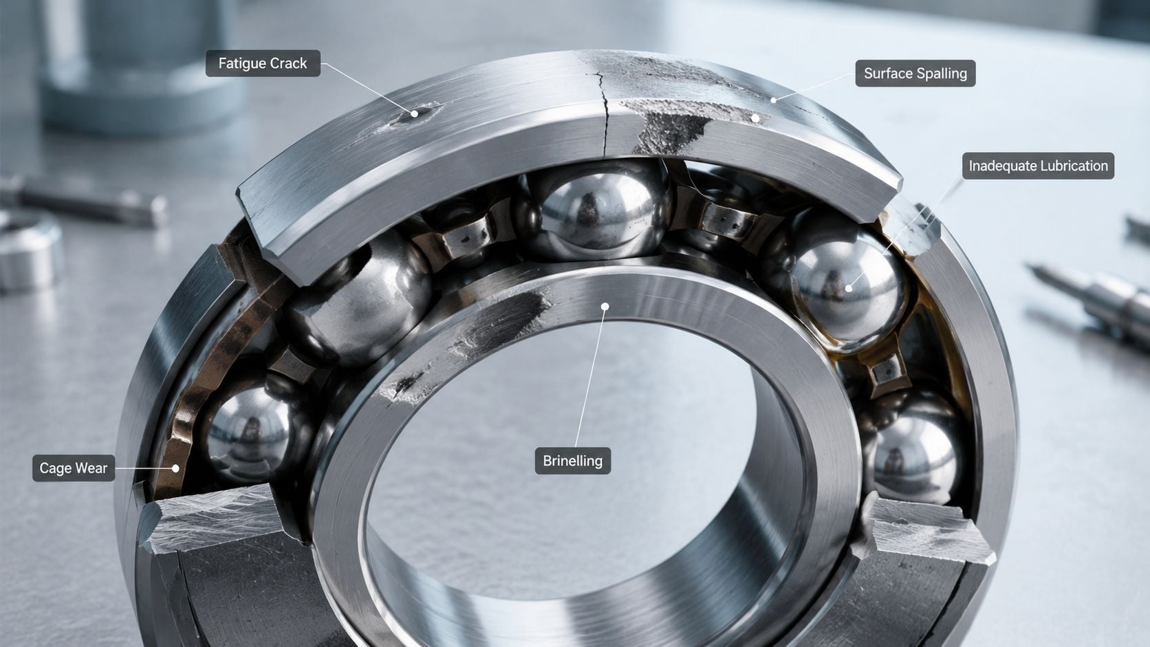
The seven failure signatures
Fatigue failure is what many people imagine first. Repeated stress creates subsurface cracks that eventually break through the raceway surface. The team sees flaking, spalling, or localized pits. If fatigue is the true end-of-life mode, the pattern is usually progressive and tied to loading history, not one installation event.
Lubrication failure looks different. Surfaces lose their separating film, metal contacts metal, and the bearing starts generating heat and distress quickly. Smearing, discoloration, wiped surfaces, and blue or brown heat tint often show up. Grease may appear hardened, dry, or contaminated.
Contamination leaves evidence in the form of abrasive wear, fine scratching, denting, and noisy surfaces. Dirt, process dust, water, and cleaning chemicals don't need much access to do damage. Once particles enter the contact zone, they indent raceways and rolling elements, then the bearing begins failing from the damage those particles created.
Bearings often fail in layers. A contamination problem starts the damage, poor lubrication accelerates it, and misalignment finishes the job.
Misalignment produces uneven load distribution. One side of the raceway carries more stress than it should. Edge loading, skewed wear patterns, cage distress, and increased running temperatures are common clues. In belt-driven assets, this often traces back to soft foot, pipe strain, base distortion, or coupling geometry that was never corrected after maintenance.
Improper mounting is one of the most preventable forms of damage. If a technician hammers on the wrong ring or forces the bearing over an interference fit without proper heating or tooling, the raceways may be bruised before the machine ever runs. Those brinell marks become stress risers and later show up as repeating defect-related vibration.
Electrical erosion usually appears in motors, variable speed drive applications, and electrically isolated systems that are not isolated. Arcing creates frosted or washboard-like raceway damage. The bearing may sound rough even when grease condition looks acceptable.
Corrosion is common in washdown and humid environments. In a food processing plant, for example, a conveyor tail pulley bearing near a sanitizing station may ingest moisture during repeated cleanup cycles. The team may first notice brown staining, then rough rotation, then surface distress where corrosion pits became fatigue initiation points.
A useful field check is to match what the team sees with what the machine was doing just before failure:
| Observed clue | Likely direction of investigation |
|---|---|
| Blue discoloration and hardened grease | Lubrication problem or excess heat |
| Fine scratches and dents | Contamination ingress |
| Localized edge wear | Misalignment or poor fit geometry |
| Repeating indentations | Mounting damage or particle denting |
| Fluting or washboard pattern | Electrical discharge |
| Rust staining or etched surfaces | Moisture or chemical attack |
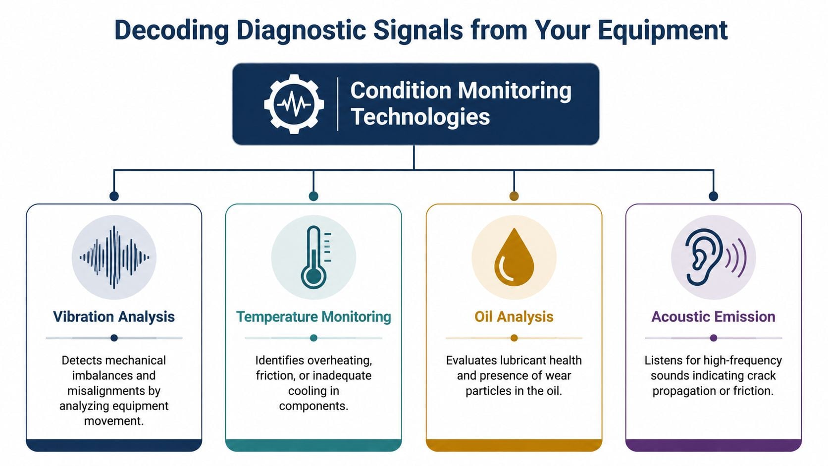
Decoding Diagnostic Signals from Your Equipment
Not every diagnostic method sees the same thing at the same time. That's why some teams miss early bearing damage even though they're “doing condition monitoring.” They're often using one method well, but using it for the wrong failure stage.
Choosing the right signal for the failure mode
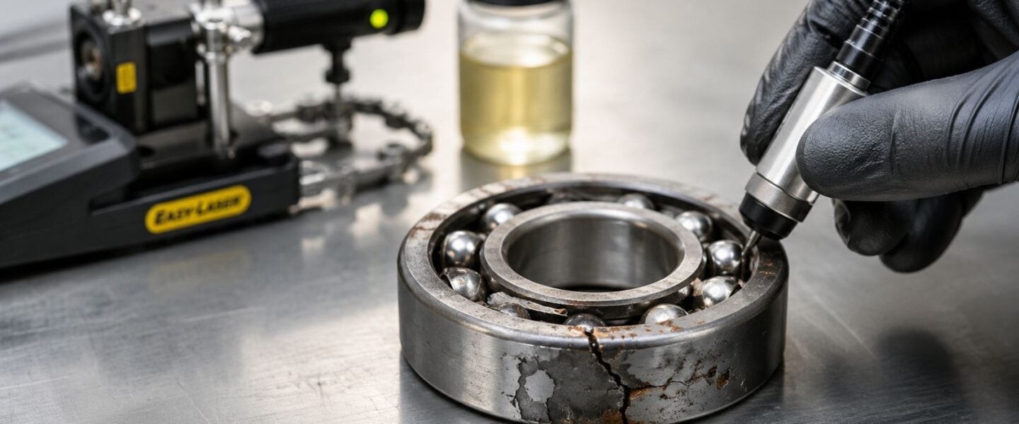
Under cyclic loads, the most common observed bearing failure modes are wear and fatigue, often showing up as flaking and cracks, and vibration analysis, oil analysis, and thermography are essential for early detection. That matters because each method responds to a different physical change inside the machine.
Vibration analysis is usually the strongest all-around tool once surface damage begins to develop. It detects changes in dynamic response. If the outer race has a localized defect, the sensor can capture repeated impacts at a predictable frequency. If misalignment is forcing the bearing to carry uneven load, the overall pattern often shifts before the bearing is visibly damaged.
Oil analysis and grease inspection are especially useful when the team needs to know what's happening inside the contact zone and lubricant system. Wear particles, moisture, viscosity changes, and contamination tell the story earlier than teardown will. In circulating oil systems, this is one of the clearest ways to separate a lube problem from a pure mechanical geometry problem.
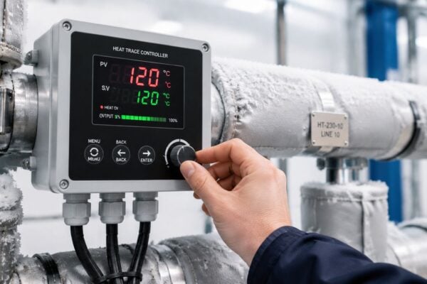
Thermography shows consequence rather than first cause. Temperature rises when friction, load, poor lubrication, or cooling problems are already affecting the asset. That doesn't make it weak. It makes it useful for confirmation, screening, and prioritization. In a power generation plant, a support bearing on an auxiliary fan or turbine train may show abnormal thermal growth before operators hear anything unusual.
Acoustic monitoring and ultrasound often catch friction-related changes very early, especially in lubrication work. High-frequency sound can reveal a starving bearing before vibration routes show a clear fault pattern. That's why teams building a practical lubrication program often rely on ultrasonic bearing monitoring and acoustic lubrication methods to avoid both under-greasing and over-greasing.
What each method sees first
A good program doesn't ask which technology is best in general. It asks which technology answers the specific diagnostic question in front of the team.
- If the concern is lubricant condition, oil analysis or ultrasound usually gives the earliest actionable answer.
- If the concern is raceway damage or mounting-related defects, vibration becomes the primary tool.
- If the concern is thermal loading, infrared screening helps confirm severity and identify which assets need immediate attention.
- If the concern is intermittent distress, combining waveform data with acoustic checks often reveals a problem that point-in-time temperature readings miss.
A practical example comes from a high-speed paper machine roll bearing. The route technician notices no obvious temperature increase, but ultrasonic readings trend upward and the grease sample shows contamination. That sequence points the team toward seal integrity and lubricant condition before visible bearing damage turns into a shutdown.
The best diagnostic teams don't collect more data than they need. They collect the data that answers the next decision.
Another useful habit is to think in terms of failure progression. Temperature is often late. Lubricant condition is often early. Vibration becomes decisive when damage creates repeatable mechanical events. When those signals are interpreted together, the plant stops guessing and starts isolating real causes.
Interpreting Vibration Spectra and Waveforms
For most rotating assets, vibration is where bearing diagnostics move from suspicion to evidence. A temperature gun can tell the team a housing is hot. A grease sample can show contamination. A vibration spectrum can often tell them whether the problem is imbalance, misalignment, looseness, gear interaction, or an actual rolling element bearing defect.
What the spectrum is actually telling the team
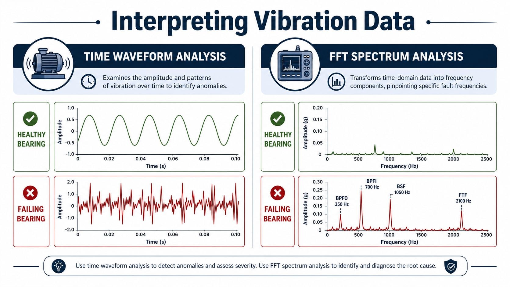
The time waveform shows how vibration changes moment by moment. This view is useful for spotting impacts, looseness, modulation, and repeating events. A healthy bearing position often produces a relatively stable pattern. A damaged bearing starts generating spikes or irregular bursts as the rolling elements strike a defect.
The FFT spectrum converts that motion into frequency components. Using this, the team observes whether energy is concentrated at running speed, harmonics of running speed, bearing defect frequencies, or gear-related frequencies. That's why a maintenance manager reviewing reports on a motor-driven pump should be comfortable with basic spectrum logic, even without becoming a specialist. A solid primer on vibration analysis of motor behavior helps connect those patterns to field decisions.
Here's the practical interpretation used on the plant floor:
| Pattern in data | What it often suggests |
|---|---|
| Strong 1x RPM peak | Rotor imbalance |
| 2x RPM and related harmonics | Misalignment, especially coupling-related |
| Broad high-frequency energy | Bearing distress, lubrication issue, or surface damage |
| Distinct defect frequencies with harmonics | Localized bearing fault |
| Sidebands around peaks | Modulation from looseness, load variation, or progressing damage |
Reading fault patterns in a real machine
Consider a gearbox in a steel mill. Operators report increased noise on one stand, and the team wants to know whether the problem is a gear mesh issue or a bearing inside the reducer. The distinction matters because the repair scope, outage duration, and spare planning are completely different.
A bearing outer race defect often creates repeated impact signatures tied to the bearing geometry and shaft speed. In the time waveform, the analyst may see evenly spaced impact events. In the spectrum, those impacts can show up as defect-related peaks with harmonics. As the defect worsens, the noise floor often rises because the impacts become less clean and more destructive.
Misalignment looks different. The spectrum may show increased 2x running speed and a pattern influenced by coupling condition and machine geometry. The waveform is often more sinusoidal than impact-driven. If the gearbox also has looseness, the harmonics become more complex and the phase behavior may point the team toward structural or fit problems rather than an isolated bearing fault.
A vibration spectrum doesn't identify “bad bearing” in the abstract. It identifies the mechanical event repeating inside the machine.
A few practical distinctions help during review meetings:
- Bearing fault frequencies suggest damage on a raceway or rolling element. These are especially convincing when paired with impacting in the waveform.
- Harmonics often mean the fault is developing, not just starting. Repeated impacts are becoming stronger and less isolated.
- Sidebands suggest modulation. In plain terms, something about load or interaction is shaping the signal. That may involve looseness, cage effects, or nearby mechanical components.
- A clean 1x issue usually points the team away from the bearing and toward balance.
The common mistake is jumping straight from “high vibration” to bearing replacement. That wastes outages. It also hides the underlying issue. If the root problem is pipe strain on a pump, a soft foot condition under a motor, or looseness in a pedestal, the next bearing will inherit the same stress.
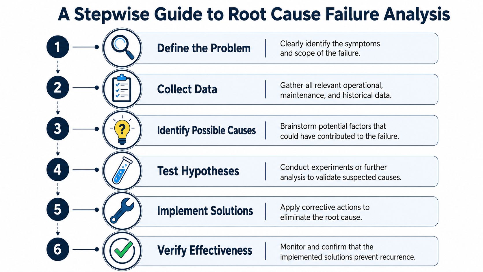
A Stepwise Guide to Root Cause Failure Analysis
A failed bearing should trigger an investigation, not just a work order closeout. Too many plants stop at the symptom because the asset is already back in service. That's how repeat failures become normal.
Start with evidence, not assumptions
A useful root cause process begins by locking down the facts before opinions take over. The team needs operating condition, failure timing, lubrication history, installation records, vibration data, thermal data, photos of as-found condition, and physical evidence from the removed components. Without that, the discussion turns into memory and preference.
One fact deserves immediate attention. Approximately 80% of all bearing failures in industrial rotating equipment are directly caused by improper lubrication, including insufficient quantity, incorrect lubricant, or contamination, and addressing lubrication is the highest-impact action for improving bearing life. That doesn't mean every failure is a grease problem. It means lubrication should be checked early, every time, because it's the most likely path to the answer.
A strong investigation usually follows this sequence:
- Define the failure clearly. Was the first symptom heat, noise, vibration, grease purge, seal leakage, or trip event?
- Protect the evidence. Keep failed parts, grease samples, and photos before cleanup removes clues.
- Map the failure mode. Match the physical damage to a likely mechanism such as contamination, misalignment, poor mounting, or electrical erosion.
- Test the obvious causes first. Verify lubricant type, quantity, relube interval, seal condition, fit tolerances, and alignment.
- Ask why the condition existed. A contaminated bearing may really be a bad seal, poor washdown practice, or missing housing inspection step.
- Change the system. If the process doesn't change, the failure will return.
For teams that need a structured method after teardown, a practical reference on bearing, gear, and seal failure interpretation helps connect damage patterns to root causes without relying on guesswork.
A practical decision path on the plant floor
Take a motor-pump set in a chemical plant. The route shows rising acceleration and a rough sound at the drive-end bearing. The team replaces the bearing during a short outage, then sends the removed part for inspection. The outer race shows localized distress and the grease is dark with fine particulate.
That evidence supports several hypotheses, but not equally.
- If the grease is wrong or degraded, the team investigates storage, contamination control, relube interval, and application quantity.
- If particle denting is visible, the team checks seals, breathers, housing cleanliness, and nearby washdown or dust sources.
- If mounting marks are present, the team reviews installation method, heating practice, shaft fit, and whether force was applied through the rolling elements.
- If vibration showed defect frequencies plus broadband noise, contamination plus surface distress becomes more likely than pure imbalance.
A short 5-Why sequence often sharpens the answer:
| Symptom | Why | Next why |
|---|---|---|
| Bearing failed early | Raceway damaged | Why was the surface damaged? |
| Surface damaged | Abrasive particles present | Why did particles enter the bearing? |
| Particles entered | Seal ineffective | Why was the seal ineffective? |
| Seal ineffective | Washdown forced moisture and debris past it | Why was that exposure not controlled? |
| Exposure not controlled | No standard for shielding or post-wash inspection | Corrective action belongs in procedure, not just repair |
Replace the bearing if needed. Eliminate the entry path if the team wants the problem gone.
The strongest root cause work changes standards, routes, inspection points, and precision practices. It doesn't end with “bearing replaced and asset returned to service.”
Proactive Strategies for Bearing Reliability
Plants don't reduce bearing failures by talking more about reliability. They reduce them by tightening a handful of work practices that directly attack the known failure mechanisms. The return usually comes from fewer repeat jobs, fewer secondary failures, and less production disruption.
Precision practices that stop repeat failures
Lubrication discipline is the first lever. A bearing needs the right lubricant, in the right amount, at the right interval, under the actual operating conditions. Too little lubricant collapses the separating film. Too much creates churning, heat, and seal stress. Greasing by habit doesn't work. Precision lubrication requires clear standards, contamination control, labeled products, protected storage, and a method to verify condition instead of assuming it.
Contamination control comes next because dirt and water undo good lubrication quickly. Contamination and improper mounting are leading causes of bearing failure, and contamination creates abrasive particles that erode raceways while mounting impacts can create brinelling that later becomes a fatigue origin. That's why plants with dusty or wet service need better sealing, cleaner installation practices, and housing inspections that are enforced.
Proper mounting is paramount. Bearings should be installed with the correct force path and correct tools. Induction heating, clean fits, measured interference, and controlled seating prevent damage that hammers and improvised methods create in seconds.
A practical field checklist looks like this:
- Protect the lubricant. Keep grease containers sealed, clean tools before use, and don't mix products unless engineering has approved it.
- Verify fits and surfaces. Inspect shaft condition, housing bores, shoulders, and sleeves before installation.
- Install with controlled force. Apply force only through the ring being fitted. Don't transmit installation force through rolling elements.
- Confirm alignment after work. Couplings, bases, and pipe strain can shift during reassembly.
- Set inspection points by consequence. Critical assets need tighter monitoring than non-critical utility drives.
An aggregate site is a strong example because conditions are unforgiving. In aggregate mining and cement production, lubrication issues account for 70 to 80% of bearing failures in harsh environments with mud, water, dust, and salt ingress, and recommended countermeasures include sealed bearings, compressed-air cleaning, and automated centralized lubrication systems according to guidance for mounted bearing failure in aggregate mining. In that setting, proactive investment isn't a luxury. It's basic operational control.
Designing a program that operations will support
The best reliability strategies fit the way the plant runs. If a lubrication route requires access during full production but the machine is boxed in by guards and heat, the route won't stay precise. If the alignment standard is excellent on paper but mechanics don't have enough outage time to correct soft foot, the standard won't hold.
That's why the most effective programs build around practical decisions:
- Which bearings are critical enough for regular vibration and lubricant checks
- Which environments need upgraded sealing or housing redesign
- Which assets justify automatic lubrication because manual access is poor
- Which failure reports must include physical evidence before closeout
A packaging line in a washdown food plant needs a different strategy than a quarry conveyor. One fights moisture, chemicals, and corrosion. The other fights abrasive dust and relube access. The principle is the same. Match the preventive strategy to the dominant failure path.
There's also a useful broader lesson from life-safety engineering. Redundancy and reliability don't happen by accident. A thoughtful reference like DLG Electrical's guide to smoke detectors is useful because it shows the same systems principle that applies in plants: critical functions become more dependable when detection, backup, and maintenance are designed into the process rather than added after failures.
Reliability improves when the plant makes the right action the easy action.
Alarm limits should follow the same logic. If thresholds are too loose, the team finds problems late. If they're too sensitive, the plant gets flooded with nuisance alerts and stops trusting the system. Good limits are tied to asset criticality, operating regime, and known failure behavior. They should trigger a defined response, not just another unread notification.
Build a More Reliable Plant Starting Today
The failure of bearings is often described as ordinary plant wear. That mindset keeps teams reactive. Most recurring bearing events are better understood as evidence of something controllable in the machine, the maintenance process, or the operating environment.
The practical path is straightforward. Identify the physical failure mode. Match it to the right diagnostic signal. Read vibration and lubrication evidence carefully enough to separate symptom from cause. Then change the work practice, hardware condition, or inspection method that allowed the defect to develop.
For plant leaders, that shift is larger than bearing life alone. It improves outage quality, planning accuracy, spare usage, and confidence between operations and maintenance. The same decision discipline that helps a team choose between custom development and standardization in digital programs, such as the AI tooling decision guide, also matters in reliability work. Plants get better results when they choose repeatable systems over one-off fixes.
A more reliable facility doesn't start with replacing every problem asset. It starts with tightening the decisions around the assets that fail too often, cost too much to lose, or keep forcing unplanned work into the schedule.
A no-cost reliability assessment from Forge Reliability can help identify why bearing failures keep recurring in critical assets, where diagnostic gaps exist, and which corrective actions will deliver the fastest reduction in unplanned downtime.