
A separator's magnetic level gauge can show a calm, credible reading while the process is already moving toward an upset. The external flags may be aligned, the chamber may look clean from the operating floor, and the control room may have no alarm. Yet a stuck float, blocked connection, damaged magnet, or changing fluid density can leave the display reporting yesterday's level.
That's why magnetic level gauges deserve treatment as reliability equipment, not merely passive sight indicators. They're valuable because they preserve the process boundary and provide local visibility in severe service, but their simplicity can create false confidence. A sound program combines correct specification, disciplined commissioning, independent verification, defined proof testing, and inspection intervals that reflect corrosion, fouling, density changes, and consequence of failure.
Table of Contents
- When a Magnetic Level Gauge Lies to You
- How Magnetic Level Gauges Actually Work
- Selecting the Right Gauge for Your Service
- Installation and Commissioning Best Practices
- Failure Modes That Trip Up Even Experienced Teams
- Integrating Gauges Into a Predictive Maintenance Program
- A Real-World Example and Your Next Step
When a Magnetic Level Gauge Lies to You
A three-phase production separator was operating at 480 psig and 180°F. Its magnetic level gauge showed a steady interface for nine days. A clamped-on guided wave radar check then showed the interface drifting 3.5 inches toward the water weir, while the operator-facing indication remained unchanged.
The plant had trusted the visual reading because nothing looked abnormal. The water dump valve wasn't cycled, the separator continued operating, and emulsion began carrying over into the sales crude. The gauge hadn't failed dramatically. It had entered a silent-failure state, where the display remained plausible while the process condition moved elsewhere.
The decision chain that concealed the problem
The failure became understandable after the maintenance review:
- Single-technology dependence: No independent level measurement challenged the magnetic indication during normal operation.
- Missing proof test: The maintenance plan treated the gauge as a local indicator and didn't assign a functional test interval.
- Post-wash false confidence: A recent chemical wash had left the float chamber dry. The chamber looked serviceable, but the float's mechanical condition and magnetic response hadn't been demonstrated under operating conditions.
- No trend reconciliation: Operators didn't compare the interface reading with water-dump activity, density behavior, or the downstream emulsion trend.
A magnetic level gauge's external display can look normal when the float is stuck on fouling, resting against debris, or no longer tracking the actual interface. A transmitter mounted on the outside rail can extend the signal into the control system, but it can't make a mechanically immobilized float accurate.
Practical rule: A believable local indication isn't proof of a healthy measurement path.
The investigation should have examined the contributing factors, not just replaced the gauge. A structured contributing factors analysis would have connected the instrument fault to missing verification, washout practices, operating assumptions, and the absence of a defined response to level disagreement.
For critical separators, the reliability framework is straightforward. Use an independent reference when the consequence warrants it, assign proof-test intervals according to the instrument's safety role, establish condition-monitoring triggers, and reconcile the gauge against density and interface trends. Silent drift is usually more dangerous than an obvious loss of indication because the plant keeps making decisions based on a reading nobody has challenged.
How Magnetic Level Gauges Actually Work
A magnetic level gauge uses a sealed vertical chamber connected to the vessel so the liquid inside the chamber follows the vessel level. The float behaves like a fishing bobber in a still pond. As the process level rises, buoyancy lifts the float. As the level falls, the float descends.
Inside that float is a magnet assembly. The float moves inside a non-magnetic chamber, while an external indicator rail carries magnetic flags, flaps, or a follower. The magnetic field crosses the chamber wall and changes the position or color of the external indicator. Operators can therefore read the level without exposing a glass tube or opening the pressure boundary. The operating principle is based on magnetic coupling between the internal float and the external display, as described in this magnetic level indicator working-principle reference.
What the chamber does well
The chamber creates two separate environments:
- Process side: The float and fluid remain inside a sealed pressure boundary.
- Indication side: The flags or follower remain outside the chamber, where operators can see them without contacting the process medium.
That arrangement suits hazardous, hot, dirty, or pressurized service where direct sight glass exposure is undesirable. The market analysis estimates the magnetic level gauge market at about USD 420 million in 2026, with a projection of USD 658.5 million by 2036 and a 4.6% compound annual growth rate over that decade. The same analysis forecasts oil and gas tanks or separators at 30.0% of demand, stainless steel at 52.0% of material share, and standard float systems at 54% of float-type share in its 2026 to 2036 market assessment.
These figures reinforce an important maintenance point. The basic magnet-and-float architecture remains widely used in demanding process duties, but a mature design still needs application-specific inspection.
How the signal reaches the control system
Several external options can read the same magnetic position:
- Reed-switch chains use magnetic actuation along an external rail to provide discrete or stepped level output.
- Magnetostrictive probes detect the float position electronically and convert it into a continuous measurement.
- Loop-powered transmitters can provide a 4–20 mA signal for control-system integration.
The transmitter adds diagnostics and remote visibility, but it doesn't compensate for a float that's stuck, leaking, collapsed, contaminated, or incorrectly sized. The chamber also isn't automatically a representative sample of the vessel if a process connection is blocked or an isolation valve is closed.
The technology's development reflects this progression from mechanical indication toward smarter monitoring. Patent activity includes a 1973 priority filing for a liquid no-contact float arrangement, a 2003 priority patent for a fluid-level indicator dial assembly, publication in 2004, grant in 2006, and later 2018 filings involving radial magnetization and Hall-effect sensing as shown in the patent record. The design remains simple, but the reliability questions are mechanical, hydraulic, magnetic, and procedural at the same time.

Selecting the Right Gauge for Your Service
Gauge selection starts with the process envelope, not the catalog image. The chamber, float, connections, seals, lining, and transmitter must all suit the actual pressure, temperature, density, chemistry, and safety function.
Pressure and temperature define the hardware boundary
Published product literature shows magnetic level gauges with pressure ratings from vacuum to 11 MPa, temperatures from -100°C to 191°C, and direct-service specific gravity limits down to 0.45. For interface measurement, the same literature identifies a minimum density difference of 0.15, which matters because an interface float needs enough buoyancy contrast to track the boundary accurately in the published operating data.
For heavier process units, specifications can extend to ASME Class 900, 3500 psi, and temperatures from -325°F to 1000°F, equivalent to -198°C to 537°C in high-pressure and high-temperature gauge specifications. Those ratings don't mean every configuration is suitable. They mean the gauge can be engineered for severe duty when the complete assembly is correctly selected.
Density can make a good gauge report the wrong level
Float buoyancy depends on fluid density. A float selected for one service may sit too low, rise too high, drag on the chamber, or fail to track an interface when the process composition changes.
The specification review should document:
- Normal, minimum, and maximum density.
- Whether the service is a single liquid or a liquid-liquid interface.
- Expected density changes during startup, shutdown, chemical injection, and upset conditions.
- Solids, wax, polymer, or emulsion that can change effective float movement.
Low-density or low-contrast interface service needs particular care. A density check belongs in commissioning and in troubleshooting, not just in the original design package.
Corrosion selection must include the chamber wall
Chloride, brine, sodium hypochlorite, acids, and sulfides can change the failure mode from fouling to pitting, stress corrosion cracking, general corrosion, and rapid perforation. Severe general corrosion can perforate a standard steel chamber in months or even weeks, while localized damage may remain difficult to detect before leakage as described in the corrosion failure guidance.
Material review should therefore consider the wet chemistry, temperature, contaminants, weld areas, chloride concentration, and inspection history. Stainless steel is not a universal answer. Alloy upgrades, linings, or non-metallic float materials may be needed where the process attacks the chamber or float.
Finally, classify the gauge's role. An operator aid, a local indication, and a component of a safety instrumented function don't deserve the same verification plan. If a wrong level can create a trip, release, overfill, or hazardous interface condition, the specification should address independent measurement, proof testing, diagnostic behavior, and documented bypass control. A plant that relies on level measurement to protect feedwater or deaeration equipment should also keep related dissolved oxygen measurement decisions separate, using an appropriate dissolved oxygen sensor strategy rather than treating every process variable as a level problem.
Installation and Commissioning Best Practices
Many gauge problems begin before the vessel reaches operating temperature. A chamber that is slightly out of plumb, a partly blocked connection, or a float chosen from an outdated density value can pass a superficial startup check, then fail under real process conditions.
Set the geometry before filling
Keep the chamber plumb. One installation reference identifies malfunction risk when the installation angle is below 87 degrees in its magnetic float meter guidance. Verify alignment with a calibrated spirit level, inspect the standpipe for distortion, and check that nearby steelwork cannot obstruct the magnetic indicator or transmitter.
Confirm the process connections before introducing fluid. Use the specified gasket, check bolt condition, and follow the approved torque sequence for the actual materials and gasket system. “Tight enough” is not a commissioning value. Record the flange and threaded-connection requirements in the work pack.
Connection geometry also affects response. Check that valves are fully open where required, impulse paths are clear, and supports do not load the chamber as piping expands or contracts.
Verify isolation and density safely
Before opening the chamber or removing a float, define the isolation sequence in the work pack. On a pressurized separator, use the approved double-block-and-bleed arrangement where required, vent to a safe system, drain residual fluid, and confirm zero energy before breaking containment.
Verify the process property that controls float behavior. Use a known sample or a validated process density value, then record the result on the commissioning sheet. Guidance for magnetic float meters states that the float should be replaced when actual medium density is more than 0.1 g/cm³ lower than the design value in its magnetic float meter guidance. A stale design assumption can therefore produce an apparently healthy indication with the wrong operating response.
Prove the full measurement path
A proper test checks more than whether the flags change color. The team should:
- Confirm that the chamber is clean and the float is intact.
- Fill the chamber gradually while checking venting and connection flow.
- Verify the zero position and operating span.
- Move the float through its usable range and record indicated position against an independent reference.
- Test any 4–20 mA transmitter across its configured range.
- Confirm alarms, failure handling, and control-room scaling.
- Return isolation valves to the intended operating position and record the final lineup.
Record the baseline response for future condition monitoring. A planned inspection can then compare float travel, transmitter output, and independent level indication rather than relying on an operator noticing a stale flag. Simple triggers can feed a condition monitoring system when indication disagrees with a reference, response slows, or a valve lineup changes unexpectedly.
Side-mounted gauges on steam drums need extra attention. Orientation, thermal expansion, condensate behavior, and piping geometry can separate chamber level from vessel level. Skipped density checks, untorqued flanges, and incomplete valve restoration are common shortcuts that later appear as unexplained drift.

Failure Modes That Trip Up Even Experienced Teams
The dangerous failures are readings that remain plausible. A gauge may continue showing a level that matches expectation while the float has stopped responding to the process.
Mechanical restriction and process fouling
Wax, paraffin, sludge, polymer, scale, and viscous deposits can restrict float travel inside the chamber. High-viscosity hydrocarbons, temperature cycling, and solids increase the risk. A washout may clear part of the residue while leaving enough material in the standpipe to cause intermittent sticking.
Look for a flag train that fails to follow a known level change. Use a controlled stroke test, compare the indication with an independent device, and inspect the float and chamber. The troubleshooting document lists a stuck, leaking, or collapsed float among causes of lost indication and recommends cleaning or float replacement in the manufacturer's troubleshooting document.
Set the inspection interval by service cleanliness and consequence. Dirty hydrocarbon service may need route checks for sluggish movement between planned shutdown inspections. A proof test should confirm actual float travel, not just a readable external display.
Magnetic contamination and coupling loss
Ferrous particles can collect on the float, disturb magnetic coupling, and affect buoyancy. The result may be delayed flag movement, an incorrect external pattern, or a float that no longer travels freely. Cleaning the float and adding magnetic traps to process connections can control this mechanism where magnetic particles are present, as described in its maintenance instructions.
Coupling can also disengage after float over-travel during a surge, or after damage to the external indicator. Operators may see a stationary pattern, intermittent response, or movement only after a sharp process excursion. Test it with a controlled level change while comparing the local indication, transmitter output, and independent reference. If response is slow or disagreement recurs, increase condition-monitoring frequency rather than accepting the last believable reading.
Corrosion and false confidence
Wet hydrogen sulfide, chloride-bearing fluids, brine, and aggressive chemicals can reduce chamber integrity. Coating may look sound while internal attack has reduced wall thickness. For corrosive service, combine visual inspection with thickness measurement and chemistry review, using inspection intervals tied to corrosion rate and consequence.
The most deceptive condition is a float resting on a process plug. The magnet may remain coupled, so the flags look reasonable even though the float no longer represents vessel level. Check density, verify connection flow, compare an independent instrument, and inspect during an outage when the risk warrants it.
A local display can be mechanically accurate and process-wise wrong when the chamber no longer represents the vessel.
Apply root cause failure analysis to separate the initiating mechanism from the program weakness. Replacing a fouled float without correcting filtration, heat tracing, washout frequency, or verification requirements only resets the failure clock.
Integrating Gauges Into a Predictive Maintenance Program
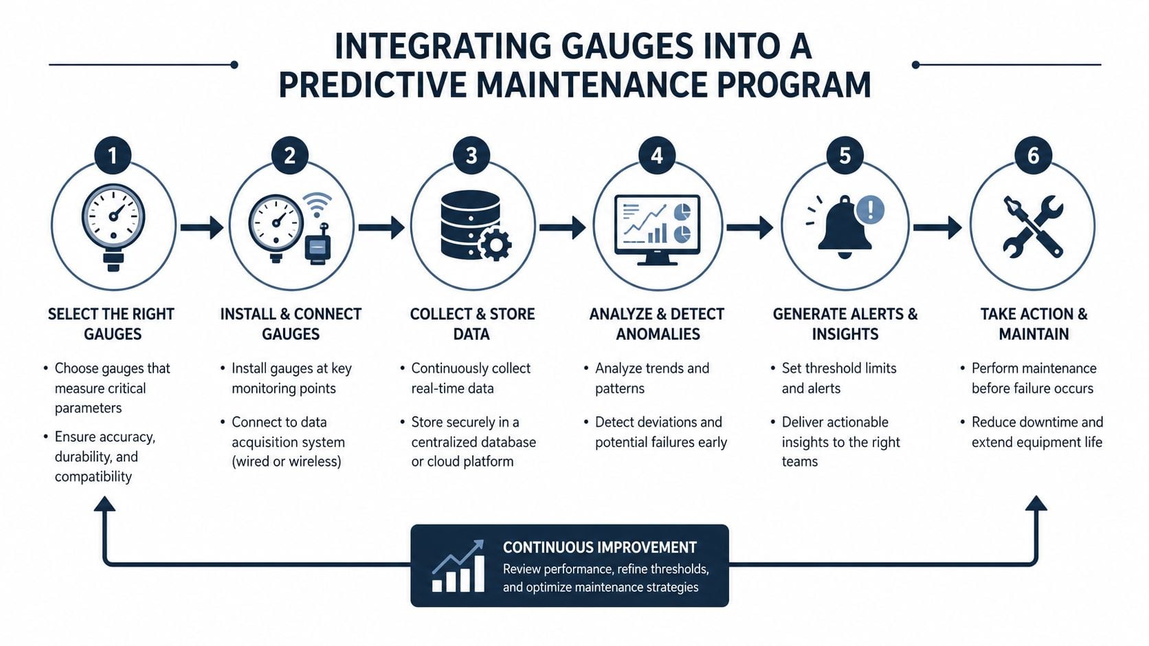
Magnetic level gauges belong in a predictive maintenance program when inspection tasks, proof tests, and condition triggers are defined in the asset system. Their maintenance logic should connect local movement, independent process data, corrosion findings, and response time to the consequence of failure.
Assign the right proof-test interval
Set the interval by consequence and safety function. A gauge used for non-SIL indication may follow a broader periodic functional test. If it contributes to a safety instrumented function, establish the proof-test interval through the safety lifecycle, demand analysis, and required risk reduction. Document the basis instead of copying an interval from a generic instrument list.
Challenge the complete measurement path during a proof test:
- Float movement through the operating range.
- Local flag or follower response.
- Transmitter output, if installed.
- Alarm and trip behavior.
- Failure-state handling.
- Isolation-valve position and bypass status.
The stroke test and corrosion inspection may need different schedules. In corrosive service, set wall-thickness inspection intervals from the measured corrosion rate, service chemistry, and consequence of chamber loss. Refurbishment is reasonable when the chamber, connections, and indicator remain fit for service and the float or seals are the limiting parts. Replace the assembly when corrosion margin, material compatibility, or design history cannot be demonstrated.
Add simple condition-monitoring triggers
Use operator rounds to check flag readability, sticking, external leakage, coating damage, chamber temperature, and agreement with the control-system trend. Record the observation with the asset number and process condition so repeated findings can be trended. A discrepancy should create a work request, not a manual reset of the indicator.
A transmitter with defined fault signaling can support this workflow. Magnetic level gauge documentation describes NAMUR NE43-style behavior, including a low failure current of 3.6 mA and a high failure current of 21 mA, when the device cannot determine a plausible float position in the operating documentation. Configure the control system to distinguish those states from a genuine process value, then verify the configuration during commissioning and periodic proof testing.
Put the gauge in the asset system
List the instrument on the P&ID, equipment register, inspection plan, and CMMS task list. A useful record includes:
- Service fluid and density range.
- Chamber and float material.
- Pressure and temperature design limits.
- Safety-function or operator-only classification.
- Last stroke test and proof test.
- Wall-thickness readings where corrosion is credible.
- Open defects, bypasses, and isolation issues.
Use condition monitoring systems to organize route findings, process comparisons, and escalation rules. A condition trigger should initiate a work order when local indication and the independent process signal diverge beyond the site's approved tolerance over a defined observation window. Set that tolerance from instrument accuracy, process dynamics, and consequence analysis, rather than applying one universal number.
A Real-World Example and Your Next Step
A produced-water treatment train used a separator vessel with a 6 m chamber, 11 bar pressure, and 65°C operating temperature. Light hydrocarbon carryover complicated the service, while fluid density fluctuated between 0.92 and 1.05 g/cm³. The measurement needed to remain useful during changing composition, not just under a stable commissioning condition.
The specification used a non-metallic float, a PTFE-lined chamber, and a reed-chain transmitter. The non-metallic float reduced susceptibility to process-related magnetic debris, while the lining addressed the chemical exposure identified in the service review. The transmitter provided a control-system signal, but the plant still treated mechanical float movement as the primary measurement-path dependency.
Commissioning and routine verification
The installation team confirmed chamber verticality at under 1°, verified density against a calibrated grab sample, and followed the approved isolation-valve sequence before opening the chamber. The proof test moved the float through the available range and compared the local indication and transmitter signal with the independent reference.
During monthly operator rounds, the team performed a controlled stroke check and looked for sluggish flag response. A quarterly proof test compared the gauge against the sight glass baseline. After nine months, magnetic debris fouled the float and the gauge began to drift by 3%. The routine comparison caught the discrepancy before it became a level trip.
The response focused on the cause, not only the symptom. Maintenance removed and cleaned the float, inspected the chamber and connections, checked for additional ferrous contamination, and reviewed whether a magnetic trap and improved upstream cleanliness control were required. The condition was then recorded in the CMMS asset-management process so future inspection tasks remained visible.
This example shows why service severity should determine inspection effort. A clean tank with stable density may need a different route frequency from a produced-water separator with carryover, debris, and changing fluid properties. A gauge tied to a protective function also needs a formal proof-test plan, independent verification, and controlled bypass management.
Reliability engineers and maintenance managers should review every installed gauge against four questions: Does the float match the actual density range? Can corrosion or fouling immobilize it? Is there an independent way to challenge the indication? Does the CMMS contain a task that will detect silent drift before the process exposes the weakness?
Forge Reliability provides predictive maintenance, condition monitoring, reliability consulting, and asset-management support for industrial facilities that need fewer unplanned failures. Request a free reliability assessment through Forge Reliability to review magnetic level gauge selection, proof-testing, condition-monitoring triggers, inspection intervals, and CMMS coverage across the plant.