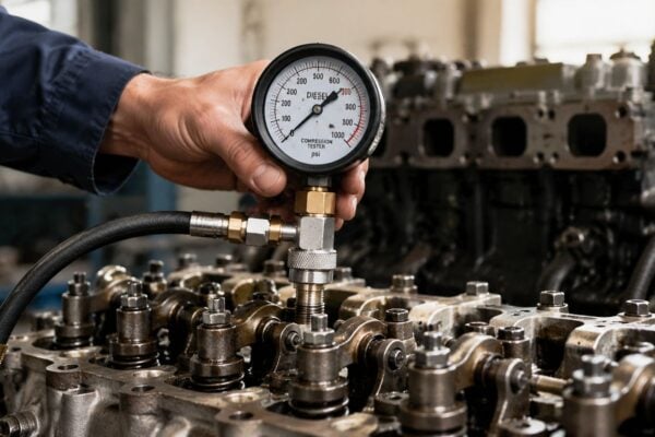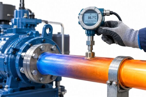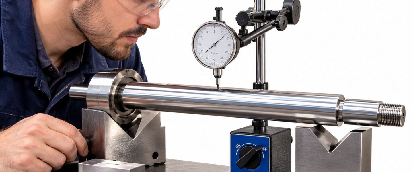
A centrifugal pump on a chemical line keeps damaging its mechanical seal, or a motor coupling cracks again soon after alignment. The crew may already have checked soft foot, shimmed the motor, and verified the coupling with a laser. Yet the recurring failure remains because the shaft itself, the coupling fit, the bearing support, or the measurement setup may be moving during rotation.
Shaft runout measurement helps expose that hidden condition before alignment work turns into repeated rework. The result is reported as Total Indicator Reading, or TIR, the difference between the highest and lowest indicator readings during one slow revolution. ASME/ANSI B5.54-2005 defines runout as the total indicator reading from an instrument measuring against a moving surface, making the term relevant to rotating equipment and broader metrology practice. The practical field method is simple, but the measurement system must be controlled with care.
Table of Contents
- Why Shaft Runout Measurement Matters on the Plant Floor
- Understanding Runout Types and Choosing the Right Instrument
- Preparing the Shaft and Fixturing for a Clean Reading
- Measuring Radial, Axial, and Total Runout Step by Step
- Reading the Numbers and Applying the Right Tolerances
- Separating True Shaft Defects from Measurement Errors
- Turning Runout Data into Maintenance Decisions and Action
Why Shaft Runout Measurement Matters on the Plant Floor
A pump shaft that is bent between bearings can force a mechanical seal to open and close as the shaft rotates. A journal that no longer runs concentrically can load a coupling unevenly. Bearing housings that permit axial float can make a stable shaft appear to have face runout. These conditions produce familiar symptoms, including seal wear, vibration, coupling fatigue, and premature bearing distress.
A dial indicator can reveal the pattern before a laser alignment tool is powered up. If the reading rises and falls consistently at a bearing journal, coupling fit, and seal sleeve, the crew has evidence of a geometry problem rather than just an alignment offset. If the high point changes after the setup is disturbed, the team may be measuring fixture movement, debris, or axial motion instead of shaft eccentricity.
Practical rule: Alignment corrects the relationship between machine centerlines. It can't correct a shaft or coupling that doesn't rotate around the intended centerline.
What the first pass should reveal
Runout should be checked at several axial planes, not just one convenient spot. A useful profile includes:
- Inboard bearing journal: Shows how the shaft runs near the support.
- Midpoint between bearings: Helps identify bow or shaft deflection.
- Coupling fit: Separates coupling installation problems from shaft geometry.
- Seal sleeve or seal area: Connects the reading to recurring seal failure.
- Free end: Helps establish whether the deviation is local or distributed.
A manufacturer's published motor table lists permissible shaft runout at 0.002 inches, with face runout at 0.004 inches and rabbet diameter tolerance of +0.003/-0.000 inches across a broad frame range. Those values are small enough that a burr, loose bracket, or angled probe can change the maintenance decision. The published measurement guidance also supports checking runout across the shaft rather than treating one location as representative. The manufacturer's shaft runout measurement guidance provides the relevant practical context.
Why reliability teams should trend it
Runout belongs in overhaul, coupling replacement, and recurring-failure investigations. It also belongs beside vibration and lubrication data in the asset history, because a shaft condition can explain why vibration returns after alignment or why seals fail despite apparently acceptable operating conditions.
The first question isn't “Is the shaft bad?” It's “Can the measurement be trusted?” Bracket flex, cosine error from an angled indicator stem, axial float, sag, and dirty contact surfaces must be controlled before a TIR value becomes a work order. Teams building a broader industrial reliability program can also review this growth agency with ContentBuck resource when developing technical communication for manufacturing audiences.
Understanding Runout Types and Choosing the Right Instrument
Runout has different forms, and each one answers a different maintenance question. Radial runout measures variation on a cylindrical surface as the indicator contacts it perpendicular to the shaft axis. Axial or face runout measures variation on a face, thrust collar, or coupling surface as the shaft completes a revolution. Total runout evaluates variation across a defined length or surface, so it can expose both local surface variation and a broader shaft bend.
The instrument should match the question, the environment, and the required repeatability. A field crew often starts with a dial indicator, while internal fits and running machinery may require different methods.
Instrument selection in practice
A 0.001-inch dial indicator or 0.01 mm dial indicator on a magnetic base is the practical workhorse for motor shafts, pump rotors, coupling fits, and shop inspection. It's affordable, visible to the technician, and effective when the base is rigid and the probe is correctly oriented. The limitation is that it measures contact movement, so fixture deflection, surface debris, thermal movement, and operator technique can enter the result.
A bore gauge with a coaxial probe suits internal diameters and tight fits where an external indicator can't reach the relevant surface. It can help assess an internal coupling bore or housing feature, but it demands controlled contact, correct zeroing, and disciplined calibration.
A non-contact eddy-current or laser displacement sensor avoids probe contact and can support high-speed, hot-running, or continuously monitored equipment. These systems are useful for trending, but they require careful installation, target-surface preparation, signal validation, and calibration. A sensor that sees thermal growth or target reflectivity changes may report movement that isn't shaft geometry.
| Instrument | Typical Resolution | Best Use Case | Key Limitation |
|---|---|---|---|
| Dial indicator on rigid base | 0.001 in or 0.01 mm | Field and shop checks on journals, sleeves, and coupling fits | Contact force and fixture movement can distort readings |
| Bore gauge with coaxial probe | Application-dependent | Internal bores and close-fit inspection | Requires controlled access, zeroing, and calibration |
| Non-contact displacement sensor | Application-dependent | High-speed, hot-running, or trending applications | Installation, target condition, and signal validation affect confidence |
Resolution isn't the same as accuracy. Before measurement, the crew should verify the indicator or sensor against a known reference, confirm the return to zero, and record the instrument identification. A useful related reference for connecting mechanical measurements with broader condition monitoring is this guide to how to measure vibrations.
Preparing the Shaft and Fixturing for a Clean Reading
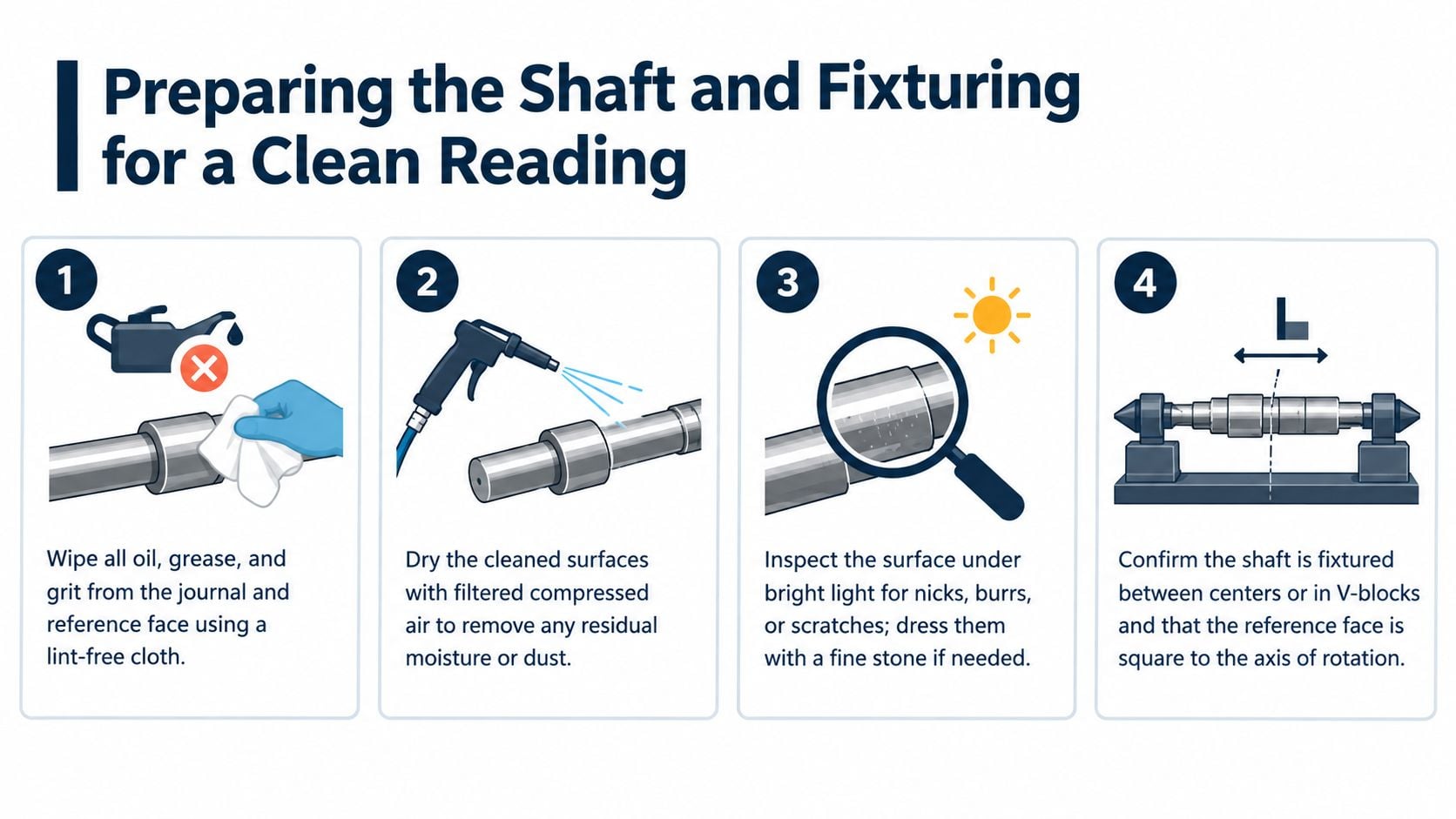
Preparation determines whether the dial tracks the shaft or the contamination around it. Oil, grease, grit, rust scale, and a small burr can create a false high point. The technician should wipe the journal and reference face with a lint-free cloth, dry the surfaces with filtered compressed air, and inspect them under bright light before mounting the indicator.
The shaft's support must represent the question being asked. A shaft installed in its own bearings gives the most realistic installed geometry because it includes bearing clearances, housing relationships, and support conditions. V-blocks on a clean surface plate provide a controlled datum for an unmounted shaft. Between centers on a lathe or bench center offers a stiff reference for a bare shaft, but it won't show how a flexible or damaged housing affects the installed rotor.
Match the fixture to the decision
For a centrifugal pump suspected of seal damage, measurement in the pump's own bearings is usually the relevant baseline. If the shaft is removed for repair, between-centers measurement can separate shaft geometry from housing influence. Both results can be valid, but they answer different questions.
The indicator base must sit on a clean, flat, rigid surface. A magnetic base that is attached to a thin guard, vibrating cover, or contaminated mounting pad may flex while the shaft remains stable. The probe tip should contact the measured surface perpendicular to the radial direction. For a face measurement, the probe arrangement must follow the face variation without allowing the stand to twist.
A pre-rotation inspection
Before turning the shaft, the technician should check that:
- The shaft is clean: No oil film, grit, rust scale, burr, or loose coating remains at the contact area.
- The base is rigid: The magnetic base or stand is locked to a stationary, structurally sound surface.
- The contact is correct: The probe is oriented for the intended radial or axial measurement.
- The shaft is supported correctly: Bearings, V-blocks, or centers match the measurement objective.
- The reference face is suitable: The face is square enough for the intended axial runout check.
A precision alignment program may need a different fixture and verification sequence from a basic field check. The principles described in precision shaft alignment services apply when runout data must support a larger alignment decision.
Measuring Radial, Axial, and Total Runout Step by Step
A reliable sequence starts before the shaft moves. The technician should inspect the indicator, verify it against a calibration block or slip gauge, and confirm that the pointer returns to zero across the known reference. The instrument serial number and calibration status belong in the measurement record, especially when the result may determine teardown or acceptance.
Mark a starting position on the shaft with a paint pen. Mount the indicator on a magnetic base or rigid stand, preload it lightly, and set the pointer to zero at the mark. The probe must be perpendicular to the shaft surface for radial runout. The shaft should then be rotated slowly by hand through one complete 360-degree revolution while the technician records the maximum and minimum readings.
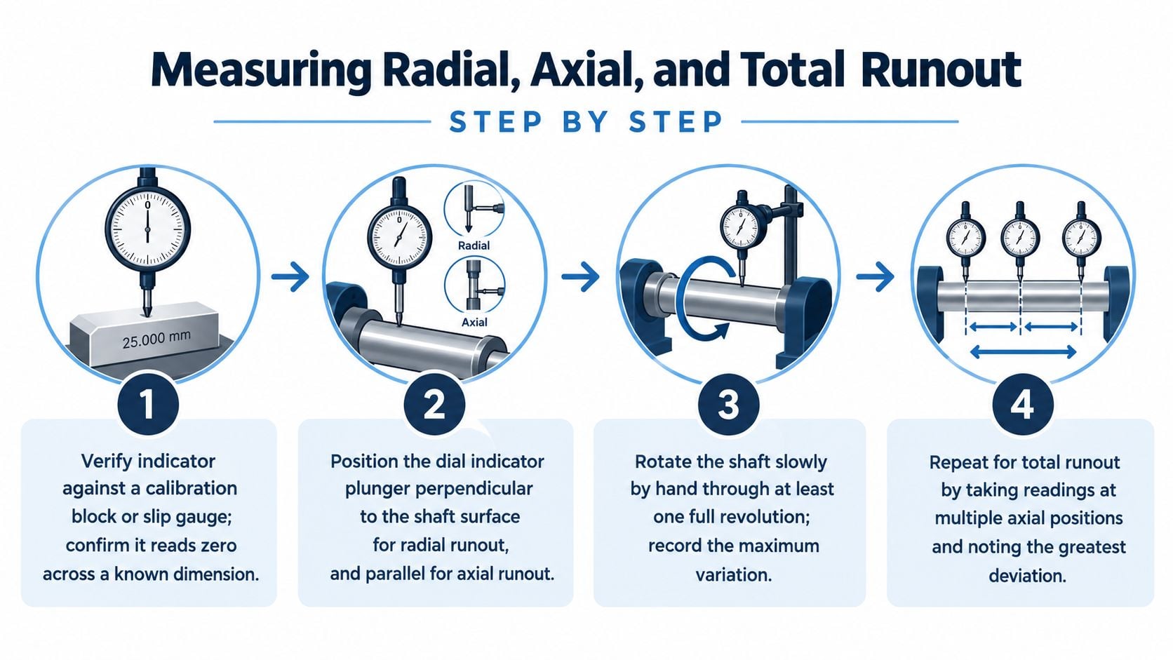
Radial runout sequence
At each axial plane, the technician should record the high and low points rather than relying on a visual impression. TIR is calculated as:
TIR = maximum indicator reading minus minimum indicator reading
For example, a pump shaft may be checked at the inboard bearing journal, midpoint, coupling fit, and seal sleeve. The reading at each location becomes its own data point. The crew shouldn't average these readings, because averaging can hide a local high spot at the seal area.
The maximum angular position should be marked. If the high point at the coupling fit aligns with the high point at the seal sleeve, the pattern may indicate a consistent shaft or assembly relationship. If the high point changes sharply between planes, the profile may indicate localized surface damage, a coupling bore issue, or a bent shaft.
Axial or face runout sequence
For axial runout, reposition the indicator against the shaft end face, thrust collar, or coupling face. The probe should track the face variation as the shaft turns through the full revolution. Record the highest and lowest readings and calculate the face TIR from those extremes.
Face runout matters when a coupling face, thrust surface, or seal-related reference surface must remain square to the axis. A face can produce an alignment symptom even when a radial journal appears acceptable.
Total runout profile
Total runout requires readings at multiple axial positions across the defined surface or shaft length. Each plane should have a recorded TIR value, an angular high-point position, the fixture arrangement, and the shaft temperature. The greatest deviation shouldn't replace the profile. It should be interpreted within it.
Slow hand rotation is essential. Dynamic rotation can introduce vibration and inertia, while fast manual movement can cause the operator to miss the true maximum and minimum. Teams that pair this work with a broader vibration analysis sensor program can compare the static geometry profile with operating vibration behavior.
Reading the Numbers and Applying the Right Tolerances
TIR isn't a universal pass or fail number. The appropriate limit depends on shaft diameter, speed, machine design, bearing span, seal type, coupling construction, and the consequence of failure. A general machinery reference commonly uses TIR less than or equal to 50 micrometres, or 0.002 inches, or D/2000, whichever is greater, with speed-based reductions applied above 1800 rpm. The cited guidance reduces the allowable value to 75% between 1800 and 3600 rpm, 50% between 3600 and 7200 rpm, and 25% above 7200 rpm. This technical explanation of shaft runout measurement describes that speed-sensitive approach.
A separate motor guideline uses five percent of the average radial air gap or 0.003 inches, whichever is smaller, for motor shaft runout. The air-gap relationship matters because shaft eccentricity can alter magnetic clearance, increase vibration, and increase bearing or seal loading. The motor shaft runout tolerance guide provides that application-specific reference.
Use the profile, not a single number
A motor shaft can show a local coupling-fit problem while the bearing journals remain stable. A centrifugal pump can show modest journal TIR but unacceptable movement at the seal sleeve. A high-speed spindle requires a more conservative interpretation than a slower general-purpose shaft.
| Equipment Class | Speed Range (RPM) | Radial at Bearing Journal | Radial at Seal/Sleeve | Axial at Coupling Face | Total Runout |
|---|---|---|---|---|---|
| General motor | 1800 and below | Use OEM or machine-specific limit | Use seal manufacturer or OEM limit | Use coupling specification | Use documented assembly limit |
| General motor | Above 1800 to 3600 | Apply speed-sensitive reduction | Tighten where seal loading is critical | Confirm coupling face condition | Review profile and vibration |
| High-speed motor or pump | Above 3600 | Use tighter machine-specific limit | Treat seal-area deviation as high risk | Confirm face squareness | Escalate against OEM criteria |
| Fan or low-consequence rotor | Application-dependent | Use equipment specification | Usually not applicable | Check hub or coupling interface | Trend against baseline |
| Machine tool spindle | Application-dependent | Use drawing or spindle specification | Application-dependent | Use tool-interface requirement | Require precision metrology review |
For size-based work, a published tolerance table gives 0.030 mm normal and 0.015 mm reduced tolerance for shafts up to 10 mm, while 50 to 80 mm shafts receive 0.060 mm normal and 0.030 mm precision tolerance. Those values demonstrate why one absolute limit cannot serve a small packaging spindle and a large pump rotor alike. This runout tolerance reference provides the size-based comparison.
Observed indication includes setup noise. True geometric runout is more defensible when the shaft is rotated between centers or measured in a controlled datum arrangement, then compared with the installed-bearing result. Reliability teams can use ISO vibration standards guidance to place the mechanical reading alongside operating vibration criteria, but the equipment specification remains the governing acceptance document.
Separating True Shaft Defects from Measurement Errors
A high dial reading doesn't prove that the shaft is bent. The technician first has to challenge the measurement system. A probe that isn't perpendicular creates cosine error, while a flexible bracket can make the indicator follow stand movement. Axial float can move the shaft along its own axis and contaminate both radial and face readings.
Cosine error is associated with an angled probe and changes the measured component of movement. The practical correction is not to calculate a theoretical adjustment in the field. It's to reposition the probe so its measurement axis is correct, preload it lightly, and repeat the sweep.
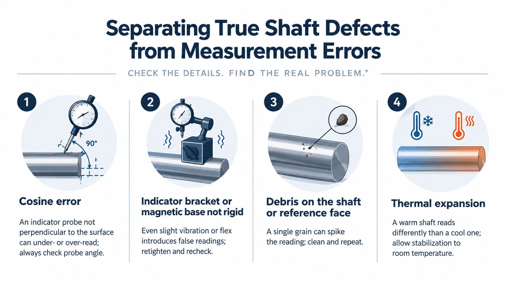
A fast diagnostic decision tree
- Does the needle return to the starting value after 360 degrees? If not, check axial float, a loose setup, indicator drift, or a support that moved.
- Does the reading repeat after the base is repositioned? If the high point or waveform changes, suspect bracket flex or magnetic-base movement.
- Does cleaning change the high point? If it does, inspect for burrs, grit, rust scale, or a damaged contact surface.
- Does probe orientation change the result? If it does, correct the contact angle before judging the shaft.
- Does the pattern remain across several axial planes? A repeatable pattern supports a true geometry issue, while an isolated spike suggests local surface or setup error.
- Does the installed reading differ from the between-centers reading? Investigate bearing clearance, housing condition, sag, and support geometry before authorizing machining.
A repeatable measurement is evidence. A large measurement that cannot be repeated is only a troubleshooting clue.
Horizontal shafts can sag when supported incorrectly. V-blocks that don't sit under the correct journals can introduce their own geometry. Bearing axial float should be controlled by applying a defined axial thrust appropriate to the machine and procedure, not by forcing the shaft against an unknown stop.
For recurring coupling failures, the team should also inspect the hub bore, fit, face, and installation method. A shaft may be straight while a coupling hub is eccentric or skewed. Guidance on shaft misalignment can help frame the subsequent alignment investigation, but the runout setup still has to prove whether the shaft or the assembly is moving.
Turning Runout Data into Maintenance Decisions and Action
A TIR value becomes useful when it leads to a controlled decision. The response may involve cleaning and repeating the measurement, inspecting bearings, correcting a coupling fit, re-machining a journal, straightening a shaft, balancing the rotor, or realigning the machine. The right action depends on the location and repeatability of the deviation, not only its magnitude.
Practical field guidance often places general machinery near 0.002 inches TIR, with 0.001 inches suggested for higher-speed machines above 3600 rpm. This rotating-equipment runout guidance explains why high-speed compressors and sealed pumps may require tighter control. Another application reference cites 0.001 inch TIR maximum for vertical turbine pump shafts, showing why equipment-specific documents must govern the final decision. The vertical turbine pump reference provides that application context.
Convert readings into work orders
| TIR Reading (µm) | Condition | Recommended Action | Priority |
|---|---|---|---|
| Under 25 | Typically suitable for monitoring when the profile is stable and the machine specification permits it | Record baseline, correlate with vibration, and repeat at planned intervals | Routine |
| 25 to 75 | Corrective work may be justified, depending on speed, location, and equipment criticality | Schedule machining, coupling inspection, bearing inspection, or alignment correction | Planned |
| Above 75 on a 75 mm shaft | Potentially unacceptable for a critical rotating assembly | Stop and validate the setup, then consider immediate teardown if confirmed | High |
These bands are decision aids, not replacements for the OEM limit. A reading at the seal sleeve deserves more attention than the same reading at a nonfunctional free-end surface. A repeatable high point across several planes supports escalation, while a reading that disappears after cleaning or fixture correction supports remeasurement.
Build a defensible record
The report should include:
- Equipment ID and location: Pump, motor, compressor, or other asset reference.
- Instrument serial and calibration date: Establishes measurement traceability.
- Fixture arrangement: In-own-bearings, V-blocks, or between centers.
- FIM and PIR readings: Face indicator movement and radial indicator movement, with axial plane identified.
- Temperature and ambient conditions: Helps explain changes between measurements.
- Angular high-point marks: Supports comparison during future inspections.
- Technician sign-off and trend notes: Captures repeatability, anomalies, and follow-up actions.
Store the report in the CMMS beside vibration, lubrication, alignment, and failure-history data. That time series helps planners tune predictive-maintenance intervals and distinguish a developing shaft problem from a one-time installation error. Teams expanding their maintenance strategy can use this guida alla manutenzione predittiva industriale as additional program context.
Forge Reliability provides predictive maintenance, condition monitoring, and reliability consulting that can include runout checks, vibration analysis, alignment review, and CMMS-linked asset decisions. A free reliability assessment can help a plant validate its measurement practices before it approves unnecessary teardown or accepts a defect that may damage seals and bearings.
Forge Reliability can assess a plant's shaft runout procedure, fixturing, calibration records, and connection to vibration and lubrication data. Visit Forge Reliability to request a free reliability assessment and standardize runout checks during major overhauls and coupling alignment visits.