At 2 a.m. on a chemical dosing skid, the flow number looks fine at startup, then the density trace begins to wander, the totalizer creeps, and the operator starts asking the question nobody likes on a live unit, what changed? The meter is still bolted in place, the transmitter still powers up, and the loop still responds, which is exactly why these problems get missed until they become shift-end disputes, off-spec dosing, or a maintenance call that burns time on a guess.
A flow transmitter Micro Motion should be treated as a long-term asset, not a one-time commissioning checkbox. In the field, the failure usually isn't dramatic on day one, it shows up months later as noise, drift, nuisance alerts, or a reading that is technically alive but no longer trustworthy.
Table of Contents
- When a Micro Motion Transmitter Starts Lying to You
- Reading the Specification Sheet Like a Reliability Engineer
- Installation Choices That Decide Your Next Three Years of Maintenance
- Failure Modes and the Diagnostic Signatures They Leave Behind
- Matching the Transmitter to the Industry Application
- Calibration and Maintenance Workflow That Holds Up in an Audit
- Wiring the Transmitter Into Your Condition Monitoring Strategy
- Troubleshooting Decision Tree and Next Steps
When a Micro Motion Transmitter Starts Lying to You
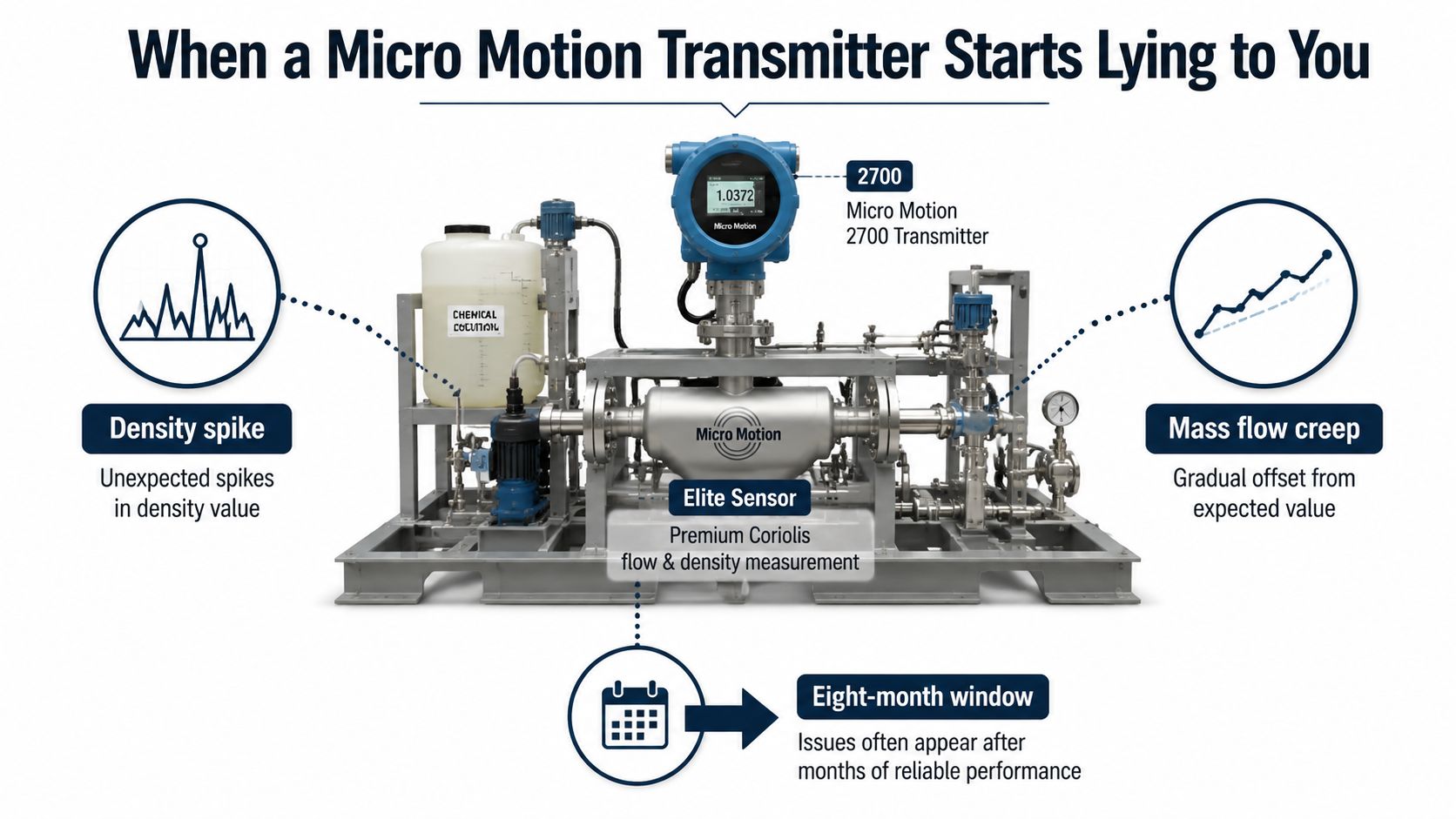
A reliable transmitter can go bad in a way that feels almost insulting. On a dosing skid in a chemical plant, the first eight months often look boring, then density starts spiking for no obvious reason, the mass flow trace creeps away from the expected value, and the totalizer no longer matches the batch record. The instrument isn't always failing in a catastrophic sense, it's often telling the truth badly enough to create real operational pain.
A Coriolis meter doesn't infer flow the way a volumetric meter does. It measures mass flow directly by watching how vibrating tubes twist under moving fluid, a bit like a skater pulling her arms in to spin faster and extending them to slow down. That twisting, plus the vibration behavior of the tubes, gives the transmitter the raw information needed to report mass flow, density, and temperature from the same sensing element.
Why the reading changes after commissioning
That simple physics is exactly why these meters reward long-term attention. If the process changes, the ground path degrades, a cable gets damaged, or the sensor starts seeing aeration, the transmitter may still produce a number that looks reasonable at first glance while drifting away from reality. For recurring field faults, the better question isn't whether the meter “works,” it's whether it still tracks the process under operating conditions.
Micro Motion sensors are built in different geometries, including U-tube and straight-tube designs. Dual-tube systems dominate high-accuracy applications because the opposing tube motion helps stabilize the measurement and makes the signal easier to interpret when conditions are clean and the installation is sound. In practice, that also means a good installation can stay quiet for a long time, while a marginal one can look perfect at startup and then become noisy only after thermal cycling, vibration, or process upsets start stacking up.
Practical rule: if a transmitter drifts only after it has been in service, the root cause is often outside the electronics box. Check the process, the cable, the grounding, and the mounting before assuming the sensor has failed.
For a structured approach to recurring faults, many reliability teams use root-cause discipline instead of swapping parts blindly, and a good starting point is root cause failure analysis. That mindset matters because a meter that looks fine on the bench can still fail in the plant for reasons the bench never exposes.
The useful mental model is simple. The sensor is the vibrating measurement element, the flowtube is the part the process touches, the transmitter conditions the signal and runs diagnostics, and drive gain is one of the clues that tells maintenance whether the system is working harder than it should. Once those terms are clear, the meter stops feeling magical and starts behaving like any other asset with failure modes, symptoms, and a repair path.
Reading the Specification Sheet Like a Reliability Engineer
A Micro Motion datasheet is a maintenance document if the plant depends on it. Read the numbers as operating boundaries, not as sales language. The F-Series spans from 100 lb/min (2,720 kg/h) on the F025 to 10,000 lb/min (272,000 kg/h) on the F300, which shows the platform can cover low-flow batching and large-process throughput without changing the basic maintenance logic F-Series product data.
The numbers that drive maintenance decisions
Accuracy matters, but it does not tell the whole story. Emerson's technical overview lists liquid mass-flow accuracy as good as ±0.05% on Elite and F-Series sensors, with mass-flow repeatability of ±0.025% on Elite and ±0.05% on F-Series, while gas-density measurement options can be ±0.1% or ±0.15% of density reading Emerson transmitter and sensor overview. Those figures matter because repeatability is what keeps a loop steady shift after shift, and density accuracy is what lets the meter support quality and concentration decisions without adding another instrument.
A reliability engineer should read zero stability next. On the F-Series, Emerson lists zero-stability values as low as 0.0065 lb/min (0.1765 kg/h) on the F025 and 0.80 lb/min (21.76 kg/h) on the F300 F-Series product data. That matters in low-flow service, because a meter can look strong on paper and still create visible offset error when the process spends much of its time near the bottom of range.
| Specification | Typical Micro Motion Value | What It Means for Reliability |
|---|---|---|
| Maximum flow capacity | 100 lb/min to 10,000 lb/min F-Series product data | Confirms whether the meter is sized for batch, utility, or throughput service |
| Liquid mass-flow accuracy | ±0.05% on Elite and F-Series Emerson transmitter and sensor overview | Supports tight control where small errors become product loss |
| Mass-flow repeatability | ±0.025% on Elite, ±0.05% on F-Series Emerson transmitter and sensor overview | Tells you how stable the signal should look from run to run |
| Gas-density accuracy | ±0.1% or ±0.15% Emerson transmitter and sensor overview | Useful for quality and concentration monitoring |
| Zero stability | As low as 0.0065 lb/min on F025 F-Series product data | Sets the floor for low-flow offset and giveaway risk |
That same mindset helps when comparing instrumentation reliability against asset-life concepts like what does MTTF mean. A meter can have strong repeatability and still become a maintenance burden if installation and zero behavior force repeated field intervention.
The spec sheet should answer one question first, can this meter stay inside tolerance where the process runs, not where the range starts.
For planning, the best internal question is simple, what is the acceptable totalizer drift per shift, and does the zero stability support it? If the application is a low-flow injection skid, a batching line, or a custody-transfer loop, the right meter is the one whose weakest spec still fits the operating window. For teams that want to separate a stable asset from one that only looks good while it is new, Weibull analysis software can help turn spec reading into a longer-term maintenance view.
Installation Choices That Decide Your Next Three Years of Maintenance
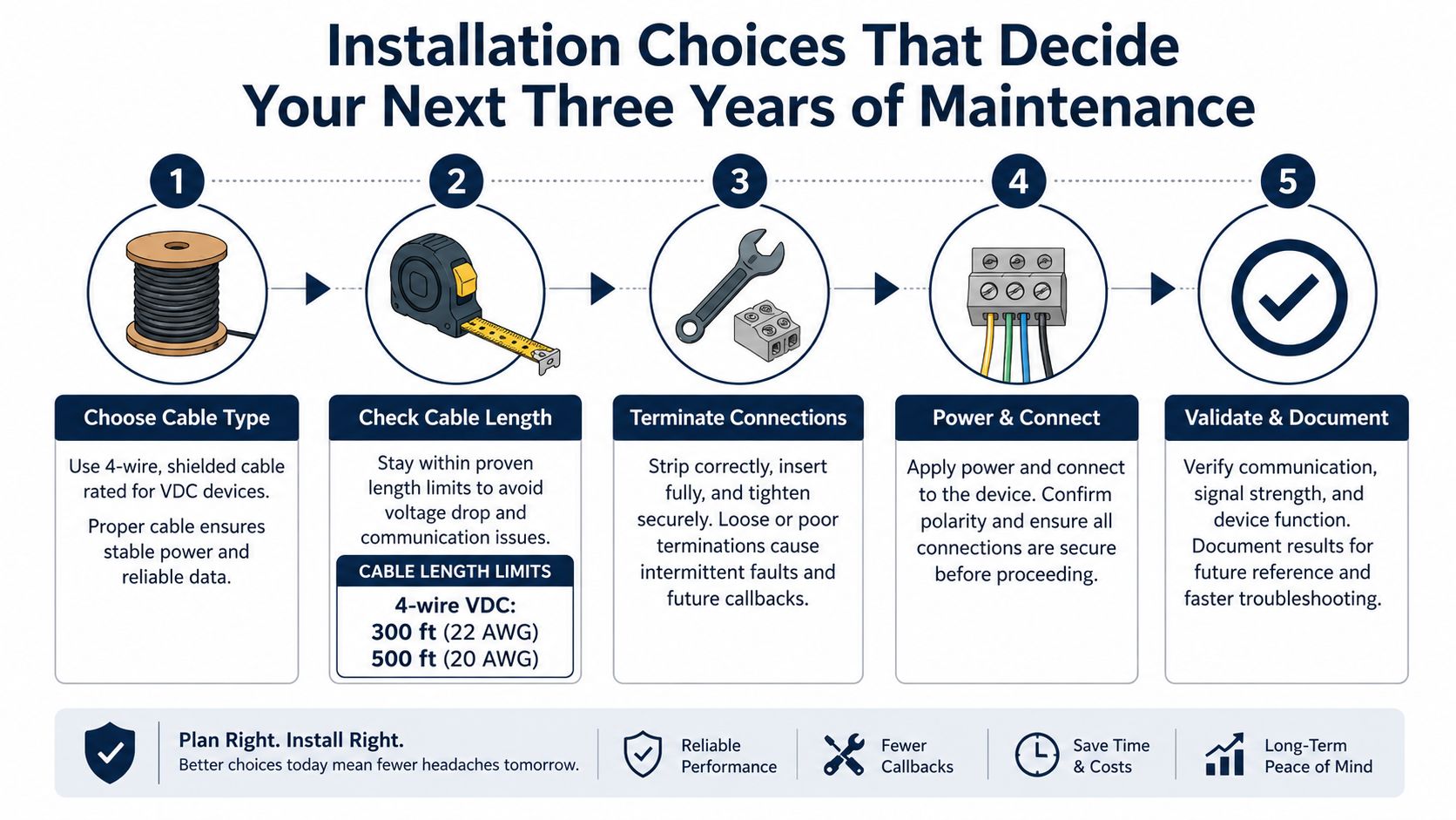
A quiet Micro Motion installation starts with disciplined basics. Cable length, grounding, transmitter placement, and enclosure rating decide whether the meter stays stable in service or turns into a repeat callout after the first weather swing or maintenance shutdown. The hardware can be right on paper, yet poor installation still creates voltage-drop issues, comms instability, and nuisance diagnostics.
Cable length is not a minor detail
Emerson specifies strict cable-length limits. For 4-wire VDC cable, the limits are 300 ft (91 m) at 22 AWG, 500 ft (152 m) at 20 AWG, and 1,000 ft (305 m) at 18 AWG, while RS-485 can run 1,000 ft (305 m) with 22 AWG or larger Micro Motion Elite documentation. A remote-mounted transmitter on a tank farm or utility corridor can look fine at startup, then begin showing communication dropouts or signal degradation after thermal cycling, repair work, or conductor aging.
The transmitter housing is rated NEMA 4X (IP66) on the ELITE platform, which makes it suited to washdown and corrosive environments ELITE platform datasheet. On a food and beverage skid or in a wastewater chemical room, that rating is part of the reliability case, because moisture and ingress are common causes of intermittent faults.
Architecture drives the trade-off. A Micro Motion 4200 2-wire transmitter can report mass flow, volume flow, gas standard volume flow, temperature, or density through a single passive 4–20 mA output with HART, with a 600 Ω maximum load and 17.8 to 30 VDC external power 4200 2-wire transmitter data sheet. That fits a chemical dosing skid or a remote tank-farm meter where simple wiring matters more than extra options.
The ELITE platform supports up to five fully configurable I/O channels and communication options including 2-wire, Ethernet, and wireless, which makes sense where one device has to feed control, diagnostics, and asset-health systems without extra instrumentation ELITE platform datasheet. On a custody-transfer skid, that flexibility can matter more than a cleaner cable tray.
Grounding and termination deserve the same attention as cable selection. A long run can behave well in the shop and fail in the field if shield bonding is inconsistent, and remote installations need the same discipline used on other low-level process loops, including setups that depend on stable 4 to 20 mA behavior such as a dissolved oxygen sensor installation.
For water and wastewater service, a practical reference point is water and wastewater reliability planning, where harsh environments and remote runs create the same maintenance patterns seen in process plants.
Field habit that pays off: if the transmitter is remote-mounted, verify cable gauge, termination quality, and grounding before energizing. That one check prevents many of the problems that only show up after the unit has been in service for months.
What to validate before handing the asset over
- Cable gauge and distance: confirm the run fits the published limit, not the drawing estimate.
- Grounding path: make sure the meter and shield follow the intended bonding route.
- Mounting position: confirm the enclosure stays accessible and protected from washdown splash and vibration.
- Loop burden: on 2-wire loops, verify the load and power supply fit the transmitter requirements.
- Signal acceptance: check that mass flow, density, and diagnostics behave normally under real process conditions, not just during a dry checkout.
Failure Modes and the Diagnostic Signatures They Leave Behind
A Micro Motion transmitter rarely quits cleanly. It usually leaves a trail in the history file, the output trend, or the loop behavior long before anyone opens the enclosure. The crew that learns to read those clues spends less time swapping parts and more time fixing the root fault.
Common symptoms and what they usually point to
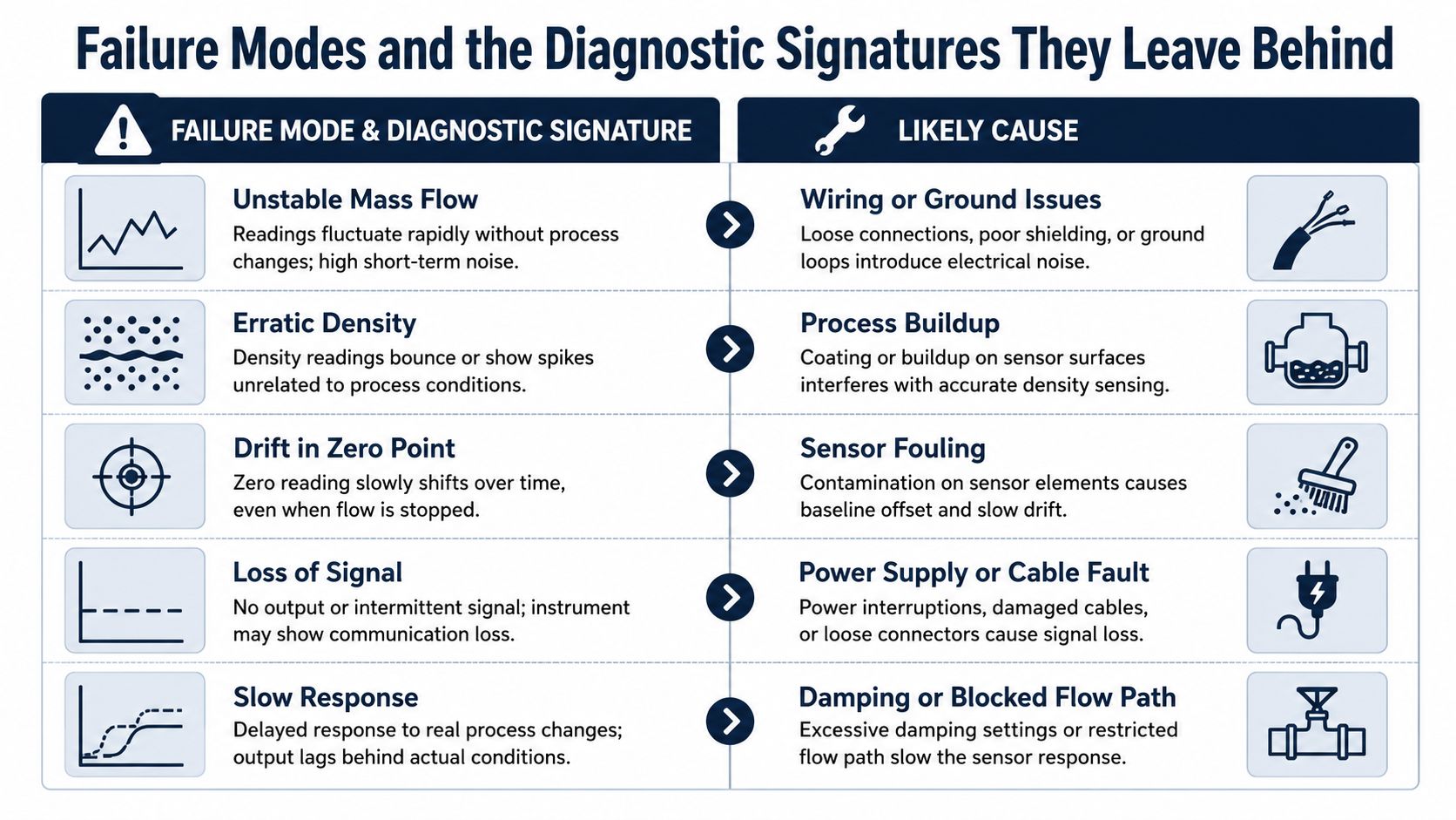
Unstable mass flow usually starts with wiring damage, grounding problems, or air in the line. Erratic density often points to process aeration, coating on the sensor tubes, or sensor damage. Zero drift over time is more likely to come from mechanical stress, poor mounting, or temperature effects on the installation. Temperature error usually traces back to RTD degradation, and communication dropouts often show up where cable damage, corroded terminations, or EMI from variable-frequency drives has gone uncorrected.
The best forensic tool is still the transmitter history. Time-stamped configuration changes, alerts, process events, and statistics give you a sequence that separates a bad sensor from a bad process move or a field wiring issue. In practice, that history matters most after the unit has been running for months, because the first signs of trouble are often small shifts, not obvious failures.
A simple troubleshooting matrix keeps the work honest.
| Symptom | Most likely direction | First field check |
|---|---|---|
| Unstable mass flow | Wiring, ground loop, or aeration | Inspect shielding, terminations, and process condition |
| Density spikes | Coating, two-phase flow, or tube damage | Review history files and inspect the process path |
| Zero drift | Mechanical stress or thermal influence | Verify mounting and re-zero under isolated conditions |
| Temperature error | RTD degradation | Compare against expected process temperature |
| Communication dropout | Cable or termination issue | Check run length, corrosion, and EMI exposure |
For remote runs, water and wastewater reliability planning often exposes the same weak points seen in process plants, especially on long cable paths and outdoor mounting points. The hardware may be fine while the installation slowly drifts out of spec.
Alert storms after a process upset need a different read. The transmitter may be doing exactly what it was configured to do, while the plant treats the alarm as proof the instrument has failed. History files settle that argument because they show whether the alerts began after a valve event, a cleaning cycle, a power disturbance, or a genuine process change.
Read the timeline before you read the alarm. The sequence usually tells the story faster than the symptom does.
That habit pays off in the field, and it also makes repair planning easier when the budget is tight. A unit with a recoverable wiring fault may only need a cable repair or termination cleanup, while a transmitter that keeps drifting after re-zero may be pointing toward a sensor problem or mounting issue that needs a heavier intervention. When replacement parts are scarce, even a maintenance repair overhaul 3D printing option can help shorten downtime if the rest of the loop is sound.
Matching the Transmitter to the Industry Application
A transmitter that behaves well on one skid can become a maintenance headache on another if the process duty changes. A food and beverage batching line needs stable outputs and clean traceability, a chemical dosing skid needs dependable low-flow continuity, and an oil and gas custody-transfer station needs repeatability that stands up when revenue and density correction are on the line. The hardware stays the same. The risk profile does not.
On a batching line, a Micro Motion 4200 2-wire transmitter is attractive because it can send mass flow, volume flow, gas standard volume flow, temperature, or density over a single 4–20 mA HART loop 4200 2-wire transmitter data sheet. That cuts wiring complexity and gives operators enough process visibility to catch ingredient variation without cluttering the skid with extra instrumentation.
Low-flow and custody-transfer are not the same job
On a chemical injection line, the LF-Series minimum flow capability of 0.002 to 59.5 lb/hr (0.001 to 27 kg/h) matters because valve leakage, line pulsation, and small process upsets can disappear into the noise floor on a meter that is not built for that range LF-Series datasheet. That turns low-flow stability into a maintenance issue as much as a process issue, because a small offset can shift totalized output enough to matter over time.
Custody-transfer service raises a different set of questions. Elite-class accuracy, density measurement, and repeatability support revenue and compliance work where the plant cannot afford a measurement dispute at the end of the month. A meter with steady density performance and repeatability is what lets the accounting side trust the process side.
The failure patterns also change by industry. In food and beverage, buildup and washdown exposure are often the practical enemies. In chemical processing, aeration and corrosion show up more often. In oil and gas, density drift and zero behavior draw the most attention because they affect the value of the stream itself. For water and wastewater plants, chemical dosing and utility metering often benefit from the same reliability habits used in water and wastewater asset planning, especially where long cable runs and outdoor mounting points slowly push the installation out of spec.
For plants that rely on field repair instead of full replacement, maintenance repair overhaul 3D printing can help with noncritical support parts. It does not change the need to diagnose the meter correctly before changing hardware. The transmitter may need a re-zero, a cable repair, or a sensor swap, and the application should decide which fix is worth the downtime and budget.
Calibration and Maintenance Workflow That Holds Up in an Audit
A transmitter passes audit review more easily when the crew uses the same maintenance path every time. On a Micro Motion system, that means a short, repeatable sequence with clean records, not a stack of loose notes and memory-based checks. The goal is simple. Show that the meter was inspected, verified, and returned to service under controlled conditions.
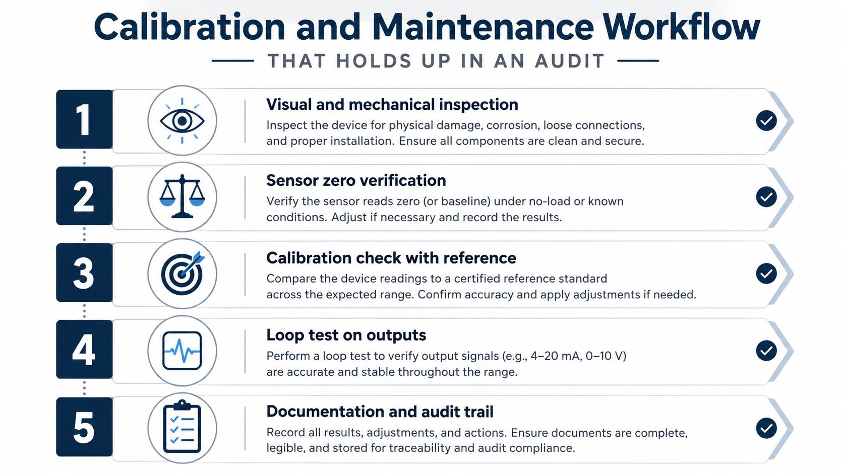
A practical sequence that survives scrutiny
Start with a visual and mechanical inspection, then isolate the process and verify sensor zero. After that, compare the reading against a reference meter or prover, run a loop test on the outputs, and record the results in the maintenance file. The transmitter history files carry a lot of weight during an audit because they preserve configuration changes, alerts, process events, and time-stamped statistics. That record is often what separates a clean review from a long argument about what happened in the field.
A criticality-based interval works better than calendar-only maintenance. Custody meters often justify tighter verification, batching skids usually fit a semi-annual rhythm, and low-criticality utility meters can often be checked annually if the process stays stable. The interval should follow risk, not habit.
Documentation discipline matters just as much as the mechanical work. A good SOP keeps the procedure from drifting when shifts change or a new technician inherits the job. A useful reference for teams trying to avoid doc rot in your SOPs is to keep the work order, the check steps, and the acceptance limits in one place, because a maintenance procedure that nobody can follow is the same as no procedure at all.
A compact checklist helps during the work:
- Inspect the housing and seals: look for moisture ingress, corrosion, and conduit damage.
- Confirm terminations: verify tight, clean connections at the transmitter and junction points.
- Check grounds and bonding: make sure the meter's grounding path matches the intended design.
- Review mounting and supports: confirm there is no strain, vibration problem, or misalignment.
- Document zero and verification results: keep the file with the meter record for audit traceability.
Factory recertification makes sense when long-term accuracy is in doubt or the meter is going back into critical service after a major process upset. In-situ work is the better call when the problem is clearly installation-related or the zero check shows the instrument is still healthy. If the maintenance system is tied to a CMMS asset management workflow, the technician can log the finding, attach the history file, and close the loop without extra paperwork.
Wiring the Transmitter Into Your Condition Monitoring Strategy
A Micro Motion transmitter should sit inside the reliability program, not beside it. Its diagnostics belong with vibration, oil analysis, thermography, and the other checks the plant already trusts, because transmitter health often shifts before product quality does. Set up that link early and the flow meter becomes an early warning asset instead of a passive display.
The integration path depends on the plant architecture. HART, Ethernet, and wireless outputs can feed a control system, a CMMS, and a condition monitoring platform at the same time when the wiring and data mapping are set up correctly. That matters in day-to-day work, because the operator, the planner, and the reliability engineer can all see the same transmitter history without separate trips to the field.
What to trend before trouble starts
The most useful variables are mass flow, density, temperature, drive gain, and tube frequency. Mass flow shows whether the process signal is stable, density shows whether the fluid behavior is changing, temperature helps separate process effects from equipment effects, and drive gain or tube frequency can show that the meter is working harder than normal. When those trends begin to move together, the asset deserves a closer look before it creates off-spec product or downtime.
The strongest programs tie transmitter health to asset criticality ranking. A meter protecting a high-value blend, a custody-transfer point, or a dosing line that affects compliance should get more attention than a noncritical utility loop. That makes the spending easier to defend because the plant can show why one meter gets trending, verification, and faster response while another stays on a longer interval.
A practical route is to place transmitter diagnostics beside vibration readings on pumps and thermography on MCCs. If the meter's density starts to oscillate while pump vibration stays normal, the likely issue may be tube coating or air entrainment, not the pump itself. I have seen that kind of correlation save a good deal of unnecessary troubleshooting, and it keeps the work order on the failure mode instead of the symptom.
Diagnostic data only matters when somebody owns the trend and acts before the process goes off the rails.
For teams that need spare-part strategy and documented asset governance, a broader reliability framework like CMMS asset management helps keep the meter history, work orders, and maintenance decisions tied together. That connection turns a single transmitter into part of a multi-site reliability program instead of an isolated field device.
Troubleshooting Decision Tree and Next Steps
The fastest field decisions come from a simple branch point, not from guessing. Start with the alert code and the transmitter history, then separate the symptom into one of four buckets, unstable flow, density error, zero drift, or comms loss. From there, the corrective action usually points toward re-zero, wiring repair, sensor replacement, or a process fix.
If the flow is unstable, check the cable, grounding, and process aeration first. If density is wrong or spiking, inspect the process for coating, two-phase flow, or mechanical damage to the sensor. If zero has wandered, isolate the meter and verify whether mounting stress or thermal influence is involved. If communications drop out, treat the cable run, termination points, and EMI exposure as suspects before blaming the transmitter electronics.
A compact cabinet-side rule works well.
- Unstable flow: inspect wiring, shields, and aeration, then verify signal stability.
- Density error: review history files, confirm process condition, and check for coating or damage.
- Zero drift: perform a controlled re-zero and confirm mechanical mounting.
- Communication loss: repair cabling, clean terminations, and verify run length and grounding.
That decision path works best when the meter is already tied into a monitoring strategy, because the trend lines show the fault before the shift does. It also keeps the team from replacing a sensor that only needs a cable repair, or re-zeroing a meter that is seeing process aeration. The win is less downtime and fewer repeat callouts from the same asset.
If your Micro Motion fleet has a few meters that keep showing up on work orders, that's the right point to bring in outside eyes. Request a free reliability assessment from Forge Reliability, and get a practical review of your Micro Motion assets, the failure patterns behind them, and the maintenance strategy that fits your plant's critical meters.