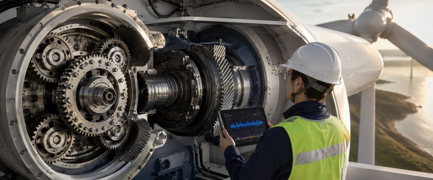
Bearings, not gear teeth, drive most gearbox failures in wind turbines. Recent industry statistics show bearing surface failures account for 76% of all gearbox failures, with gear issues now a secondary concern, according to the U.S. Department of Energy's Clean Energy Manufacturing Initiative statistics on bearing-driven gearbox failures.
That single shift in perspective changes how reliability engineers should inspect, monitor, and maintain every gearbox in wind turbine service. Teams that still center their strategy on visible gear wear often miss the earlier warning signs in bearings, especially in planetary and high-speed sections where damage can develop undetected and then accelerate fast.
For maintenance managers and plant operations leaders, the practical question isn't whether the gearbox matters. It's where to focus limited diagnostic effort, crane windows, oil sampling discipline, and condition monitoring budgets so failures are caught before they become long outages.
Table of Contents
- The High Cost of Wind Turbine Gearbox Downtime
- Understanding the Gearbox Role and Design
- Dominant Failure Modes and Their Root Causes
- Advanced Condition Monitoring and Data Interpretation
- Proactive Maintenance and Reliability Strategies
- Case Example Detecting a Planetary Stage Bearing Fault
- Implementing Your Predictive Maintenance Program
The High Cost of Wind Turbine Gearbox Downtime
A gearbox failure is rarely just a component problem. It becomes a production loss, a crane planning problem, a spare-parts problem, and usually a budget problem at the same time.
Industry data shows that gearboxes account for 18% of total wind turbine capital costs and can cause up to 60 days of downtime per single fault, with an average failure resulting in 18.38 days of lost operation time, making them the most costly rotating component for reliability engineers to manage, according to this wind turbine gearbox downtime analysis. For operations leaders, that means even one missed defect can erase the value of a lot of routine PM work.
A common mistake is treating the gearbox in wind turbine service like a conventional industrial reducer with similar inspection priorities. It isn't. The loading is highly variable, access is difficult, and the cost of being wrong is amplified by weather windows, mobilization logistics, and lost generation.
Why the usual maintenance focus misses the real issue
Too many programs still bias inspections toward gear tooth damage because gear wear is easier to visualize and easier to explain. But that mindset often delays the right action on bearing distress, which usually gives the earlier and more actionable warning signs.
Practical rule: If the maintenance strategy is built mainly around gear wear inspection, the program is usually reacting too late.
The better business case is to shift effort toward early bearing diagnostics, tighter oil cleanliness control, and fault confirmation before the defect migrates into adjacent components. Teams trying to lower total lifecycle cost usually get more value from that approach than from broad, calendar-based gearbox interventions. That same logic sits behind stronger maintenance cost reduction strategies in other critical rotating assets as well.
Understanding the Gearbox Role and Design
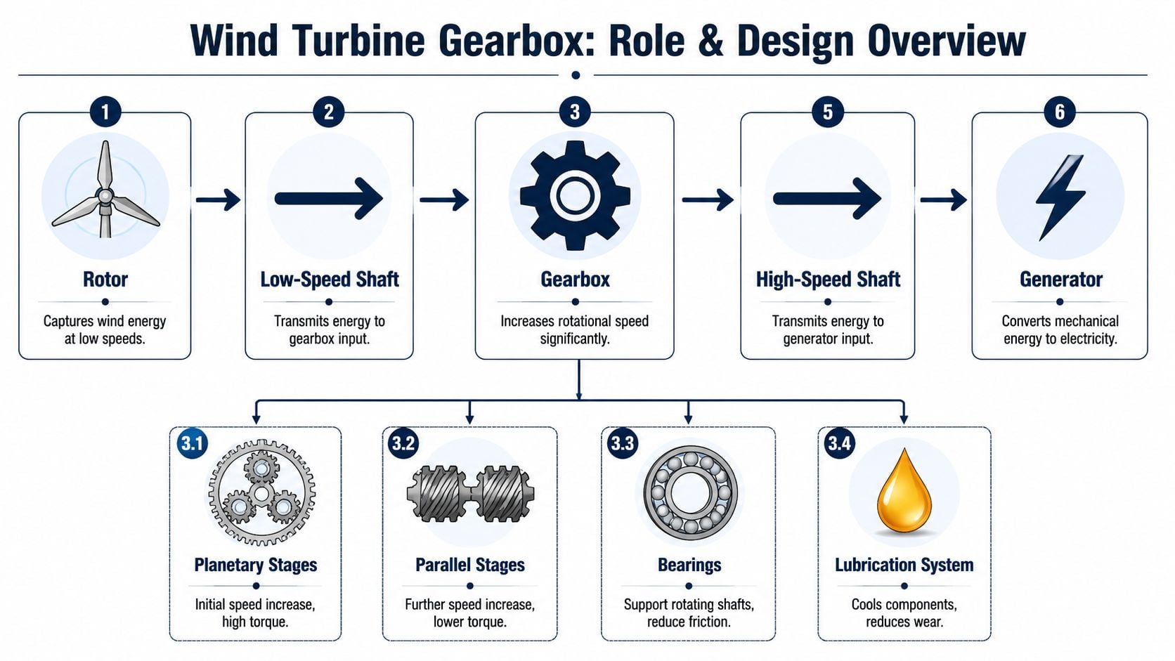
The gearbox exists because rotor speed and generator speed don't naturally match. Wind turbine blades turn relatively slowly and generate high torque. The generator needs much higher rotational speed to produce electricity efficiently. The gearbox bridges that mismatch.
A simple way to explain it is to compare it to a vehicle transmission. The machine trades one operating condition for another. In a wind turbine, it converts low-speed, high-torque input into high-speed, lower-torque output that the generator can use.
Why the gearbox exists
The gearbox in wind turbine operation has to manage more than speed increase. It also has to distribute load through multiple stages while surviving variable wind, start-stop events, grid-related transients, and the internal heat generated by meshing gears and loaded bearings.
That's why reliability work on these assets can't stop at basic gear checks. Engineers need to think about torque path, shaft support, bearing loading, lubrication flow, and where weak signals can hide.
This visual helps frame the functional path through the drivetrain.
What sits inside a typical gearbox
Most utility-scale gearboxes use a multi-stage arrangement. The exact layout varies by turbine platform, but the logic is consistent.
- Planetary stage: This first stage handles the highest torque. In a planetary arrangement, multiple planet gears share load around a central sun gear. That compact geometry is efficient, but diagnostics can be difficult because the stage runs at low speed and the signals are often weak.
- Parallel stages: These follow the planetary section and continue the speed increase. They often produce stronger vibration energy, which is useful for monitoring but can also mask defects elsewhere.
- Bearings: Bearings support shafts and gears while controlling radial and axial loads. Axial load is force acting along the shaft centerline. Radial load acts perpendicular to it. Both matter in helical and planetary arrangements.
- Lubrication system: Oil doesn't just lubricate. It removes heat, separates contact surfaces, carries wear debris to filters, and provides one of the best windows into internal distress.
A common field example is the multi-stage gearbox used in a 1.5 MW class wind turbine, where the first stage takes the brunt of torque multiplication and the later stages increase shaft speed toward generator requirements. From a reliability standpoint, this matters because the highest-load zone and the easiest-to-monitor zone often aren't the same place.
The teams that understand internal load path usually make better inspection decisions than teams that rely only on alarm thresholds.
For engineers who manage mixed fleets of reducers, speed increasers, and turbine drivetrains, this is why wind assets shouldn't be grouped with standard plant gear units in a single monitoring template. The failure physics are different, and so are the inspection priorities for industrial gearbox reliability programs.
Dominant Failure Modes and Their Root Causes
The industry has spent years talking about gears as if they were the main reliability problem. They aren't. The more useful diagnostic starting point is bearing distress.
According to the National Renewable Energy Laboratory's Gearbox Reliability Database, 76 percent of wind turbine gearbox failures are caused by bearing issues, while only 17 percent result from gear failures, and bearing damage often appears prematurely within 5% to 20% of designed service life, as described in this review of bearing and gearbox failures in wind turbines. That gap between expected life and real field behavior is why standard life calculations often fail to predict actual intervention timing.
Bearing failures lead the problem set
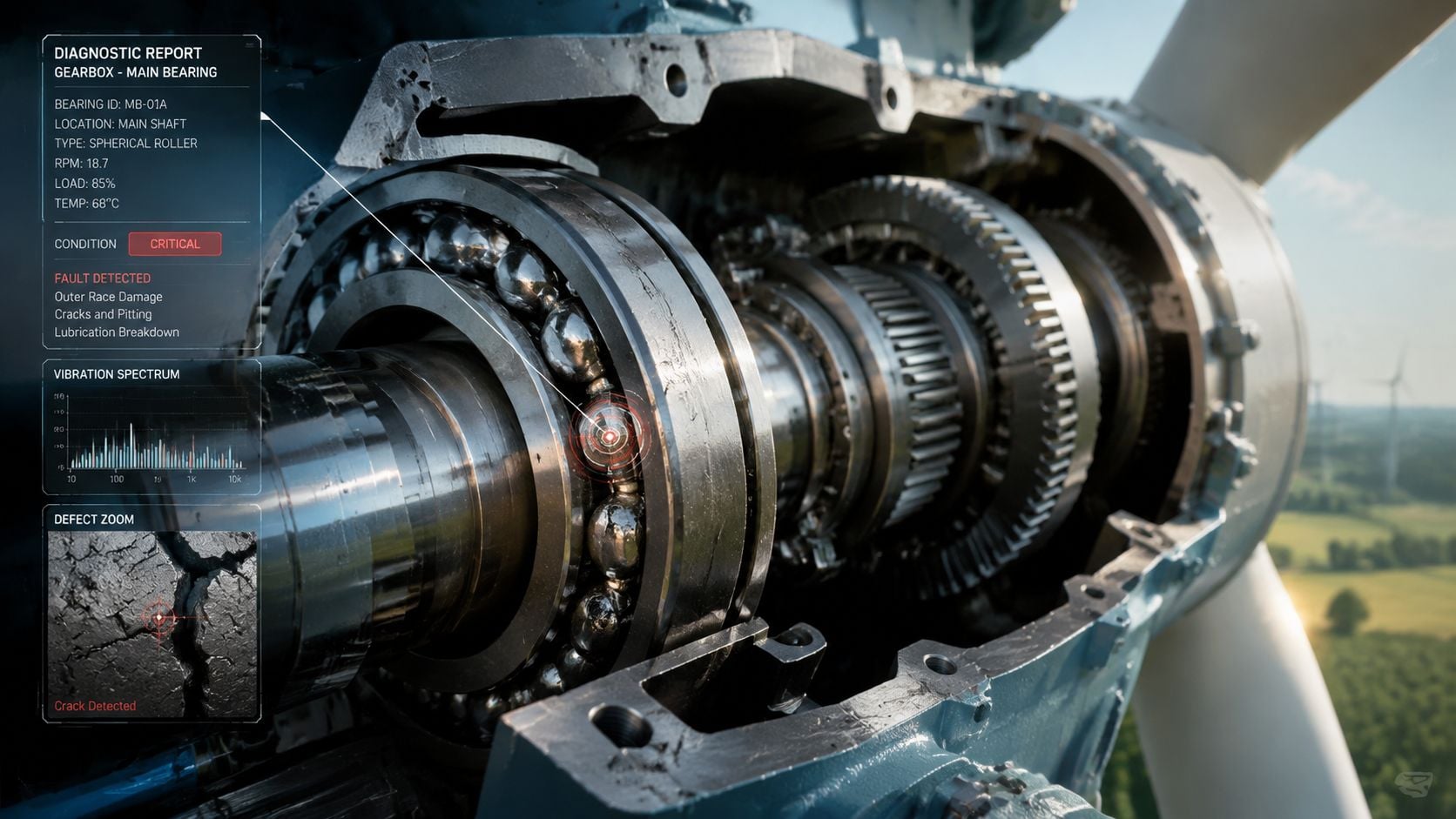
The most important bearing failure modes aren't interchangeable. Each one leaves different clues.
- Axial cracking: This is crack formation associated with axial stress and sliding conditions in bearing rollers. It has been identified as the prevalent failure mode in the field, especially in intermediate and high-speed bearing locations.
- Scuffing: This is surface damage caused when lubricant film breaks down and opposing surfaces contact under load. Once scuffing starts, heat and metal transfer can accelerate damage quickly.
- Surface distress and debris-related wear: Fine particles in the oil can act as abrasives and can also serve as evidence that a defect has already started.
- Micropitting: This is a fine-scale surface fatigue process often associated with marginal lubrication film strength. Engineers may first associate it with gears, but the underlying lubrication weakness often affects the whole contact system.
A practical example is a large onshore turbine where a small high-speed bearing defect first appears as a modest increase in vibration around a bearing frequency band. If that signal is dismissed as noise, the defect can progress into heat generation, debris release, oil contamination, and secondary gear distress. By the time visible gear damage shows up, the bearing was already the initiating event.
Why these failures start earlier than teams expect
Bearing life in wind service is strongly affected by conditions the gearbox doesn't see on a test stand. Variable loading, transient torque reversals, lubrication starvation during cold starts, contamination ingress, and misalignment all change real contact behavior.
The practical root causes usually cluster into a few categories:
- Lubrication film weakness: If oil can't maintain a separating film, metal surfaces touch under load.
- Contamination: Water, dirt, and wear particles increase abrasive contact and disrupt film formation.
- Sliding in stressed zones: Bearings aren't failing only from classic rolling contact fatigue. Sliding and mixed lubrication regimes matter.
- Load transients: Gusts, starts, stops, and drivetrain events can create stress patterns that standard steady-state assumptions miss.
A bearing defect that looks minor in the data can still be high risk if it sits in a location that sheds debris into the rest of the gearbox.
That's the reason root cause analysis has to connect signal, location, lubrication condition, and operating context. Looking at one data stream in isolation usually leads to late calls or wrong calls.
Advanced Condition Monitoring and Data Interpretation
A predictive program only works if the monitoring method matches the failure mode. General alarms don't do that well. Bearing-focused diagnostics do.
One persistent blind spot is the planetary stage. Existing guidance often says “use predictive maintenance” without addressing the signal-processing challenge inside low-speed planetary sections. Research on this problem notes that early-stage faults in the planetary gear stage are hard to detect because their frequencies are masked by higher-energy meshing vibrations from parallel stages, and Empirical Wavelet Transform enables adaptive detection of these weak signals, as discussed in this planetary stage fault detection study.
What vibration data should reveal
Vibration analysis remains the fastest route to confirming many gearbox faults, but only if the analyst is targeting the right features.
For bearing diagnostics, engineers often calculate characteristic frequencies such as:
- BPFO: Ball Pass Frequency Outer race. A frequency associated with rolling elements passing a defect on the outer race.
- BPFI: Ball Pass Frequency Inner race. A frequency associated with a defect on the inner race.
- BSF: Ball Spin Frequency. A frequency tied to defects on the rolling element itself.
- FTF: Fundamental Train Frequency. A lower-frequency feature related to cage rotation.
In a wind turbine gearbox, these frequencies usually don't appear as perfectly clean lines. Load variation smears them. Modulation creates sidebands. Structural resonance can amplify one region and bury another.
A useful workflow for a suspected inner race issue in a fleet turbine is:
- Review the trend first. Rising overall vibration alone isn't enough.
- Check enveloped or demodulated spectra for bearing-related activity.
- Compare axial, radial, and high-frequency channels.
- Correlate the signal with operating state and oil findings.
- Decide whether the fault is stable, accelerating, or already producing debris.
Oil analysis that actually helps decision making
Oil analysis is often underused because teams reduce it to viscosity and a pass-fail contamination flag. That misses the gearbox story.
The most useful gearbox oil work includes:
- Particle counting: Tracks solid contamination and can indicate active wear.
- Wear debris review: Particle shape and appearance help distinguish rubbing wear from fatigue-related distress.
- Elemental analysis: Looks for metal signatures that suggest which internal components are shedding material.
- Moisture review: Water changes lubrication performance and corrosion risk.
- Filter and drain inspection: Direct debris inspection often clarifies whether a vibration anomaly is urgent.
Field advice: If oil debris and bearing-frequency vibration rise together, the team should stop debating whether the fault is real and start planning the intervention.
Acoustic methods and borescope inspection can also add value, especially when vibration is ambiguous or when confirmation is needed before scheduling a crane event. But they work best as confirmatory tools, not as substitutes for disciplined trending.
Condition Monitoring Techniques for Gearbox Faults
| Technique | Primary Application | Best For Detecting | Limitation |
|---|---|---|---|
| Vibration analysis | Continuous or periodic mechanical condition monitoring | Bearing defect frequencies, gear mesh changes, looseness, misalignment patterns | Signal masking is common in complex multi-stage gearboxes |
| Oil analysis | Lubricant and wear condition assessment | Debris generation, contamination, lubrication breakdown, active wear | It may show that damage exists without pinpointing exact location |
| Acoustic emission | High-frequency stress wave detection | Very early surface distress and crack-related activity | Data interpretation can be difficult in noisy operating environments |
| Temperature trending | Thermal condition surveillance | Lubrication loss, abnormal friction, cooling issues | Temperature usually rises after damage has progressed |
| Borescope inspection | Internal visual confirmation | Surface scuffing, pitting, visible cracks, debris accumulation | Requires access planning and may not catch the earliest hidden defects |
Teams building more mature monitoring workflows often combine these methods with automated analytics and escalation logic rather than relying on a single alarm source. That's especially useful when scaling a fleet-wide program with machine-learning-supported predictive maintenance.
Proactive Maintenance and Reliability Strategies
Condition monitoring only pays off when it drives a different maintenance decision. In wind service, the better strategy is usually not “inspect everything more often.” It's “rank failure modes correctly, then act earlier on the ones that create the biggest operational consequence.”
Industry benchmarks report an annual gearbox failure rate of 1 in 145 operational turbines, with failure density driven largely by lubrication-related issues that are mitigated through oil quality control and vibration-based monitoring, according to this overview of gearbox failure benchmarks and lubrication control. That points to a practical conclusion. Lubrication discipline isn't a housekeeping task. It is a primary reliability control.
Building the maintenance plan around failure consequence
A useful framework combines FMEA and RCM.
FMEA, or Failure Modes and Effects Analysis, asks what can fail, how it fails, and what happens next. RCM, or Reliability-Centered Maintenance, asks what maintenance task is technically appropriate for that failure mode and consequence.
For a modern turbine gearbox, that often leads to a plan like this:
- Planetary bearing risk gets priority: These locations are difficult to monitor and expensive to ignore, so they deserve tighter review of low-speed vibration signatures and oil debris trends.
- High-speed stage alarms get faster escalation: These bearings can move from warning to damaging debris generation quickly.
- Lubrication tasks become precision tasks: Oil changes, filter changes, breather condition, contamination control, and sample point discipline should be standardized, not left to technician preference.
- Time-based replacement gets challenged: If the condition data is stable and clean, fixed-interval intervention may create unnecessary crane work and handling risk.
This process view is easier to sustain with a visual operating model.
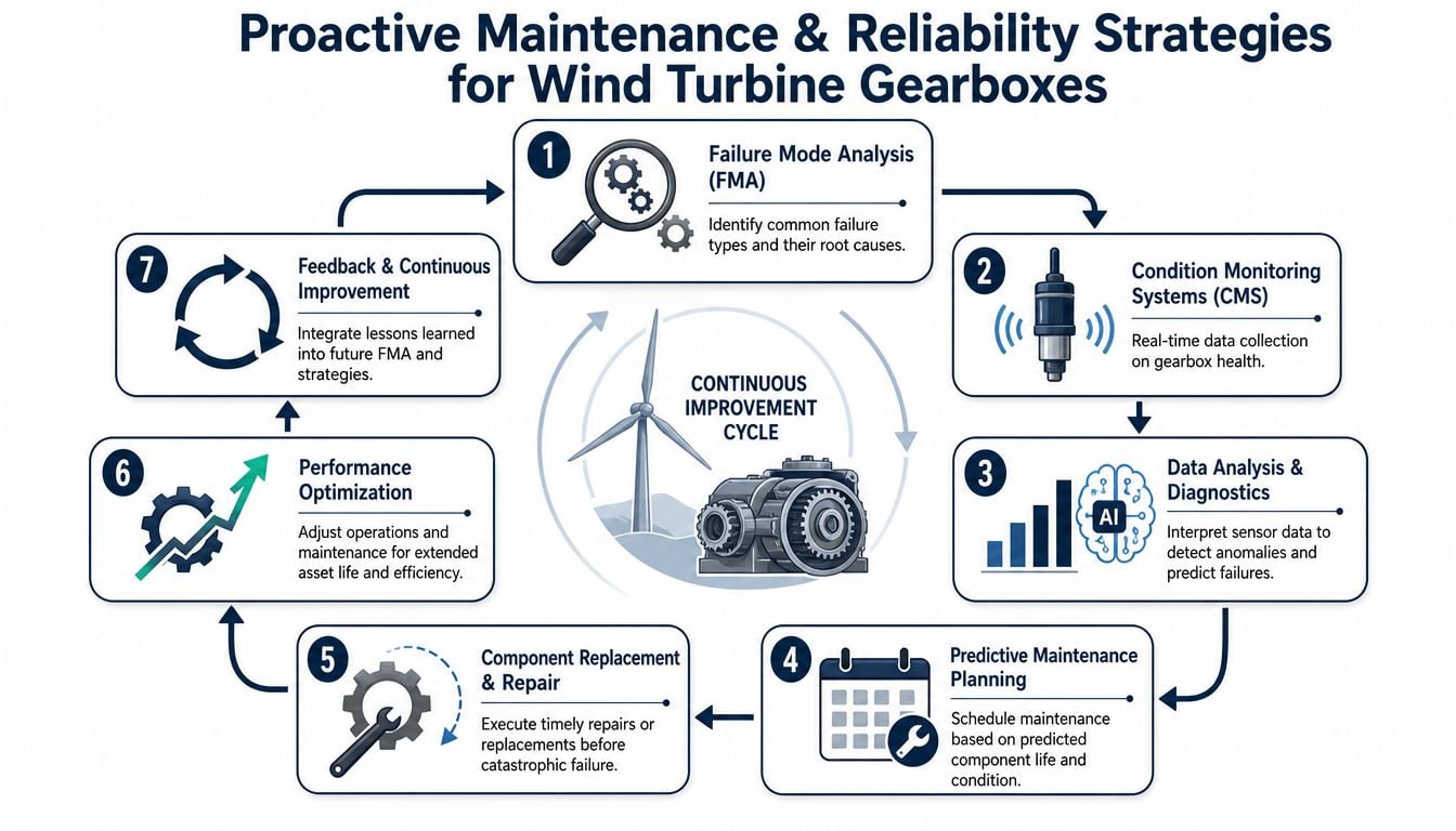
A practical example would be an RCM-based plan for a Nordex N149 gearbox. The engineering team would separate high-consequence hidden failures from visible degradations, then assign condition-based tasks to the bearing-dominant risks and visual inspections to secondary concerns. The key isn't the template. It's that the tasks match actual failure physics.
Spare parts and repair readiness
Planned repair quality depends on readiness long before the fault alarm appears.
A few decisions matter:
- Critical spares: Stocking filters, seals, sampling hardware, and selected bearing-related components can shorten decision lag.
- Repair pathway: Teams should define in advance when they'll repair in situ, exchange a component, or replace the gearbox.
- Manufacturing support: For lower-volume or long-lead support items, engineers evaluating optimizing production with additive manufacturing can sometimes reduce exposure on replacement-part availability.
- Maintenance philosophy: The wrong mix of preventive and predictive tasks wastes labor on low-risk work and still misses actual defects. A more durable approach is to align the program around predictive vs preventive maintenance decisions.
The strongest turbine gearbox programs don't just detect faults earlier. They make the organization ready to act when the fault appears.
Case Example Detecting a Planetary Stage Bearing Fault
A wind farm operator had one turbine with a gearbox that looked healthy on standard supervisory data. Power production was still acceptable. Temperature was stable. No obvious warning justified a shutdown.
The issue first surfaced in continuous vibration data. A low-amplitude pattern appeared in a band associated with a planetary bearing defect, but the signature was weak and partially buried by stronger vibration from later stages. That's typical for low-speed planetary faults. The data by itself suggested caution, not immediate action.
Initial alert and diagnostic escalation
The reliability team didn't treat the first alert as proof. They treated it as a trigger for better evidence.
They reviewed trended spectra, looked for repeatability across operating conditions, and cross-checked recent oil sample history. The oil results showed a subtle increase in fine metallic debris. A follow-up sample and filter inspection supported the same conclusion. The fault wasn't severe yet, but it was active.
At that point, the team used a structured decision path:
- Signal persistence: Was the feature repeatable across multiple runs?
- Corroborating evidence: Did oil debris support active internal distress?
- Location risk: Was the suspected fault in a section that could contaminate adjacent components?
- Access window: Could the repair be aligned with weather, labor, and crane planning?
A technician also reviewed reference patterns from prior bearing events using this bearing fault detection resource for vibration analysis. The purpose wasn't to force a match. It was to avoid dismissing a developing pattern solely because the amplitude was still modest.
The maintenance decision
Management had two choices. Defer and continue monitoring, or schedule a controlled intervention during an available maintenance window.
They chose the planned repair. That decision mattered because planetary-stage defects rarely stay isolated once debris starts moving through the oil circuit. A scheduled outage gave the team control over labor, lift equipment, replacement scope, and restart preparation. An unplanned event would likely have turned a localized bearing problem into a much larger gearbox repair.
The result was straightforward. The fault was confirmed during maintenance. The bearing showed early-stage distress before secondary damage spread. The turbine returned to service after a controlled outage rather than a forced long-duration failure event.
This is the operational value of predictive work on a gearbox in wind turbine service. The biggest win often isn't proving the model was clever. It's avoiding emergency logistics, collateral damage, and avoidable downtime.
Implementing Your Predictive Maintenance Program
The strategic shift is simple. Stop organizing gearbox maintenance around the assumption that gears are the primary threat. Build the program around bearing health, lubrication control, and fault confirmation in the stages where defects hide early.
For most fleets, a practical rollout starts with three steps.
First, perform a criticality review across the turbine population. The goal is to identify which gearboxes carry the greatest production consequence, weakest monitoring coverage, or highest history of repeat interventions.
Second, establish a baseline condition assessment. That means more than checking existing alarms. It means collecting and reviewing vibration, oil, temperature, and maintenance history in a way that defines current risk by component zone.
Third, launch a pilot predictive program on a small group of high-consequence turbines. Use it to refine alarm logic, reporting cadence, decision thresholds, and repair planning workflow before scaling across the fleet.
A gearbox in wind turbine service doesn't fail on a spreadsheet. It fails in the field, under variable load, with expensive access constraints and real production consequences. The best programs respect that reality. They target the dominant failure mode, use multiple confirming data streams, and turn diagnostics into scheduled action before the machine forces the decision.
A free reliability assessment can help identify which turbine gearboxes need immediate diagnostic attention, where bearing-focused monitoring is missing, and how to prioritize predictive maintenance investments across the fleet. Forge Reliability provides no-cost reliability assessments for teams looking to reduce unplanned downtime, improve condition monitoring coverage, and build a practical gearbox strategy grounded in real operating risk.