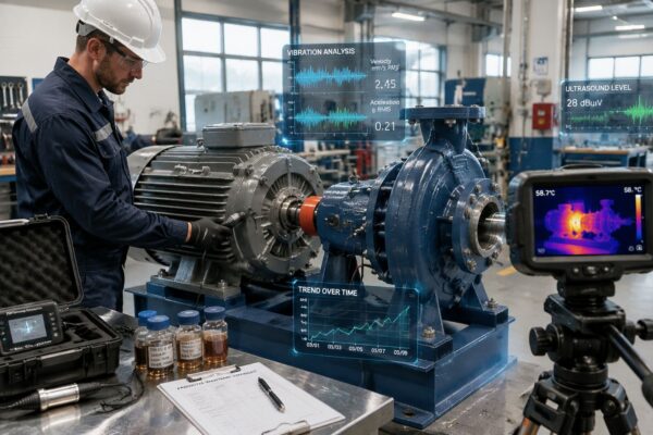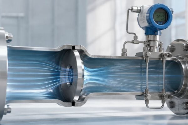
A maintenance technician finds a stainless float sitting low in a chemical dosing skid. The level signal has drifted, the pump keeps cycling, and the first assumption is an instrument problem. On inspection, the steel hollow ball has collapsed at its weld seam. The failure has allowed process fluid onto the mezzanine and turned a small component into a containment event.
That pattern is common in principle, even when the equipment differs. Supplier catalogs make hollow balls look simple by emphasizing diameter, material, and finish. Reliability teams need a different view, one based on wall stability, weld integrity, corrosion pathways, loading, and inspection evidence. A steel hollow ball can be a float, a valve element, a rolling component, or an impact absorber. In each case, the shell is part of the machine's load path.
Table of Contents
- Why a Steel Hollow Ball Deserves Engineering Respect
- How Steel Hollow Balls Are Actually Manufactured
- Material and Mechanical Properties That Drive Performance
- Industrial Applications and What Each One Demands
- Common Failure Modes in Plant Service
- Inspection and NDT Methods That Actually Work
- Selecting and Specifying the Right Hollow Ball
- Putting It All Together and Next Steps
Why a Steel Hollow Ball Deserves Engineering Respect
The shell carries the risk
A spherical shell distributes external load efficiently, but that efficiency doesn't make it immune to local defects. Thin material, a poor weld profile, or a small dent can change the stress pattern substantially. The equator weld, pole regions, stem penetrations, and attachment points deserve more attention than the catalog photograph usually suggests.
A hollow sphere also behaves differently from a solid ball during collapse. Wall thickness is the dominant geometric variable, and even modest variation can alter stiffness and pressure resistance. A shell that meets its nominal outside diameter may still fail prematurely if the wall is locally thin or the weld has incomplete penetration.
Practical rule: Treat the weld and shell thickness as functional dimensions, not manufacturing details.
The 304 stainless float in the dosing skid illustrates the purchasing failure behind many field failures. The component may have matched the specified diameter and alloy, yet the purchase file contained no meaningful evidence of weld procedure qualification, weld inspection, or pressure testing. A material certificate alone couldn't establish that the finished sphere would remain hermetic in service.
Catalog data rarely answers the reliability questions
A reliability review should ask for evidence that connects design intent to manufacturing control:
- Weld documentation: The supplier should identify the weld procedure, filler or joining method where applicable, and inspection acceptance criteria.
- Geometry records: The receiving team should verify outside diameter, wall thickness, concentricity, and obvious distortion.
- Integrity testing: A sealed float or pressure-exposed component needs a documented hydrostatic or suitable pneumatic test, with the test conditions defined.
- Service compatibility: The specification should identify process media, temperature, pressure, cycling, and exposure to contamination.
The historic Bathysphere shows how seriously hollow steel spheres can be engineered. The 4.5-foot-diameter sphere had 1-inch-thick walls and carried two occupants to 800 feet off Bermuda on 6 June 1930, reaching a depth roughly three times deeper than any human had reached before at that time, as described in this historical account of the Bathysphere. That vessel was designed for extreme external pressure, not catalog convenience.
The lesson for a chemical skid is more practical. A steel hollow ball doesn't need to be large or dramatic to deserve pressure-vessel thinking. If its failure can release fluid, interrupt control, damage a bearing, or upset a safety function, the part belongs in the equipment reliability review.
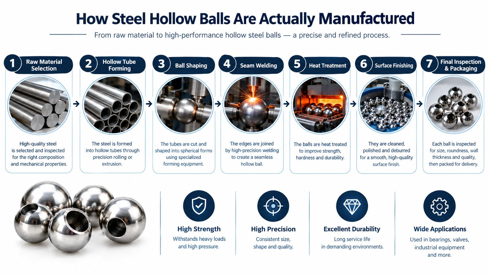
How Steel Hollow Balls Are Actually Manufactured
Manufacturing route determines where defects are likely to appear. Receiving inspection works best when the inspector recognizes the construction method instead of applying the same checklist to every sphere.
Three forming routes create different inspection priorities
Stamped hemispheres start as sheet material drawn into two cup-like halves. The halves are joined around the equator, so the circumferential weld becomes the dominant quality variable. Undercut, porosity, lack of fusion, and incomplete penetration can remain hidden beneath a smooth-looking finish.
Deep-drawn cup construction can produce a clean surface and relatively thin shell, but the process demands accurate alignment before welding. A displaced joint can create a local ridge, eccentricity, or uneven load path. A valve manufacturer may accept the visual finish while a maintenance engineer should question whether the finished ball is concentric enough for the seat and stem arrangement.
Segmented welded plate construction suits larger spheres. Rolled segments create multiple seam orientations and therefore more weld length, more intersections, and more locations requiring examination. Each seam should have traceability to the weld procedure and inspection record.
The 2022 Fraunhofer IFAM and Hollomet process demonstrates another engineered route. It begins with polystyrene cores, deposits a metal powder-binder suspension in a fluidized-bed environment, and produces hollow steel balls for ball valves and bearings that are 40% to 70% lighter than solid balls, according to the documented hollow-ball process description. The process matters because it shows that hollow geometry can be deliberately manufactured for rotating equipment, not merely fabricated as a decorative shell.
Receiving inspection should follow the process
A receiving inspector should first identify the seam layout and forming route. Visual examination then looks for irregular bead width, crater cracks, undercut, spatter, grinding scars, and deformation. Surface appearance isn't proof of internal soundness, so weld examination and integrity testing must match the component's criticality.
The shipment package should include:
- Material traceability: Mill certificate and heat or batch identification.
- Welding controls: Weld procedure specification and evidence that the procedure is qualified for the service.
- Test records: Hydrostatic or hermeticity test report where the component is sealed or pressure exposed.
- Dimensional records: Measured diameter, wall thickness, and relevant alignment tolerances.
Teams building a formal manufacturing risk review can use an FMEA for manufacturing to connect each process step to a potential field failure. The useful output isn't a generic score. It identifies which defect can escape, which inspection catches it, and who owns the response.
Material and Mechanical Properties That Drive Performance
A steel hollow ball specification should name more than an alloy and outside diameter. The engineer needs to control material grade, wall thickness, sphericity, and surface condition, because each variable affects a different failure mechanism.
Wall thickness governs stiffness
Supplier data places common hollow-ball outside diameters at approximately 15 mm to 1000 mm, with wall thicknesses from 0.4 mm to 5 mm, as shown in this stainless hollow-ball dimensional reference. Small precision grades may use 0.8, 1.0, 1.5, 2.0, or 3.0 mm walls for 201 stainless. Those figures aren't interchangeable design recommendations. They show why a nominal diameter without a controlled wall specification leaves a major reliability question unanswered.
Reducing thickness lowers mass and rotational inertia, but it also reduces shell stiffness, load capacity, and dent resistance. A 1 mm wall on a 100 mm ball doesn't have the same collapse behavior as a 2 mm wall on the same diameter, even though the outside dimensions match. Pressure, impact, bearing load, and cycle frequency must therefore be evaluated together.
Material selection adds another layer:
| Material Grade | Yield Strength (MPa) | Corrosion Resistance | Weldability | Typical Application |
|---|---|---|---|---|
| 304 stainless steel | Supplier-specific | Good in many general environments | Good, with heat-affected-zone control required | Floats and general process service |
| 316 stainless steel | Supplier-specific | Better resistance in chloride-bearing service | Good, with procedure control required | Chemical and wet environments |
| 316L stainless steel | Supplier-specific | Better resistance in chloride-bearing service | Strong choice for welded assemblies | Welded floats and sealed process components |
| Carbon steel | Supplier-specific | Requires protective coating or controlled environment | Generally practical with qualified procedures | Non-corrosive floats and dampers |
No yield-strength value should be accepted from a generic catalog unless it belongs to the exact grade, product form, heat treatment, and material certificate. Austenitic stainless grades can also lose toughness at cryogenic temperatures, so ambient-temperature assumptions don't automatically transfer to low-temperature service.
Geometry affects function
Sphericity means how closely the component approaches a true sphere. Poor sphericity can cause uneven valve-seat contact, unstable float movement, or concentrated rolling contact. Surface roughness isn't decorative either. A rough valve ball can accelerate seat wear, while a damaged float surface can collect deposits and alter movement.
Rolling applications require an even higher standard. ISO 3290-1:2014 specifies requirements for finished steel balls used in rolling bearings, while ANSI and ABMA ball-grade references address diameter variation, spherical form, and surface roughness, as summarized in this rolling-element standards reference. A general hollow sphere shouldn't be substituted for a precision rolling element because both parts are spherical.
For load-path decisions, the distinction between radial and axial load helps clarify whether the shell, raceway, stem, or seat is carrying the dominant force.
Industrial Applications and What Each One Demands
The same steel hollow ball can be reliable in one service and unsuitable in another. The right selection begins with the primary failure driver, not the application label.
Floats prioritize hermetic integrity
A level-control float depends on displacement and retained internal volume. The weld must remain sealed, the shell must resist process pressure and impact, and the material must tolerate the liquid. Pitting at the seam can eventually become a leak path, while internal contamination or fluid ingress can change buoyancy and make the level signal unreliable.
In a chemical dosing skid, the maintenance team should inspect for seam discoloration, localized pitting, denting, and evidence that the float is rubbing the guide or vessel wall. A float that moves slowly or sits lower than expected may have a leak long before the failure becomes visible.
Valve balls prioritize contact geometry
A hollow valve ball sees a different duty. Quarter-turn operation creates repeated seat contact, and trunnion-mounted designs transfer load through the stem and support arrangement. Cavitation can damage the surface when local pressure conditions cause vapor bubbles to form and collapse. Concentricity, surface finish, and stem-interface integrity matter more than low mass alone.
The maintenance symptom is often rising actuator torque, leakage past the seat, or irregular travel. A ball that appears intact can still have a damaged sealing surface or a distorted bore.
Rolling elements prioritize fatigue control
A hollow rolling element must retain spherical form under repeated contact stress. NASA testing examined 12.7 mm SAE 52100 hollow balls formed as hemispherical shells with a nominal 2.54 mm wall thickness, demonstrating that hollow geometry can be evaluated for high-load bearing-related use when material quality and forming are controlled, as documented in the NASA rolling-element fatigue report.
The relevant maintenance clues are flaking, spalling, vibration, rising bearing temperature, and lubricant debris. A general-purpose hollow ball isn't automatically a bearing-grade rolling element. It needs controlled fatigue performance, heat treatment, surface finish, and dimensional accuracy.
Dampers and snubbers absorb punishment
Dampers and hydraulic snubbers impose impact, reversal, and cyclic loading. Here, ductility and weld integrity become decisive. A thin shell may save mass but dent under a transient load, while a brittle or poorly fused seam can crack after repeated shocks.
Operations teams comparing these use cases often need better traceability than a spreadsheet can provide. A structured workflow for replacing Excel in manufacturing can help connect asset criticality, inspection records, supplier documents, and failure history without treating each purchase as an isolated transaction.
Common Failure Modes in Plant Service
Root cause analysis should start with the field symptom, then work toward the mechanism. A deformed steel hollow ball, for example, is an observation. Collapse from overpressure, impact damage, unsupported handling, or cyclic fatigue is the mechanism that must be proven.
Corrosion and cracking leave different clues
Corrosion pathways often begin where the design creates a wet pocket. Pitting can attack a weld seam, crevice corrosion can develop where a stem penetrates the shell, and galvanic attack can occur when carbon steel contacts stainless trim in the presence of an electrolyte. Technicians may see staining, pinholes, loss of buoyancy, or a gradual change in valve torque.
Cracking typically follows a stress raiser. Weld toes, sharp transitions, grinding marks, and attachment points can initiate fatigue cracks under repeated movement. Hydrogen embrittlement is a separate concern in sour service, where absorbed hydrogen can reduce ductility and promote cracking. A crack that opens during thermal cycling may be invisible during a cold visual inspection.
RCA discipline: Record the crack origin, direction, loading history, and local geometry before assigning blame to the material.
Deformation can be permanent or progressive
Denting usually points to impact, poor handling, or contact with a guide. Permanent collapse on a float points toward pressure exceeding shell stability, local wall thinning, or a manufacturing defect. Brinelling, which is a permanent indentation caused when a ball seats under load without adequate rotation, is especially relevant to rolling contacts and can produce vibration before obvious spalling appears.
Weld defects can escape a supplier's visual inspection. Porosity, lack of fusion, undercut, and incomplete penetration may only become active after pressure cycling, vibration, or temperature changes. The technician may find a slow leak, a change in float response, or a crack that follows the weld rather than the parent metal.
Rolling fatigue requires load history
Rolling-contact fatigue develops through repeated subsurface and surface stress. Engineers use S-N curves, which relate stress amplitude to cycles to failure, and mean-stress corrections when the operating load includes a sustained component. Those tools are only useful when the actual shell geometry, material condition, contact load, and duty cycle are known.
NASA research evaluated hollow balls for high-speed bearing service because lower ball mass reduces centrifugal-force-related problems and heat generation at very high DN values. One study examined cylindrically hollow drilled balls in bearings operating up to DN 2.1 million, tying the design to extreme-speed mechanical applications rather than general-purpose service, as shown in the NASA high-speed bearing study.
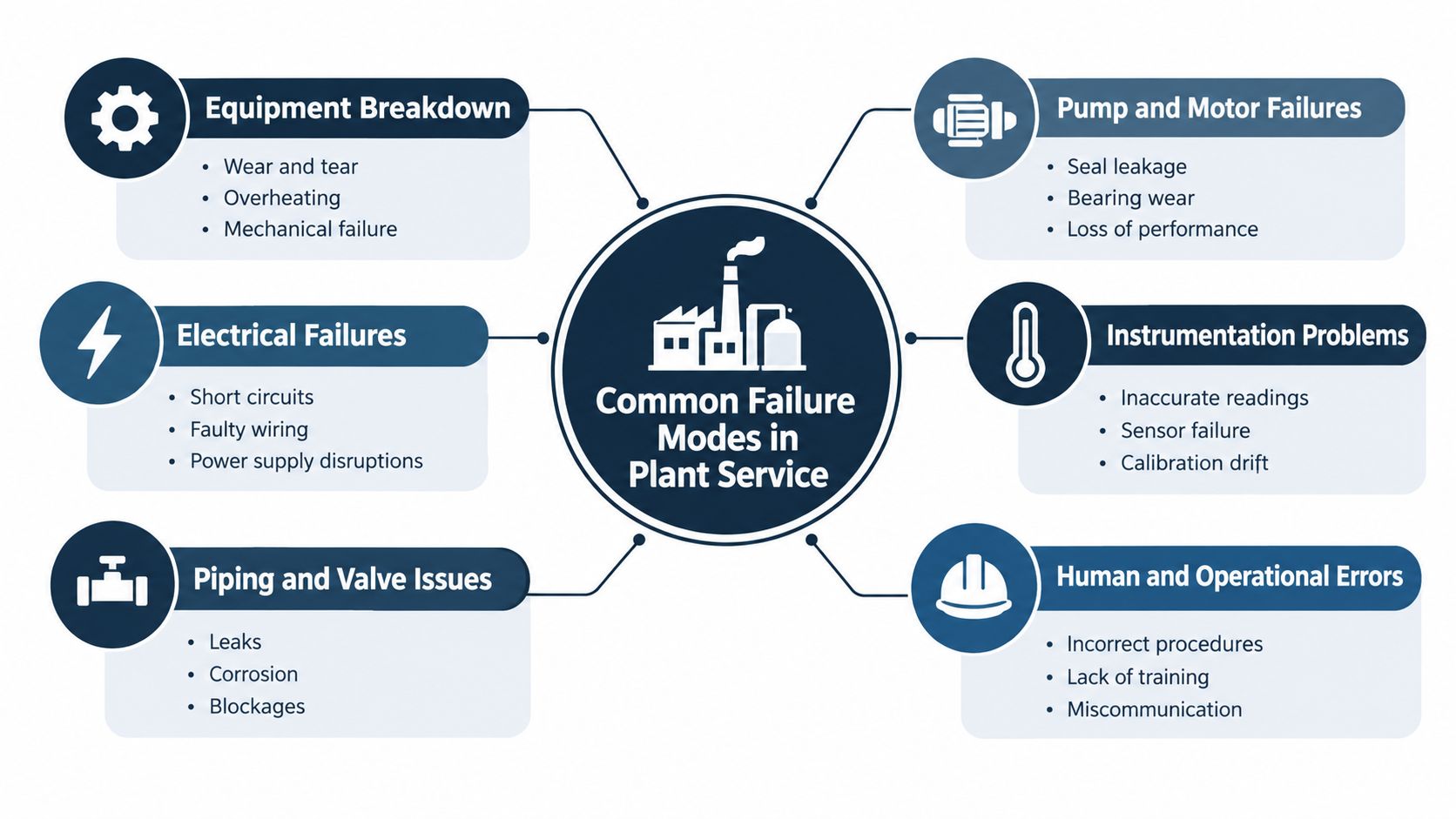
A bearing failure investigation should separate rolling-element damage from lubrication, alignment, preload, contamination, and raceway problems. The bearing failure resource can support that broader diagnostic view, but the failed sphere still needs direct examination.
Inspection and NDT Methods That Actually Work
Inspection should match the question being asked. No single non-destructive testing method proves every aspect of a hollow ball's integrity.
| Lifecycle Stage | Recommended Methods | Defects Detected |
|---|---|---|
| Receiving inspection | Dimensional checks, visual weld inspection, dye penetrant or magnetic particle testing, pressure or hermeticity testing | Distortion, surface-breaking cracks, some weld discontinuities, leaks |
| In-service monitoring | Ultrasonic thickness gauging, eddy current testing where suitable, acoustic emission under load, functional checks | Wall loss, surface cracking, active crack growth, loss of buoyancy or abnormal movement |
| Post-failure investigation | Metallographic sectioning, scanning electron microscopy, chemical analysis | Weld structure, fracture origin, fatigue features, material identity and contamination |
At receipt, dimensional verification should confirm diameter, roundness, wall thickness at representative locations, and alignment of any stem or bore. Hydrostatic testing is generally preferred where the component and service permit it. Pneumatic testing can expose hermeticity problems, but stored energy makes the risk assessment more demanding.
Dye penetrant testing reveals surface-breaking defects on suitable clean surfaces. Magnetic particle inspection can find surface and near-surface discontinuities in ferromagnetic material, but it isn't appropriate for every stainless grade. Visual inspection remains valuable for finish, distortion, and weld profile, yet it won't reveal subsurface porosity.
During operation, ultrasonic thickness gauging tracks wall loss, although internal curvature and access can skew readings. Eddy current testing can detect surface cracks on suitable conductive materials without direct coupling, while acoustic emission can identify active cracking as a loaded component produces transient stress waves.
The inspection team should choose equipment and probe technique deliberately. Guidance on ultrasound testing equipment is useful when building a practical program, but method qualification still belongs to the site and component.
Post-failure work should section through the seam, preserve the fracture surface, examine morphology with scanning electron microscopy where justified, and verify chemistry against the purchase specification. A low-cost visual screen suits noncritical decorative service. A containment-critical float or bearing element needs layered verification.
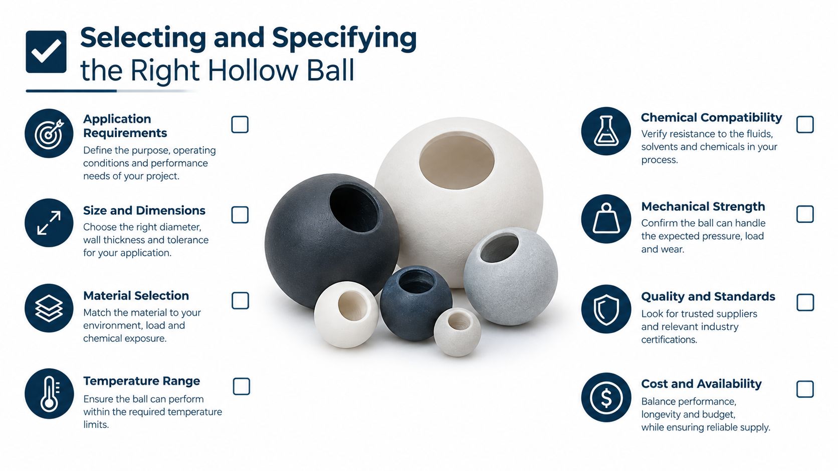
Selecting and Specifying the Right Hollow Ball
Procurement should begin with the load case, not the supplier's standard size. Wall thickness must be tied to operating pressure, buoyancy, impact, rotational load, and expected cycling. A catalog dimension is a starting point, not an engineering acceptance criterion.
The purchase specification should state:
- Material and condition: Identify the grade, product form, heat treatment, and corrosion environment. Use 304 or 316 stainless where appropriate, 316L for welded assemblies when its lower carbon content supports corrosion control, and carbon steel only where the environment and protection system justify it.
- Shell geometry: Define wall-thickness tolerance, sphericity, concentricity, and any bore or stem alignment requirement.
- Weld evidence: Require the weld procedure, inspection method, acceptance standard, and repair limits.
- Integrity testing: Require a documented leak, hydrostatic, or other suitable pressure test for sealed or pressure-exposed service.
- Surface condition: Specify roughness and finishing requirements where sealing, sliding, or rolling contact is involved.
A standard thin-wall design may suit a lightly loaded float in a controlled liquid. Heavy-wall or forged construction deserves review when the component sees pressure cycling, impact, frequent actuation, or high consequence of release. The upgrade should follow a documented criticality and life assessment, not a vague preference for “stronger” parts.
Before approval, engineering and maintenance should review shop drawings with Uptool so weld locations, inspection points, tolerances, and attachment details are visible before fabrication begins.
Putting It All Together and Next Steps
A reliable steel hollow ball program connects four decisions. The material must tolerate the process environment, wall thickness must suit pressure and dynamic loading, weld quality must be demonstrated rather than assumed, and inspection must reflect the component's criticality.
That discipline applies whether the ball sits inside a chemical float, a quarter-turn valve, a bearing, or a hydraulic snubber. These components deserve the same engineering control applied to valves, pumps, and pressure vessels because their failure can create leakage, loss of control, vibration, or an unplanned shutdown.
A practical reliability program records the specification, supplier evidence, installation condition, operating symptoms, and failure findings in one traceable system. Teams developing that structure can use a 12-month reliability program roadmap to connect component-level controls with broader asset strategy.
Forge Reliability offers predictive maintenance, condition monitoring, root cause failure analysis, and reliability consulting for plants that need stronger control over recurring failures. Request a free reliability assessment through Forge Reliability to pressure-test steel hollow ball specifications, inspection practices, and hidden failure exposure across float, valve, and bearing applications.